2012 Lexus LFA wheel
[x] Cancel search: wheelPage 12 of 128

10
■
■Driving position adjustment
1 Insert the key into the ignition switch
and then turn the key to the “ACC”
position.
2 Use the seat adjustment switches (A)
to move the driver seat. You should
be able to fully depress the brake
pedal with your knees slightly bent.
3 Adjust the height of the seat and the
position of the steering wheel. You
should be able to grip the top of the steering wheel with your elbows slightly bent
and your back at a comfortable angle.
4 If necessary, readjust the seat position.
5 Adjust the mirrors to ensure that you have a good view of the area behind the
vehicle.
■
■Starting the engine
1 With the brake pedal depressed, turn the key to the “ON” position.
2 Pull both paddle shift switches at the same time to select Neutral.
3 Press the “ENGINE START” switch to start the engine.
(A)
Page 22 of 128

20
Ideal driving position
An ideal driving position allows for smooth operational inputs and also helps to
reduce injuries in the event of a collision. Although the driving position employed by
racing drivers in competition offers maximum car control, it is not always practical for
use on public roads.
While the ideal driving position will vary depending on individual requirements and
driving conditions, please observe the following points in order to ensure a safe and
comfortable driving position:
■
■Seat slide adjustment
When sliding your seat back and forth, aim for a position that allows you to fully
depress the brake pedal with your knees slightly bent. Also, to ensure that you have
enough leverage to depress the brake pedal, make sure that your back rests firmly
against the seatback.
If your leg is fully extended to depress the brake pedal and a collision occurs, your
knee will not be able to help absorb any impact force. Instead, the full force of the
impact will be transferred to your lower back, possibly resulting in spinal injuries.
■
■Seat angle adjustment
When adjusting the seatback, aim for an angle that allows you to rest your back firmly
against the seatback with your hands gripping the top of the steering wheel and your
elbows slightly bent. Resting your back firmly against the seatback offers better body
support.
To maintain an adequate level of support, it is essential to make sure that your arms are
not over-reaching to touch the top of the steering wheel. Sitting too far away will force
you to lean forward when turning, compromising the support offered by the seatback.
Finally, make sure that the seatback is not reclined excessively, as this may result in
your body slipping under the seat belt in the event of a collision.
The seats in the LFA employ a racing bucket seat-inspired design and frames made
from CFRP (Carbon Fiber Reinforced Plastics) to ensure a highly rigid and supportive
construction.
To ensure that the seats are used to their maximum potential, always maintain an
appropriate driving position.
Page 25 of 128

23
Ideal driving position
■
■Steering wheel adjustment range
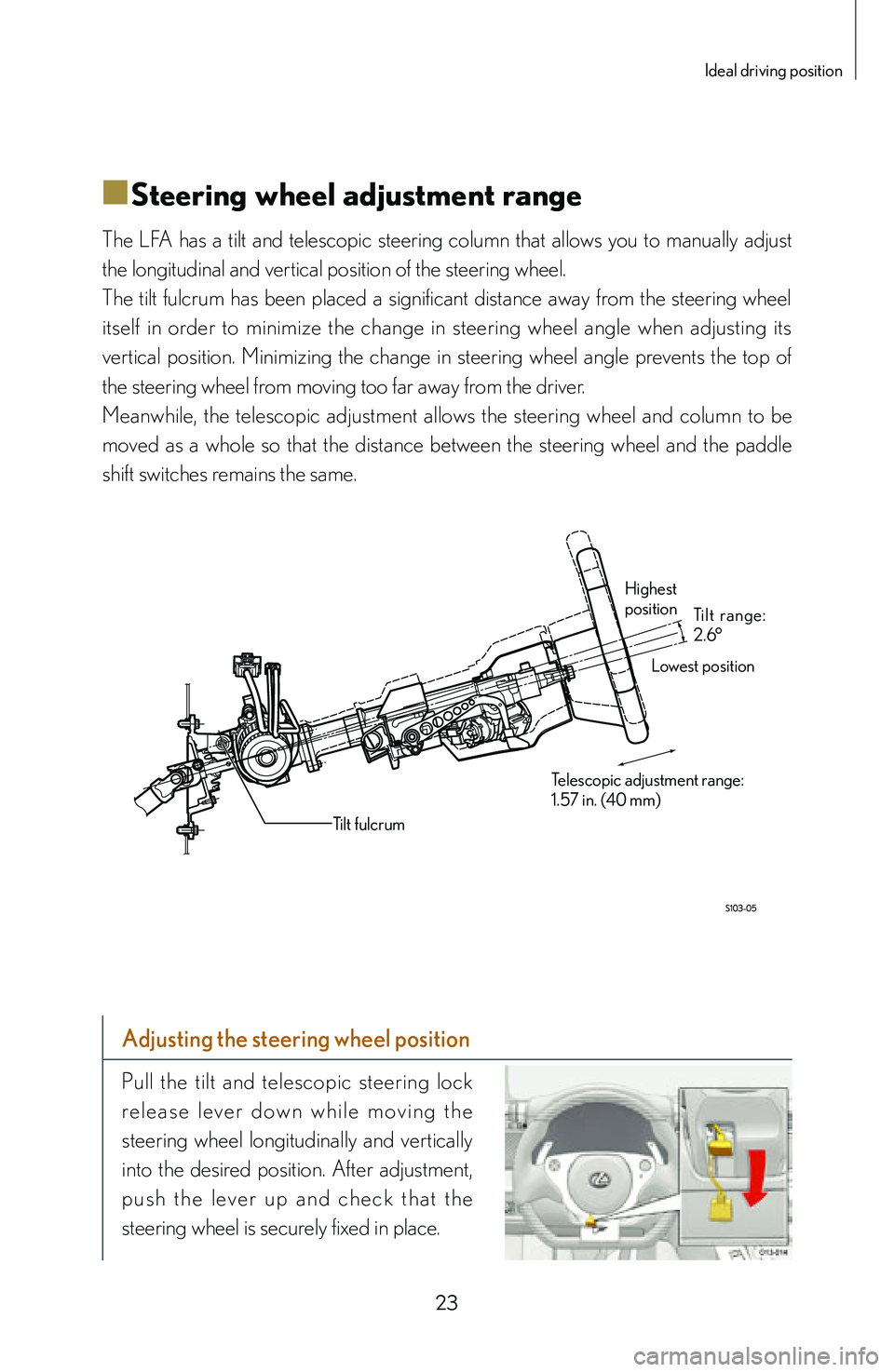
The LFA has a tilt and telescopic steering column that allows you to manually adjust
the longitudinal and vertical position of the steering wheel.
The tilt fulcrum has been placed a significant distance away from the steering wheel
itself in order to minimize the change in steering wheel angle when adjusting its
vertical position. Minimizing the change in steering wheel angle prevents the top of
the steering wheel from moving too far away from the driver.
Meanwhile, the telescopic adjustment allows the steering wheel and column to be
moved as a whole so that the distance between the steering wheel and the paddle
shift switches remains the same.
Highest
position
Lowest position
Telescopic adjustment range:
1.57 in. (40 mm) Tilt range:
2.6°
Tilt fulcrum
Adjusting the steering wheel position
Pull the tilt and telescopic steering lock
r e l e a s e l e v e r d o w n w h i l e m o v i n g t h e
steering wheel longitudinally and vertically
into the desired position. After adjustment,
p u s h t h e l eve r u p a n d c h e c k t h a t t h e
steering wheel is securely fixed in place.
Page 38 of 128

36
Shifting
With regards to the drivetrain, the steering wheel-mounted paddle shift switches
command the automated dry single-plate clutch and rear-mounted ASG (Automated
Sequential Gearbox) transaxle. This fully automated configuration allows the driver to
upshift (+) or downshift (-) while keeping both hands on the steering wheel.
When the driver initiates a gear change using the paddle shift switches, the ASG
computer automatically controls and coordinates clutch engagement, engine speed,
torque transfer and gear select and shift operations.
The engine-mounted dr y single-plate clutch and rear-mounted transaxle are
connected via torque tube to provide the direct feel of a manual gearbox.
The ECU manages gear changes to provide intuitive response to the driver ’s
a c c e l e r a t i o n d e m a n d s . D o i n g s o a l l o w s g e a r c h a n g e s t o b e c a r r i e d o u t
instantaneously, providing a nearly uninterrupted flow of power. The engine speed
is computer controlled on upshifts and downshifts in order to ensure smooth clutch
engagement.
Naturally, shifting can be accomplished manually via the paddle shift switches.
However, shifting can also be performed automatically in AUTO mode. Switching to a
different driving mode using the driving mode selector switch or operating the paddle
shift switches will resume manual operation.
When in a manually shifted driving mode, the shift speeds may be tailored to the
driver’s preferences. Using the shift speed selector, the shift speed can be adjusted in
7 stages to a minimum shift time of approximately 0.15 seconds.
Page 40 of 128

38
■
■Torque tube
Employing a torque tube to unite the front-mounted engine with the rear-mounted
transaxle creates an outstanding level of powertrain rigidity.
This aspect is essential in order to extract the most performance out of a vehicle. A
rigid powertrain reduces parasitic losses that occur from unwanted engine movement
and input from the wheels, allowing a greater amount of power to be sent to the road
and a more direct response.
Torque is transferred by means of an input shaft housed within the torque tube. This
fast-spinning shaft is mounted using rubber insulators with integrated bearings to
ensure quietness.
Torque tube
Rubber dampers with integrated bearings
Input shaft
Front counter gear Input shaft
A front counter gear is employed,
allowing the engine to be placed
closer to the ground. The engine
crankshaf t axis is lower to the
ground than the input shaft axis.
Crankshaft axis
Front counter gear
Page 46 of 128

44
Steering
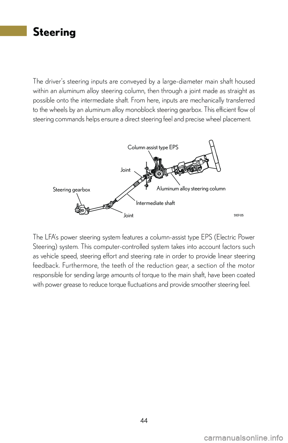
The driver’s steering inputs are conveyed by a large-diameter main shaft housed
within an aluminum alloy steering column, then through a joint made as straight as
possible onto the intermediate shaft. From here, inputs are mechanically transferred
to the wheels by an aluminum alloy monoblock steering gearbox. This efficient flow of
steering commands helps ensure a direct steering feel and precise wheel placement.
Joint Column assist type EPS
Aluminum alloy steering column
Intermediate shaft
Joint
Steering gearbox
The LFA’s power steering system features a column-assist type EPS (Electric Power
Steering) system. This computer-controlled system takes into account factors such
as vehicle speed, steering effort and steering rate in order to provide linear steering
feedback. Furthermore, the teeth of the reduction gear, a section of the motor
responsible for sending large amounts of torque to the main shaft, have been coated
with power grease to reduce torque fluctuations and provide smoother steering feel.
Page 47 of 128

45
Steering
■
■Steering wheel
The steering wheel features a flat-bottomed design that has 1.10 in. (28 mm) of the
lower half cut away. This reduces the steering wheel’s inertial moment and locates
the wheel’s rotational center and its center of gravity in almost the same place, almost
completely eliminating any imbalance within the steering wheel itself, reducing the
amount of steering fluctuations imparted by lateral and vertical forces. Ultimately
this provides the driver with a more natural and accurate steering feel. Furthermore,
the use of an aluminum alloy frame and hollow CFRP rim reduces the inertial force
generated by steering inputs.
H o l l o w C F R P
steering wheel rim
Center of rotation
Center of gravity
Turns lock-to-lock: 2.35
Aluminum alloy frame
Steering wheel center
Page 49 of 128

47
Steering
■
■Suspension
The LFA is equipped with a double wishbone front suspension and multi-link rear
suspension.
The front suspension features two independent lower arms that shorten the offset of
the virtual kingpin axis from the wheel centerline along with a slightly negative kingpin
offset in order to ensure ample stability under braking. Furthermore, the low offset
between the kingpin axis and wheel centerline allows for excellent road compliance
and outstanding stability.
Ground contact patch kingpin offset
Wheel centerline
Kingpin offset
Virtual kingpin axis
Regarding suspension adjustments:
The LFA is equipped with adjustable coil spring perches in order to allow for
any fine tuning needed to keep the geometry optimized at all times. Each LFA is
shipped from the factory with the suspension adjusted to the optimal settings.