2012 Lancia Voyager warning lights
[x] Cancel search: warning lightsPage 36 of 344

until it is fully open and then
press the switch again.
If the power sliding door en- counters multiple obstructions
within the same cycle, the sys-
tem will automatically stop, the
power sliding door motor will
make a clicking sound until the
door has no further movement.
This clicking sound can be
stopped by pulling the inside or
outside handle. If this condition
occurs, no damage is done to the
power sliding door motor. The
power sliding door must be
opened or closed manually.WARNING!
You, or others, could be injured if
caught in the path of the sliding
door. Make sure the door path is
clear before closing the door.
Power Sliding Side Door Open
Flash
The left and right exterior hazard
lights will flash for 12 seconds when
either sliding door is opened. This will alert other drivers in the area that
passenger(s) could be entering or ex-
iting the vehicle.
The Sliding Side Door Open Flash can
be enabled or disabled by performing
the following procedure:
1. Place the Key Fob in the ignition
switch.
2. Cycle the ignition switch from ON/
RUN to OFF five times ending in the
ON/RUN position
(do not start the
engine).
3. Within 10 seconds of the final
cycle, press the HAZARD switch ON.
4. A single chime will sound to signify
that you have successfully completed
the programming.
You can turn the feature back on by
repeating the previous procedure.
Power Sliding Side Door Master
Lock Switch
To provide a safer environment for
small children riding in the rear seats,
the second row sliding door switches
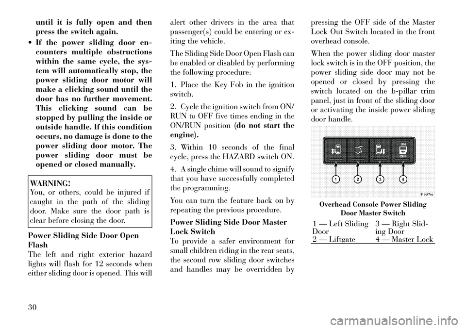
and handles may be overridden by pressing the OFF side of the Master
Lock Out Switch located in the front
overhead console.
When the power sliding door master
lock switch is in the OFF position, the
power sliding side door may not be
opened or closed by pressing the
switch located on the b-pillar trim
panel, just in front of the sliding door
or activating the inside power sliding
door handle.
Overhead Console Power Sliding
Door Master Switch1 — Left Sliding
Door 3 — Right Slid-
ing Door
2 — Liftgate 4 — Master Lock
30
Page 39 of 344

When the RKE transmitter button is
pressed and the Flash Lights feature
is enabled, the tail lights will flash and
several audible beeps will occur to
signal that the liftgate is opening or
closing.WARNING!
During power operation, personal
injury or cargo damage may occur.
Ensure the liftgate travel path is
clear. Make sure the liftgate is closed
and latched before driving away.
NOTE:
If anything obstructs the power liftgate while it is closing or
opening, the liftgate will auto-
matically reverse to the closed or open position, provided it meets
sufficient resistance.
There are also pinch sensors at- tached to the side of the liftgate
opening. Light pressure any-
where along these strips will
cause the liftgate to return to the
open position.
During power operation, whether liftgate is fully open or
fully closed, the liftgate chime
will beep several times indicat-
ing power operation is in prog-
ress.
The power liftgate must be in the full open or close positions for
any of the buttons to operate. If
the liftgate is not in the full open
or close positions, it must be
opened or closed manually.
If the liftgate release button is activated while the power lift-
gate is closing, the liftgate will
reverse to the full open position.
The power liftgate buttons will not operate if the shift lever is in
gear or the vehicle speed is
above 0 km/h. The power liftgate will not oper-
ate in temperatures below �24°C
or temperatures above 62°C. Be
sure to remove any buildup of
snow or ice from the liftgate be-
fore pressing any of the power
liftgate buttons.
If the power liftgate encounters multiple obstructions within the
same cycle, the system will auto-
matically stop and must be
opened or closed manually.
WARNING!
Driving with the liftgate open canallow poisonous exhaust gases
into your vehicle. You and your
passengers could be injured by
these fumes. Keep the liftgate
closed when you are operating the
vehicle.
If you are required to drive with
the liftgate open, make sure that
all windows are closed, and the
climate control blower switch is
set at high speed. Do not use the
recirculation mode.
Rear Power Liftgate Switch
33
Page 52 of 344

WARNING!(Continued)
Do not put anything on or around
the air bag covers or attempt to
open them manually. You may
damage the air bags and you
could be injured because the air
bags may no longer be functional.
The protective covers for the air
bag cushions are designed to open
only when the air bags are inflat-
ing.
Do not drill, cut or tamper with
the knee bolster (for versions/
markets, where provided) in any
way.
Do not mount any accessories to
the knee bolster (for versions/
markets, where provided) such as
alarm lights, stereos, citizen band
radios, etc.
Supplemental Seat-Mounted Side
Air Bags (SAB)
Supplemental Seat-Mounted Side Air
Bags (SAB) may provide enhanced
protection to help protect an occupant during a side impact. The SAB is
marked with an air bag label sewn
into the outboard side of the front
seats.
When the air bag deploys, it opens the
seam between the front and side of the
seat's trim cover. Each air bag deploys
independently; a left side impact de-
ploys the left air bag only and a right-
side impact deploys the right air bag
only.
Supplemental Side Air Bag
Inflatable Curtain (SABIC)
SABIC air bags may offer side-impact
and vehicle rollover protection to
front and rear seat outboard occu-pants in addition to that provided by
the body structure. Each air bag fea-
tures inflated chambers placed adja-
cent to the head of each outboard
occupant that reduce the potential for
side-impact head injuries. The SABIC
deploy downward, covering both win-
dows on the impact side.
NOTE:
Should a vehicle rollover occur,
the pretensioners and/or SAB
and SABIC air bags on both
sides of the vehicle may deploy.
Air Bag covers may not be obvi- ous in the interior trim, but they
will open during air bag deploy-
ment.
Being too close to the SAB and SABIC air bags during deploy-
ment could cause you to be se-
verely injured or killed.
The system includes side impact sen-
sors that are calibrated to deploy the
side air bags during impacts that re-
quire air bag occupant protection.
Supplemental Seat-Mounted Side Air Bag Label
46
Page 71 of 344

WARNING!(Continued)
Always make sure that objects
cannot fall into the driver footwell
while the vehicle is moving. Ob-
jects can become trapped under
the brake pedal and accelerator
pedal causing a loss of vehicle
control.
If required, mounting posts must
be properly installed, if not
equipped from the factory.
Failure to properly follow floor mat
installation or mounting can cause
interference with the brake pedal
and accelerator pedal operation
causing loss of control of the vehicle. Periodic Safety Checks You
Should Make Outside The
Vehicle
Tires
Examine tires for excessive tread wear
and uneven wear patterns. Check for
stones, nails, glass, or other objects
lodged in the tread or sidewall. In-
spect the tread for cuts and cracks.
Inspect sidewalls for cuts, cracks and
bulges. Check the wheel nuts for
tightness. Check the tires (including
spare) for proper cold inflation pres-
sure.
Lights
Have someone observe the operation
of exterior lights while you work the controls. Check turn signal and high
beam indicator lights on the instru-
ment panel.
Door Latches
Check for positive closing, latching,
and locking.
Fluid Leaks
Check area under vehicle after over-
night parking for fuel, engine coolant,
oil, or other fluid leaks. Also, if gaso-
line fumes are detected or if fuel,
power steering fluid, or brake fluid
leaks are suspected, the cause should
be located and corrected immediately.
65
Page 85 of 344

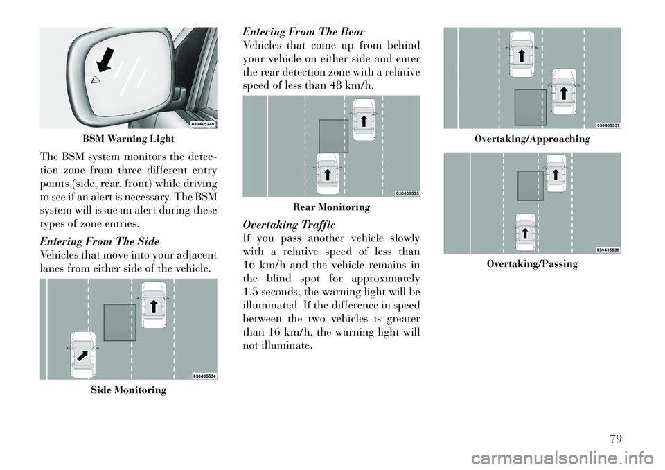
The BSM system monitors the detec-
tion zone from three different entry
points (side, rear, front) while driving
to see if an alert is necessary. The BSM
system will issue an alert during these
types of zone entries.
Entering From The Side
Vehicles that move into your adjacent
lanes from either side of the vehicle.Entering From The Rear
Vehicles that come up from behind
your vehicle on either side and enter
the rear detection zone with a relative
speed of less than 48 km/h.
Overtaking Traffic
If you pass another vehicle slowly
with a relative speed of less than
16 km/h and the vehicle remains in
the blind spot for approximately
1.5 seconds, the warning light will be
illuminated. If the difference in speed
between the two vehicles is greater
than 16 km/h, the warning light will
not illuminate.
BSM Warning LightSide Monitoring
Rear Monitoring
Overtaking/Approaching
Overtaking/Passing
79
Page 87 of 344

WARNING!
RCP is not a Back Up Aid system. It
is intended to be used to help a
driver detect an oncoming vehicle in
a parking lot situation. Drivers must
be careful when backing up, even
when using RCP. Always check care-
fully behind your vehicle, look be-
hind you, and be sure to check for
pedestrians, animals, other vehicles,
obstructions, and blind spots before
backing up. Failure to do so can
result in serious injury or death.
MODES OF OPERATION
Three selectable modes of operation
are available in the Electronic Vehicle
Information Center (EVIC). Refer to
"Electronic Vehicle Information Cen-
ter (EVIC)/Personal Settings
(Customer-Programmable Fea-
tures)” in “Understanding Your In-
strument Panel” for further informa-
tion. Blind Spot Alert
When operating in Blind Spot Alert
mode, the BSM system will provide a
visual alert in the appropriate side
view mirror based on a detected ob-
ject. However, when the system is op-
erating in RCP, the system will re-
spond with both visual and audible
alerts when a detected object is pres-
ent. Whenever an audible alert is re-
quested, the radio is muted.
Blind Spot Alert Lights/Chime
When operating in Blind Spot Alert
Lights/Chime mode, the BSM system
will provide a visual alert in the ap-
propriate side view mirror based on a
detected object. If the turn signal is
then activated, and it corresponds to
an alert present on that side of the
vehicle, an audible chime will also be
sounded. Whenever a turn signal and
detected object are present on the
same side at the same time, both the
visual and audio alerts will be issued.
In addition to the audible alert the
radio (if on) will also be muted.NOTE:
Whenever an audible alert is re-
quested by the BSM system, the
radio is also muted.
If the hazard flashers are on, the system will request the appro-
priate visual alert only.
When the system is in RCP, the
system shall respond with both vi-
sual and audible alerts when a de-
tected object is present. Whenever
an audible alert is requested, the
radio is also muted. Turn/hazard
signal status is ignored; the RCP
state always requests the chime.
Blind Spot Alert Off
When the BSM system is turned off
there will be no visual or audible
alerts from either the BSM or RCP
systems.
NOTE:
The BSM system will store the cur-
rent operating mode when the ve-
hicle is shut off. Each time the ve-
hicle is started the previously
stored mode will be recalled and
used.
81
Page 110 of 344

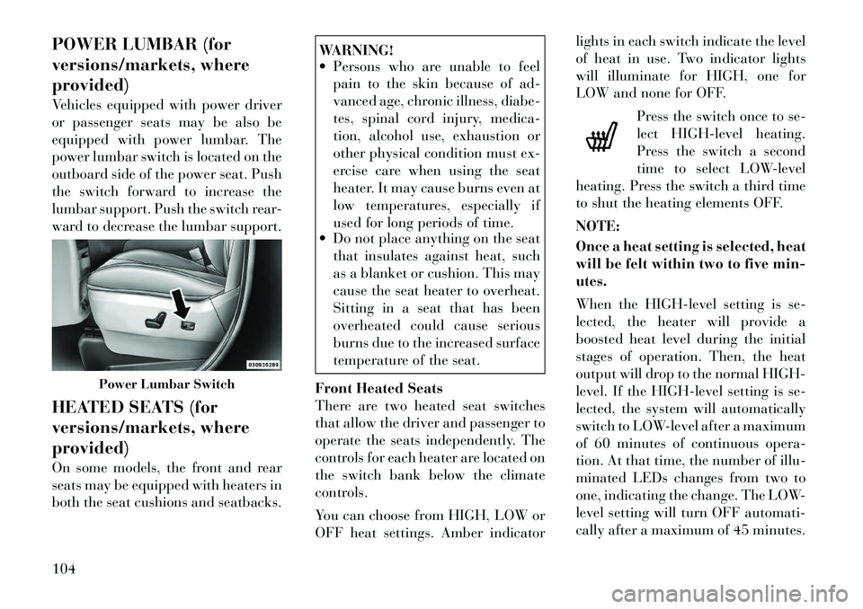
POWER LUMBAR (for
versions/markets, where
provided)
Vehicles equipped with power driver
or passenger seats may be also be
equipped with power lumbar. The
power lumbar switch is located on the
outboard side of the power seat. Push
the switch forward to increase the
lumbar support. Push the switch rear-
ward to decrease the lumbar support.
HEATED SEATS (for
versions/markets, where
provided)
On some models, the front and rear
seats may be equipped with heaters in
both the seat cushions and seatbacks.
WARNING!
Persons who are unable to feel pain to the skin because of ad-
vanced age, chronic illness, diabe-
tes, spinal cord injury, medica-
tion, alcohol use, exhaustion or
other physical condition must ex-
ercise care when using the seat
heater. It may cause burns even at
low temperatures, especially if
used for long periods of time.
Do not place anything on the seat
that insulates against heat, such
as a blanket or cushion. This may
cause the seat heater to overheat.
Sitting in a seat that has been
overheated could cause serious
burns due to the increased surface
temperature of the seat.
Front Heated Seats
There are two heated seat switches
that allow the driver and passenger to
operate the seats independently. The
controls for each heater are located on
the switch bank below the climate
controls.
You can choose from HIGH, LOW or
OFF heat settings. Amber indicator lights in each switch indicate the level
of heat in use. Two indicator lights
will illuminate for HIGH, one for
LOW and none for OFF.
Press the switch once to se-
lect HIGH-level heating.
Press the switch a second
time to select LOW-level
heating. Press the switch a third time
to shut the heating elements OFF.
NOTE:
Once a heat setting is selected, heat
will be felt within two to five min-
utes.
When the HIGH-level setting is se-
lected, the heater will provide a
boosted heat level during the initial
stages of operation. Then, the heat
output will drop to the normal HIGH-
level. If the HIGH-level setting is se-
lected, the system will automatically
switch to LOW-level after a maximum
of 60 minutes of continuous opera-
tion. At that time, the number of illu-
minated LEDs changes from two to
one, indicating the change. The LOW-
level setting will turn OFF automati-
cally after a maximum of 45 minutes.
Power Lumbar Switch
104
Page 125 of 344

2. Move to the front of the vehicle and
look inside the center of the hood
opening. Locate, then push the safety
catch lever downward while raising
the hood at the same time.
Use the hood prop rod to secure the
hood in the open position.
CAUTION!
To prevent possible damage, do not
slam the hood to close it. Lower the
hood until it is open approximately
30 cm and then drop it. This should
secure both latches. Never drive
your vehicle unless the hood is fully
closed, with both latches engaged.WARNING!
Be sure the hood is fully latched
before driving your vehicle. If the
hood is not fully latched, it could
open when the vehicle is in motion
and block your vision. Failure to
follow this warning could result in
serious injury or death.
LIGHTS
All of the lights, except the Hazard
Warning lights, headlight high beams
and flash-to-pass, are controlled by
switches to the left of the steering
column on the instrument panel. INTERIOR LIGHTING
Interior lights are turned on when a
door or liftgate is opened, the Remote
Keyless Entry (RKE) transmitter is
activated, or when the dimmer con-
trol is moved to the extreme top.
The interior lights will automatically
turn off in approximately 10 minutes
for the first activation and 90 seconds
every activation thereafter until the
engine is started, if one of the follow-
ing occur:
A door, sliding door or the liftgate is
left open
Any overhead reading light is left on
Hood Release
Safety Catch Location
Headlight Switch With Halo Control Assembly
119