Page 17 of 385
23
Your vehicle at a glance
INSTRUMENT PANEL OVERVIEW
OMD010002N
1. Instrument cluster.............................4-43
2. Horn .................................................4-39
3. Driver’s front air bag .........................3-46
4. Light control/Turn signals .................4-62
5. Wiper/Washer ...................................4-66
6. Ignition switch*/
Engine start/stop button ...............5-5/5-8
7. Clock ................................................4-95
8. Audio* ...............................................4-98
9. Hazard warning flasher
switch .........................................4-60,6-2
10. Climate control system ..........4-71,4-80
11. Shift lever ...............................5-12,5-15
12. Parking brake .................................5-22
13. Passenger’s front air bag ...............3-46
14. Glove box .......................................4-91
* : if equipped
Page 112 of 385

433
Features of your vehicle
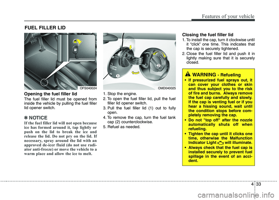
Opening the fuel filler lid
The fuel filler lid must be opened from
inside the vehicle by pulling the fuel filler
lid opener switch.
✽ ✽
NOTICE
If the fuel filler lid will not open because
ice has formed around it, tap lightly or
push on the lid to break the ice and
release the lid. Do not pry on the lid. If
necessary, spray around the lid with an
approved de-icer fluid (do not use radi-
ator anti-freeze) or move the vehicle to a
warm place and allow the ice to melt.
1. Stop the engine.
2. To open the fuel filler lid, pull the fuel
filler lid opener switch.
3. Pull the fuel filler lid (1) out to fully
open.
4. To remove the cap, turn the fuel tank
cap (2) counterclockwise.
5. Refuel as needed.
Closing the fuel filler lid
1. To install the cap, turn it clockwise until
it “click” one time. This indicates that
the cap is securely tightened.
2. Close the fuel filler lid and push it in
lightly making sure that it is securely
closed.
FUEL FILLER LID
OMD040025
WARNING - Refueling
If pressurized fuel sprays out, it
can cover your clothes or skin
and thus subject you to the risk
of fire and burns. Always remove
the fuel cap carefully and slowly.
If the cap is venting fuel or if you
hear a hissing sound, wait until
the condition stops before com-
pletely removing the cap.
Do not "top off" after the nozzle
automatically shuts off when
refueling.
Tighten the cap until it clicks one
time, otherwise the Malfunction
Indicator Light will illuminate.
Always check that the fuel cap is
installed securely to prevent fuel
spillage in the event of an acci-
dent.
OFS040024
Page 193 of 385

Features of your vehicle
114 4
Clock
Type A
This allows you to set the time format
and the clock.
Time format: Change the time format
between the “12h” and “24h”.
Setting the clock
- Press ▲or ▼on the left side of the
clock to set the hour.
- Press ▲or ▼on the right side of the
clock to set the minute.
- If you set the [Time format] to [12h],
set the [am] or [pm].
Type B
This allows you to set the time format
and the summer time.
Time format: Change the time format
between the “12h” and “24h”.
Summer time: Set the summer time
between the “On” and “Off ”. The unit
sets the clock automatically by detect-
ing the summer time whether it is the
summer time season or not. Even
though the summer time is set to "On",
the unit sets the clock to normal time
(not +1 hour) when it's not summer
time season.CAUTION
Use the power outlet only when
the engine is running and remove
the accessory plug after use.
Using the accessory plug for pro-
longed periods of time with the
engine off could cause the bat-
tery to discharge.
Only use 12V electric accessories
which are less than 10A in elec-
tric capacity.
Adjust the air-conditioner or
heater to the lowest operating
level when using the power outlet.
Close the cover when not in use.
Some electronic devices can cause
electronic interference when
plugged into a vehicle’s power out-
let. These devices may cause
excessive audio static and malfunc-
tions in other electronic systems or
devices used in your vehicle.
WARNING
Do not put a finger or a foreign ele-
ment (pin, etc.) into a power outlet
and do not touch with a wet hand.
You may get an electric shock.
WARNING
Do not adjust the clock while driv-
ing. You may lose your steering
control and cause severe personal
injury or accidents.
Page 204 of 385
4125
Features of your vehicle
12. Right rotary (TUNE)
Rotate it clockwise/counterclockwise.
Searches the previous or next radio
frequency.
- Manual tuning
Skips a track/file up/down in all list
screen.
ZOOM IN/ ZOOM OUT
- Rotate to change the map scale on
the map screen.
Repeat voice guidance
Press to repeat the voice guidance.
13. PHONE ( )
Use to enable Bluetooth Hands-Free
Phone.
14. NAV
Press to enter a destination menu.
Various methods for entering a destina-
tion are available.
15. MAP
Press to display the current location map
screen.
16. CD indicator light (CD-IN)
When a disc is inserted, the indicator is
illuminated.
17. Clock ( )
Press to display the digital/analog
clock and outside temperature in
power on/off status.
Press and hold to move to the [Clock]
menu.
Page 278 of 385
613
What to do in an emergency
Removing and storing the spare
tire
Turn the tire hold-down wing bolt
counterclockwise.
Store the tire in the reverse order of
removal.
To prevent the spare tire and tools
from “rattling” while the vehicle is in
motion, store them properly.Changing tires
1. Park on a level surface and apply
the parking brake firmly.
2. Shift the shift lever into R
(Reverse) with manual transaxle
or P (Park) with automatic
transaxle.
3. Activate the hazard warning flash-
er.
(Continued)
Do not start or run the engine
while the vehicle is on the
jack.
Do not allow anyone to remain
in the vehicle while it is on the
jack.
Make sure any children pres-
ent are in a secure place away
from the road and from the
vehicle to be raised with the
jack.
OFS060007OED066033
Page 279 of 385
What to do in an emergency
14 6
4. Remove the wheel lug nut wrench,
jack, jack handle, and spare tire
from the vehicle.
5. Block both the front and rear of the
wheel that is diagonally opposite
the jack position.6. Insert the screwdriver into the
groove of the wheel cap and pry
gently to remove the wheel cap (If
equipped).
7. Loosen the wheel lug nuts coun-
terclockwise one turn each, but do
not remove any nut until the tire
has been raised off the ground.
WARNING- Changing a tire
To prevent vehicle movement
while changing a tire, always
set the parking brake fully,
and always block the wheel
diagonally opposite the wheel
being changed.
We recommend that the
wheels of the vehicle be
blocked, and that no person
remain in a vehicle that is
being jacked.
OFS060009OFS062010
Page 280 of 385

615
What to do in an emergency
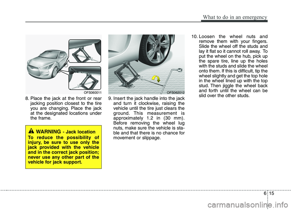
8. Place the jack at the front or rear
jacking position closest to the tire
you are changing. Place the jack
at the designated locations under
the frame.9. Insert the jack handle into the jack
and turn it clockwise, raising the
vehicle until the tire just clears the
ground. This measurement is
approximately 1.2 in (30 mm).
Before removing the wheel lug
nuts, make sure the vehicle is sta-
ble and that there is no chance for
movement or slippage.10. Loosen the wheel nuts and
remove them with your fingers.
Slide the wheel off the studs and
lay it flat so it cannot roll away. To
put the wheel on the hub, pick up
the spare tire, line up the holes
with the studs and slide the wheel
onto them. If this is difficult, tip the
wheel slightly and get the top hole
in the wheel lined up with the top
stud. Then jiggle the wheel back
and forth until the wheel can be
slid over the other studs.
WARNING- Jack location
To reduce the possibility of
injury, be sure to use only the
jack provided with the vehicle
and in the correct jack position;
never use any other part of the
vehicle for jack support.
OFS060011OFS062012
Page 281 of 385

What to do in an emergency
16 6
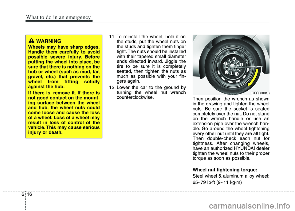
11. To reinstall the wheel, hold it on
the studs, put the wheel nuts on
the studs and tighten them finger
tight. The nuts should be installed
with their tapered small diameter
ends directed inward. Jiggle the
tire to be sure it is completely
seated, then tighten the nuts as
much as possible with your fin-
gers again.
12. Lower the car to the ground by
turning the wheel nut wrench
counterclockwise.
Then position the wrench as shown
in the drawing and tighten the wheel
nuts. Be sure the socket is seated
completely over the nut. Do not stand
on the wrench handle or use an
extension pipe over the wrench han-
dle. Go around the wheel tightening
every other nut until they are all tight.
Then double-check each nut for
tightness. After changing wheels,
have an authorized HYUNDAI dealer
tighten the wheel nuts to their proper
torque as soon as possible.
Wheel nut tightening torque:
Steel wheel & aluminum alloy wheel:
65~79 lb·ft (9~11 kg·m)
WARNING
Wheels may have sharp edges.
Handle them carefully to avoid
possible severe injury. Before
putting the wheel into place, be
sure that there is nothing on the
hub or wheel (such as mud, tar,
gravel, etc.) that prevents the
wheel from fitting solidly
against the hub.
If there is, remove it. If there is
not good contact on the mount-
ing surface between the wheel
and hub, the wheel nuts could
come loose and cause the loss
of a wheel. Loss of a wheel may
result in loss of control of the
vehicle. This may cause serious
injury or death.
OFS060013