Page 292 of 385
627
What to do in an emergency
When towing your vehicle in an emer-
gency without wheel dollies :
1. Set the ignition switch in the ACC posi-
tion.
2. Place the shift lever in N (Neutral).
3. Release the parking brake.
Removable towing hook
(if equipped)
1. Open the tailgate, and remove the tow-
ing hook from the tool case.
2. Remove the hole cover pressing the
lower part of the cover on the bumper.
3. Install the towing hook by turning it
clockwise into the hole until it is fully
secured.
4. Remove the towing hook and install
the cover after use.
Emergency towing (if equipped)
If towing is necessary, we recommend
you to have it done by an authorized
Hyundai dealer or a commercial tow
truck service.
CAUTION
Failure to place the transaxle shift
lever in N (Neutral) may cause inter-
nal damage to the transaxle.
OFS060017
OFS060018
OFS060019
■Type A
■Type B
Page 317 of 385
723
Maintenance
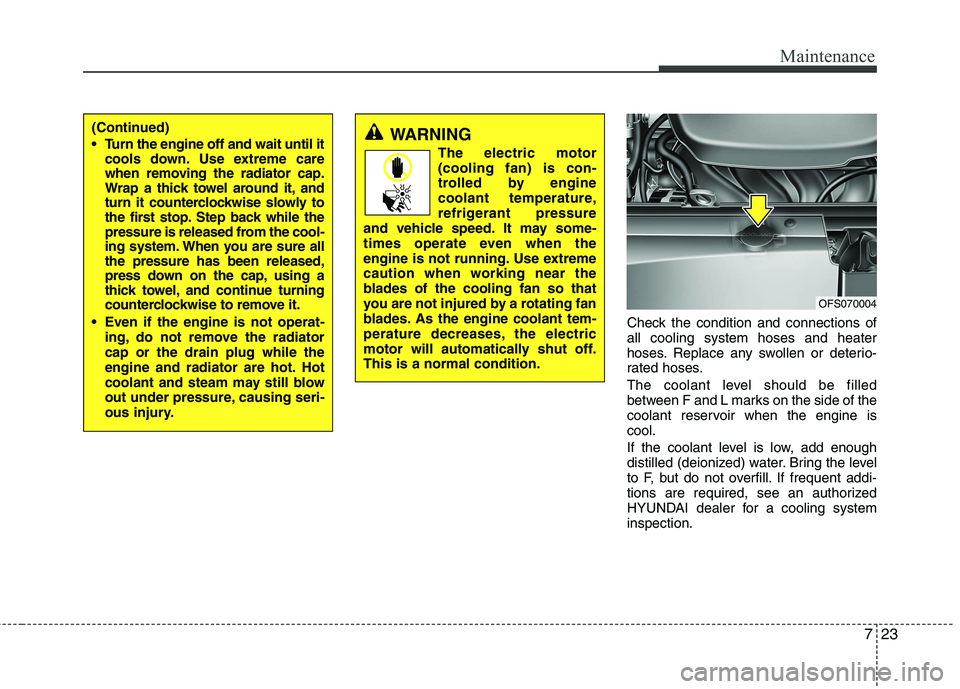
Check the condition and connections of
all cooling system hoses and heater
hoses. Replace any swollen or deterio-
rated hoses.
The coolant level should be filled
between F and L marks on the side of the
coolant reservoir when the engine is
cool.
If the coolant level is low, add enough
distilled (deionized) water. Bring the level
to F, but do not overfill. If frequent addi-
tions are required, see an authorized
HYUNDAI dealer for a cooling system
inspection.
OFS070004
(Continued)
Turn the engine off and wait until it
cools down. Use extreme care
when removing the radiator cap.
Wrap a thick towel around it, and
turn it counterclockwise slowly to
the first stop. Step back while the
pressure is released from the cool-
ing system. When you are sure all
the pressure has been released,
press down on the cap, using a
thick towel, and continue turning
counterclockwise to remove it.
Even if the engine is not operat-
ing, do not remove the radiator
cap or the drain plug while the
engine and radiator are hot. Hot
coolant and steam may still blow
out under pressure, causing seri-
ous injury.WARNING
The electric motor
(cooling fan) is con-
trolled by engine
coolant temperature,
refrigerant pressure
and vehicle speed. It may some-
times operate even when the
engine is not running. Use extreme
caution when working near the
blades of the cooling fan so that
you are not injured by a rotating fan
blades. As the engine coolant tem-
perature decreases, the electric
motor will automatically shut off.
This is a normal condition.
Page 328 of 385
Maintenance
34 7
Reset items
Items should be reset after the battery
has been discharged or the battery has
been disconnected.
Auto up/down window (See section 4)
Sunroof (See section 4)
Trip computer (See section 4)
Climate control system
(See section 4)
Clock (See section 4)
Audio (See section 4)WARNING
Before performing maintenance
or recharging the battery, turn off
all accessories and stop the
engine.
The negative battery cable must
be removed first and installed
last when the battery is discon-
nected.
Operation related to the battery
should be done in an authorized
HYUNDAI dealer.
WARNING- Recharging
battery
When recharging the battery,
observe the following precautions:
The battery must be removed
from the vehicle and placed in an
area with good ventilation.
Do not allow cigarettes, sparks,
or flame near the battery.
Watch the battery during charg-
ing, and stop or reduce the charg-
ing rate if the battery cells begin
gassing (boiling) violently or if
the temperature of the electrolyte
of any cell exceeds 120°F (49°C).
Wear eye protection when check-
ing the battery during charging.
Disconnect the battery charger in
the following order.
1. Turn off the battery charger main
switch.
2. Unhook the negative clamp from
the negative battery terminal.
3. Unhook the positive clamp from
the positive battery terminal.
Page 347 of 385
753
Maintenance
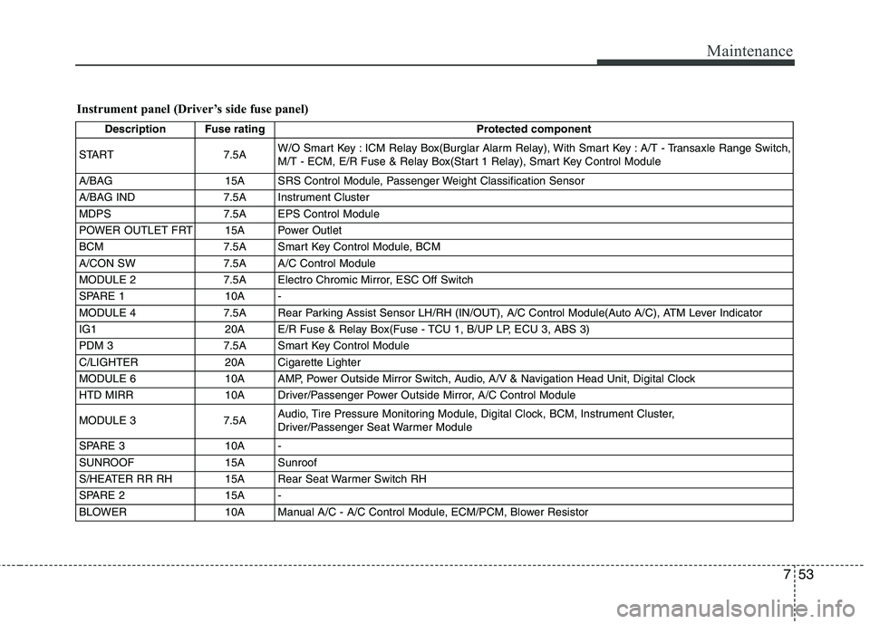
Instrument panel (Driver’s side fuse panel)
Description Fuse rating Protected component
START 7.5AW/O Smart Key : ICM Relay Box(Burglar Alarm Relay), With Smart Key : A/T - Transaxle Range Switch,
M/T - ECM, E/R Fuse & Relay Box(Start 1 Relay), Smart Key Control Module
A/BAG 15A SRS Control Module, Passenger Weight Classification Sensor
A/BAG IND 7.5A Instrument Cluster
MDPS 7.5A EPS Control Module
POWER OUTLET FRT 15A Power Outlet
BCM 7.5A Smart Key Control Module, BCM
A/CON SW 7.5A A/C Control Module
MODULE 2 7.5A Electro Chromic Mirror, ESC Off Switch
SPARE 1 10A -
MODULE 4 7.5A Rear Parking Assist Sensor LH/RH (IN/OUT), A/C Control Module(Auto A/C), ATM Lever Indicator
IG1 20A E/R Fuse & Relay Box(Fuse - TCU 1, B/UP LP, ECU 3, ABS 3)
PDM 3 7.5A Smart Key Control Module
C/LIGHTER 20A Cigarette Lighter
MODULE 6 10A AMP, Power Outside Mirror Switch, Audio, A/V & Navigation Head Unit, Digital Clock
HTD MIRR 10A Driver/Passenger Power Outside Mirror, A/C Control Module
MODULE 3 7.5AAudio, Tire Pressure Monitoring Module, Digital Clock, BCM, Instrument Cluster,
Driver/Passenger Seat Warmer Module
SPARE 3 10A -
SUNROOF 15A Sunroof
S/HEATER RR RH 15A Rear Seat Warmer Switch RH
SPARE 2 15A -
BLOWER 10A Manual A/C - A/C Control Module, ECM/PCM, Blower Resistor
Page 348 of 385
Maintenance
54 7
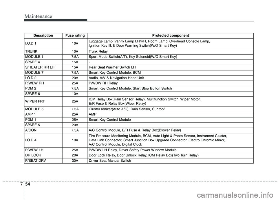
Description Fuse rating Protected component
I.O.D 1 10ALuggage Lamp, Vanity Lamp LH/RH, Room Lamp, Overhead Console Lamp,
Ignition Key Ill. & Door Warning Switch(W/O Smart Key)
TRUNK 10A Trunk Relay
MODULE 1 7.5A Sport Mode Switch(A/T), Key Solenoid(W/O Smart Key)
SPARE 4 15A -
S/HEATER RR LH 15A Rear Seat Warmer Switch LH
MODULE 7 7.5A Smart Key Control Module, BCM
I.O.D 2 20A Audio, A/V & Navigation Head Unit
P/WDW RH 25A P/WDW RH Relay
PDM 2 7.5A Smart Key Control Module, Start Stop Button Switch
SPARE 6 10A -
WIPER FRT 25AICM Relay Box(Rain Sensor Relay), Multifunction Switch, Wiper Motor,
E/R Fuse & Relay Box(Wiper Relay)
MODULE 5 7.5A Cluster Ionizer(Auto A/C), Rain Sensor, Sunroof
AMP 1 25A AMP
PDM 1 25A Smart Key Control Module
SPARE 5 20A -
A/CON 7.5A A/C Control Module, E/R Fuse & Relay Box(Blower Relay)
I.O.D 4 10ATire Pressure Monitoring Module, BCM, Auto Light & Photo Sensor, Instrument Cluster,
Data Link Connector, Smart Junction Box Upgrade Connector, Electro Chromic Mirror,
A/C Control Module, Digital Clock
P/WDW LH 25A P/WDW LH Relay, Driver Safety Power Window Module
DR LOCK 20A Door Lock Relay, Door Unlock Relay, ICM Relay Box(Two Turn Relay)
P/SEAT DRV 30A Driver Seat Manual Switch
Page 352 of 385
Maintenance
58 7
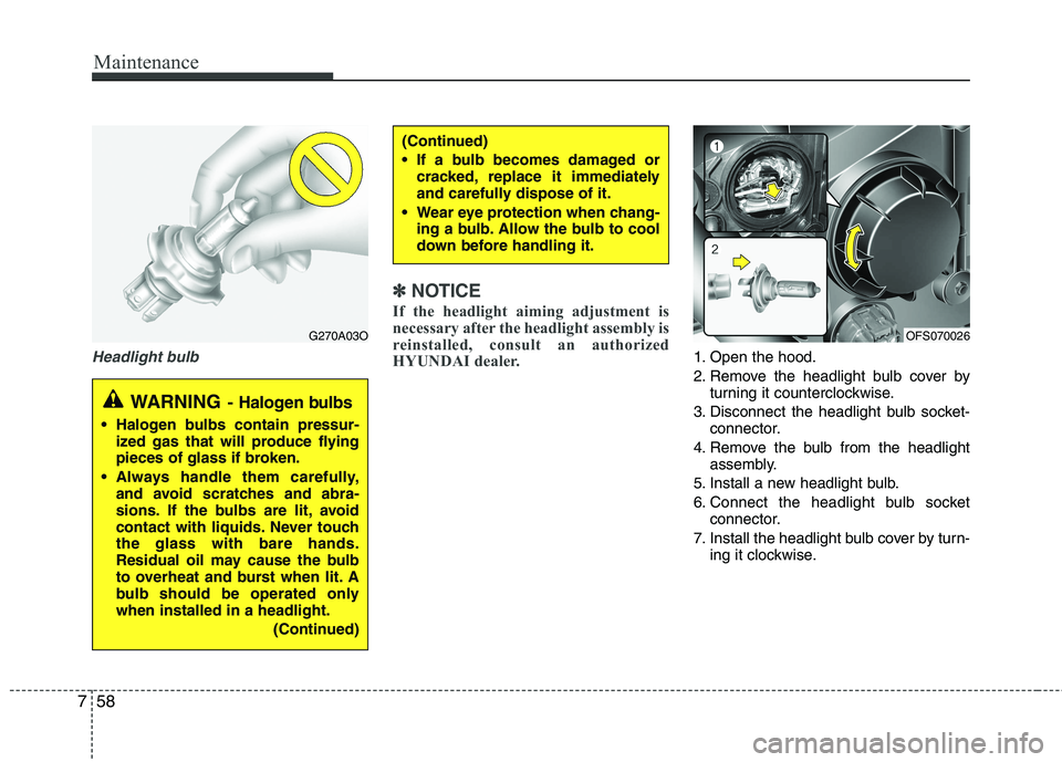
Headlight bulb
✽
✽
NOTICE
If the headlight aiming adjustment is
necessary after the headlight assembly is
reinstalled, consult an authorized
HYUNDAI dealer.
1. Open the hood.
2. Remove the headlight bulb cover by
turning it counterclockwise.
3. Disconnect the headlight bulb socket-
connector.
4. Remove the bulb from the headlight
assembly.
5. Install a new headlight bulb.
6. Connect the headlight bulb socket
connector.
7. Install the headlight bulb cover by turn-
ing it clockwise.
(Continued)
If a bulb becomes damaged or
cracked, replace it immediately
and carefully dispose of it.
Wear eye protection when chang-
ing a bulb. Allow the bulb to cool
down before handling it.
G270A03O
WARNING- Halogen bulbs
Halogen bulbs contain pressur-
ized gas that will produce flying
pieces of glass if broken.
Always handle them carefully,
and avoid scratches and abra-
sions. If the bulbs are lit, avoid
contact with liquids. Never touch
the glass with bare hands.
Residual oil may cause the bulb
to overheat and burst when lit. A
bulb should be operated only
when installed in a headlight.
(Continued)
OFS070026
Page 353 of 385
759
Maintenance
Position light (if equipped)
If the light does not operate, have the
vehicle checked by an authorized
HYUNDAI dealer.
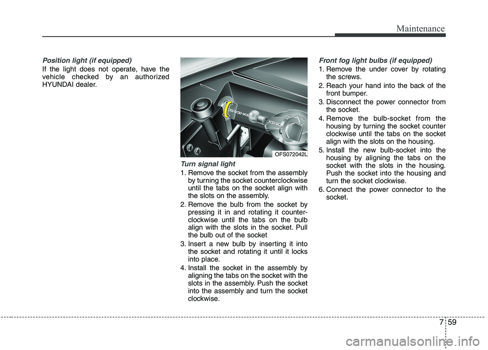
Turn signal light
1. Remove the socket from the assembly
by turning the socket counterclockwise
until the tabs on the socket align with
the slots on the assembly.
2. Remove the bulb from the socket by
pressing it in and rotating it counter-
clockwise until the tabs on the bulb
align with the slots in the socket. Pull
the bulb out of the socket
3. Insert a new bulb by inserting it into
the socket and rotating it until it locks
into place.
4. Install the socket in the assembly by
aligning the tabs on the socket with the
slots in the assembly. Push the socket
into the assembly and turn the socket
clockwise.
Front fog light bulbs (if equipped)
1. Remove the under cover by rotating
the screws.
2. Reach your hand into the back of the
front bumper.
3. Disconnect the power connector from
the socket.
4. Remove the bulb-socket from the
housing by turning the socket counter
clockwise until the tabs on the socket
align with the slots on the housing.
5. Install the new bulb-socket into the
housing by aligning the tabs on the
socket with the slots in the housing.
Push the socket into the housing and
turn the socket clockwise.
6. Connect the power connector to the
socket.
OFS072042L
Page 355 of 385
761
Maintenance
4. Remove the socket from the assembly
by turning the socket counterclockwise
until the tabs on the socket align with the
slots on the assembly.
5. Remove the bulb from the socket.
6. Insert a new bulb by inserting it into the
socket and pushing or rotating it until it
locks into place.
7. Install the socket in the assembly by
aligning the tabs on the socket with the
slots in the assembly. Push the socket
into the assembly and turn the socket
clockwise.
8. Reinstall the light assembly to the body
of the vehicle.
9. Tighten the screws.
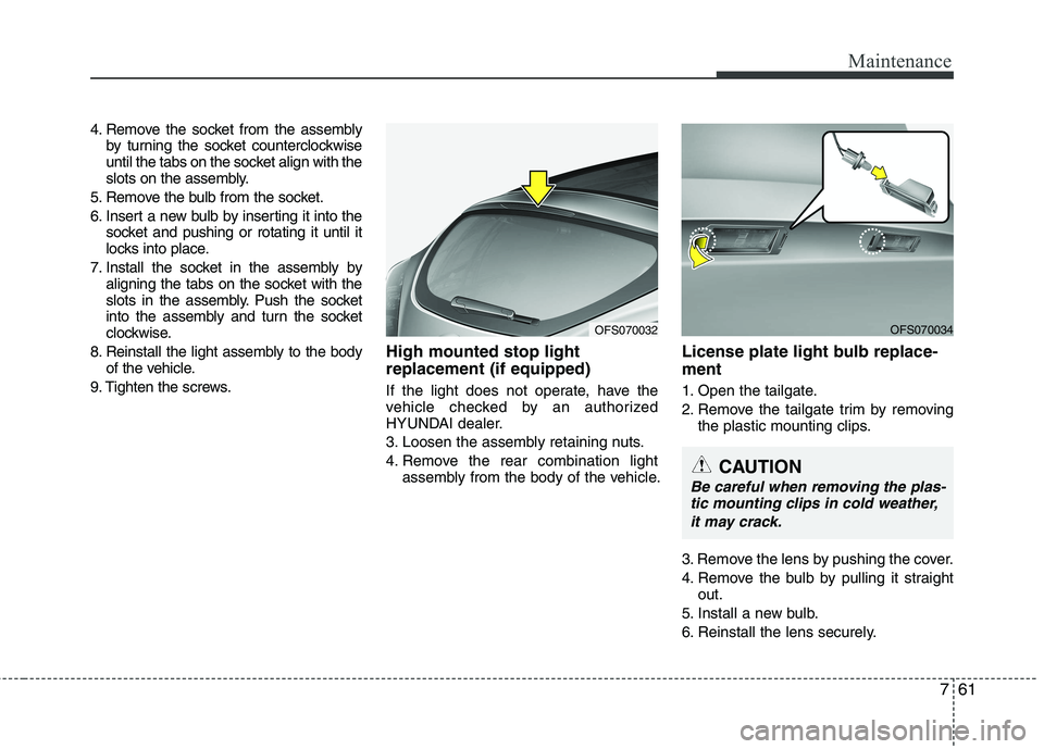
High mounted stop light
replacement (if equipped)
If the light does not operate, have the
vehicle checked by an authorized
HYUNDAI dealer.
3. Loosen the assembly retaining nuts.
4. Remove the rear combination light
assembly from the body of the vehicle.
License plate light bulb replace-
ment
1. Open the tailgate.
2. Remove the tailgate trim by removing
the plastic mounting clips.
3. Remove the lens by pushing the cover.
4. Remove the bulb by pulling it straight
out.
5. Install a new bulb.
6. Reinstall the lens securely.
OFS070032OFS070034
CAUTION
Be careful when removing the plas-
tic mounting clips in cold weather,
it may crack.