2012 FORD F650 wheel
[x] Cancel search: wheelPage 184 of 306
Brake system - general inspection
Your vehicle is equipped with non-asbestos brake linings. However,
exposure to excessive amounts of brake material (whether asbestos or
non-asbestos, fiberglass, mineral wool, aramid or carbon) may be a
serious health hazard.
Note:Persons handling brake linings should follow all precautions listed
below:
WARNING:
1. Always wear a respirator approved by the National Institute of
Occupational Studies of Health (NIOSH) or Mine Safety and Appliance
(MSA) during all brake service procedures. Wear the respirator from
removal of the wheels through assembly.
2.Neveruse compressed air or dry brushing to clean brake parts or
assemblies.
3. Clean brake parts and assemblies in open air. During assembly,
carefully place all parts on the floor to avoid getting dust in the air. Use
an industrial vacuum cleaner with a HEPA filter system to clean dust
from the brake drums, backing plates and other brake parts. After using
the vacuum, remove any remaining dust with a rag soaked in water and
wrung until nearly dry.
4.Neveruse compressed air or dry sweeping to clean the work area.
Use an industrial vacuum cleaner with a HEPA filter system and rags
soaked in water until wrung until nearly dry. Dispose of used rags with
care to avoid getting dust in the air. Use an approved respirator when
emptying vacuum cleaners and handling used rags.
5.Worker clean-up:Wash your hands before eating, drinking or
smoking. Vacuum your work clothes after use and then launder them
separately, without shaking them, to prevent fiber dust getting into the
air.
Air brakes
Inspection and adjustment:Establish a regular schedule for periodic
cleaning, lubrication and adjustment inspection based on vehicle use.
Exact maintenance intervals are difficult to predetermine since vehicles
are used in a wide variety of applications and conditions; if you are
uncertain of the proper schedule for your vehicle, contact your dealer.
Maintenance and Specifications
184
2012 F-650/750(f67)
Supplement, 2nd Printing
USA(fus)
Page 187 of 306
Brake lines, hoses and fittings:Inspect these components every
4,000 miles (6,000 km):
•Lines for kinks, dents, corrosion or rupture.
•Hoses for abrasions, kinks, soft spots or rupture, collapse, cracks,
twists or loose frame supports. When replacing a hose, be sure there
is adequate clearance to the hose to avoid an abrasion to the new
hose.
•All connections for leaks.
•Repair or replace brake line tubes, hoses or fittings as required.
Driveline parking brake
Parking brake adjustment should only be performed by a qualified
technician, and in accordance with the instructions in the service
manual.
WARNING:Use wheel chocks and exercise caution when
inspecting under the vehicle. A vehicle roll-away could result in
property damage, personal injury or death.
Catalytic converter (diesel engine)
If your diesel engine is equipped with a catalytic converter, it is
important to review the maintenance schedule to ensure proper
functioning of the catalytic converter. Also, take precautions not to
damage the catalytic converter when servicing your engine or storing
your vehicle.
Note:If your vehicle is equipped with a catalytic converter/muffler,do
notblend waste oil with diesel fuel. Operate only on ultra low sulfur
(less than 15 parts per million sulfur) diesel fuel with a cetane value of
45 or higher.
Diesel exhaust fluid (DEF), Diesel particulate filter (DPF) and Select
catalyst reduction (SCR) system
Refer to your engine operator’s manual for information regarding DEF,
DPF and SCR system service.
Air induction system
Once each year, perform a complete inspection of the air induction
system. In areas where road salt is used, the inspection consists of
disassembling the joints of each aluminum component and inspecting for
salt build-up, presence of chlorine that can cause aluminum particles to
flake off and enter the engine combustion chambers.
Maintenance and Specifications
187
2012 F-650/750(f67)
Supplement, 2nd Printing
USA(fus)
Page 222 of 306

and/or additions of aftermarket devices can reduce the
effectiveness of the system, as well as cause damage to the
exhaust system and/or engine. Any modifications may also
invalidate the vehicle and/or engine warranties. See the vehicle
and engine warranty guides for more information.
The inlet holes in the side of the assembly are functional. These holes
allow outside air to be drawn into the outlet assembly. The holes need to
be kept clear of mud and other foreign material to maintain proper
functionality of the system. One way to keep the holes clear is to spray
the outlet assembly with a hose when washing the vehicle. Failure to
keep the functional holes clear of foreign material may result in the holes
becoming blocked or plugged.Blocked/plugged holes or
modification/removal of the outlet assembly could result in
elevated exhaust temperatures which may result in
vehicle/property damage and/or personal injury.
NOISE EMISSIONS – EXTERIOR
In order to comply with the federal exterior noise regulations, your
vehicle may be equipped with noise emission items. Depending on the
vehicle configuration, it may have all or some of the following items:
Air Intake System:Inspect air cleaner; do not alter its location. Do not
alter inlet and outlet piping.
Body:Inspect wheel well splash shields, cab shields and underhood
insulation for deterioration, dislocation and orientation.
Cooling System:
•Inspect fan for damage to blades; if damaged, replace with the
recommended parts. Inspect for fan-to-shroud interference and any
damage to shroud such as cracks and holes.
•Do not change fan ratio or alter fan spacer dimensions and positions.
•Inspect fan clutch for proper operation; make sure the fan is
disengaged when cooling of the engine is not required.
•Inspect radiator shutters (if equipped) for proper operation; the
shutters should be open during normal operating temperatures.
Engine:Valve covers and block covers are made to damp-out engine
mechanical noise and, if needed, should be replaced with recommended
parts. Check for mechanical isolations.
Transmission Enclosure:Inspect for cracks, holes and tears. Clean any
deposits such as oil, dirt and stones.
Maintenance and Specifications
222
2012 F-650/750(f67)
Supplement, 2nd Printing
USA(fus)
Page 230 of 306
Supporting your vehicle for service
Prepare the vehicle for service repairs by doing the following:
1. Park the vehicle on a level concrete floor.
2. Set the parking brake and block the wheels to prevent the vehicle
from moving.
3. Select a jack with a rated capacity sufficient to lift and hold up the
vehicle.
4. Raise the vehicle with the jack applied to the axle(s). DO NOT use the
bumper as a lifting point.
5. Support the vehicle with floor stands under the axle(s). If the axle or
the suspension are being serviced, support the vehicle with floor stands
under the frame side-members, preferably between the axles.
WARNING:Do not use a jack when working under a vehicle. It
may give way, causing the vehicle to fall and result in property
damage, personal injury or death. Always use floor stands to support
the vehicle.
FRAME AND TOW HOOKS
Your vehicle’s chassis is manufactured with frame rails of either HSLA
steel or heat-treated steel; each must be handled in a specific manner to
ensure maximum service life. Consult the service manual or your dealer
before attempting frame repair or modification.
It is important, particularly on vehicles where the tow hooks are used
frequently, to inspect the front and rear tow hooks for damage or a loose
mounting.
SPRING U-BOLT CHECKS
Check U-bolt nuts and re-torque every 36,000 miles (58,000 km) after
initial 1,000 miles (1,600 km) re-torque. The U-bolt and nut threads and
seats should be cleaned and lubricated to ensure peak condition when
re-torqued.
U-bolt nut torque
Suspension ft-lb N•m
Front axle – 8500 lb (3856 kg) 180-200 244-271
Front axles – 10000 lb (4536 kg) and higher 260-300 353-407
Maintenance and Specifications
230
2012 F-650/750(f67)
Supplement, 2nd Printing
USA(fus)
Page 232 of 306

Checking the rear axle lubricant level
1. Park the vehicle on level ground.
2. Set the parking brake and shift into N (Neutral) (automatic
transmission) or 1 (First) (manual transmission) and turn the engine off.
3. Clean any dirt from around the rear axle filler plug.
4. Remove the filler plug and inspect the lubricant level; it should be up
to the bottom of the filler plug opening.
5. Add lubricant, if necessary, through the filler plug opening.
6. Clean and install the filler plug securely.
Draining and refilling the rear axle lubricant
1. Drain the rear axle while the lubricant is warm.
2. Park the vehicle on level ground.
3. Set the parking brake and shift into N (Neutral) (automatic
transmission) or 1 (First) (manual transmission) and turn the engine off.
4. Clean any dirt from around the rear axle filler and drain plugs.
5. Remove the filler and drain plugs and drain the lubricant into a
suitable container. Dispose of all used automotive fluids in a responsible
manner following your local authorized standards.
6. Clean and install the drain plug securely.
7. Add lubricant through the filler plug opening.
8. Clean and install the filler plug securely.
WHEELS
General
Wheel bearings should be inspected, lubricated and adjusted at regular
intervals. This is especially important if operating in deep sand, mud or
water. Refer toLubricant specificationsin this chapter.
Mount wheel balance weights on the dome-side of the wheel only; failure
to do so may result in loss of wheel weight and/or damage to brakes or
wheels.
Important:Remember to replace the wheel air valves when the road
tires are replaced at the end of their useful life.
Maintenance and Specifications
232
2012 F-650/750(f67)
Supplement, 2nd Printing
USA(fus)
Page 233 of 306
Oil-lubricated front wheel bearings
During normal vehicle duty cycle, the lube and air inside the hub/wheel
cavity expands and, if not vented, causes pressure build-up that could
cause accelerated seal wear. There are two venting methods that can be
used to prevent pressure build-up:
•a slit or small hole in the rubber check vent or
•the window
Normal maintenance
Over a period of time, if not routinely cleaned, a slight film of oil can
collect dirt around the rubber fill plug and face, which could appear to
be a leak. Routine cleaning ensures that the lube level can be easily
observed through the clear window as intended. In situations where the
window is clean on the outside but discolored on the inside, the lube
level may be checked by inserting a finger through the rubber check
vent hole.
The specified lube level for a clear window type hubcaps is from the
minimum line to + 5/16 inch above the minimum line. If the lube level
should suddenly drop dramatically below the minimum level, see the
Workshop Manualfor diagnostic procedure.
Installation, tightening and alignment
Verify the threads on studs and nuts are clean to permit correct torque
when installing wheels. The mounting surfaces of rims, wheels, spacer
rings and clamps must be free of dirt, rust, lubricants or damage. Use a
wire brush to clean the mounting contact surfaces. Do not use lubricant
on threads.
Check the rim or wheel for proper alignment after it has been properly
tightened. Rotate the wheel with a piece of chalk attached to a steady,
firm surface, and placed to just barely clear the outside surface of the
tire bead seat; this procedure points out the high spot. A high spot does
not necessarily mean that the lug nuts have been unevenly tightened,
but could be the result of a bent wheel.
Use the following installation procedure:
1. Slide inner rear or front tire and wheel in position over studs and push
it back as far as possible. Use care so that the threads on studs are not
damaged.
Maintenance and Specifications
233
2012 F-650/750(f67)
Supplement, 2nd Printing
USA(fus)
Page 234 of 306
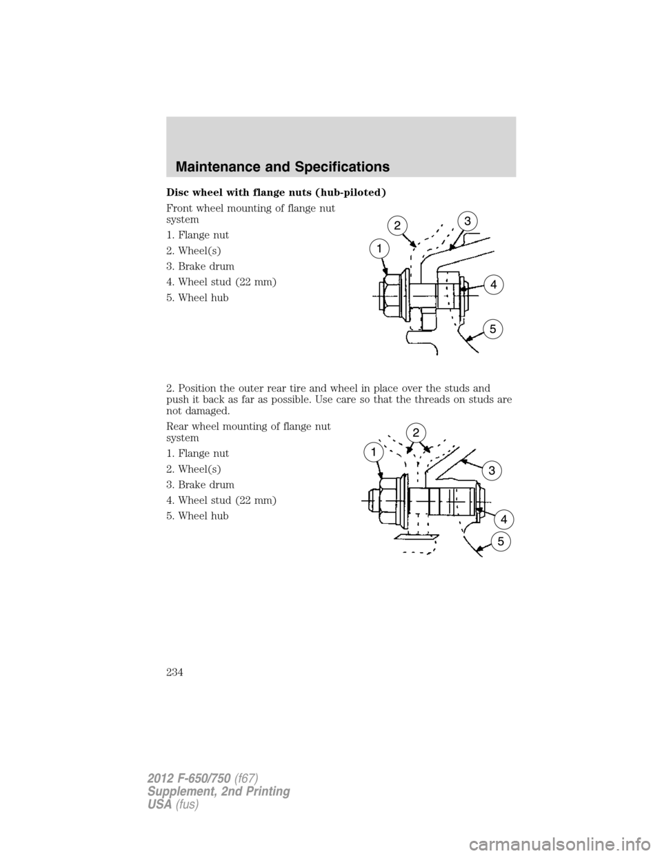
Disc wheel with flange nuts (hub-piloted)
Front wheel mounting of flange nut
system
1. Flange nut
2. Wheel(s)
3. Brake drum
4. Wheel stud (22 mm)
5. Wheel hub
2. Position the outer rear tire and wheel in place over the studs and
push it back as far as possible. Use care so that the threads on studs are
not damaged.
Rear wheel mounting of flange nut
system
1. Flange nut
2. Wheel(s)
3. Brake drum
4. Wheel stud (22 mm)
5. Wheel hub
Maintenance and Specifications
234
2012 F-650/750(f67)
Supplement, 2nd Printing
USA(fus)
Page 235 of 306
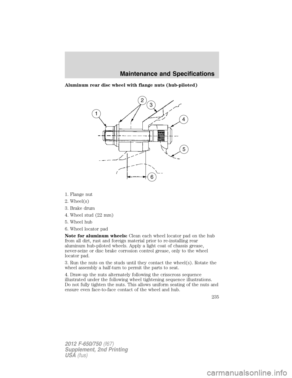
Aluminum rear disc wheel with flange nuts (hub-piloted)
1. Flange nut
2. Wheel(s)
3. Brake drum
4. Wheel stud (22 mm)
5. Wheel hub
6. Wheel locator pad
Note for aluminum wheels:Clean each wheel locator pad on the hub
from all dirt, rust and foreign material prior to re-installing rear
aluminum hub-piloted wheels. Apply a light coat of chassis grease,
never-seize or disc brake corrosion control grease, only to the wheel
locator pad.
3. Run the nuts on the studs until they contact the wheel(s). Rotate the
wheel assembly a half-turn to permit the parts to seat.
4. Draw-up the nuts alternately following the crisscross sequence
illustrated under the following wheel tightening sequence illustrations.
Do not fully tighten the nuts. This allows uniform seating of the nuts and
ensure even face-to-face contact of the wheel and hub.
1
6
5
4
32
Maintenance and Specifications
235
2012 F-650/750(f67)
Supplement, 2nd Printing
USA(fus)