2012 FORD F650 brake light
[x] Cancel search: brake lightPage 115 of 306
WARNING:Block the wheels to help prevent the vehicle from
moving.
WARNING:Unexpected and possibly sudden vehicle movement
may occur if these precautions are not taken.
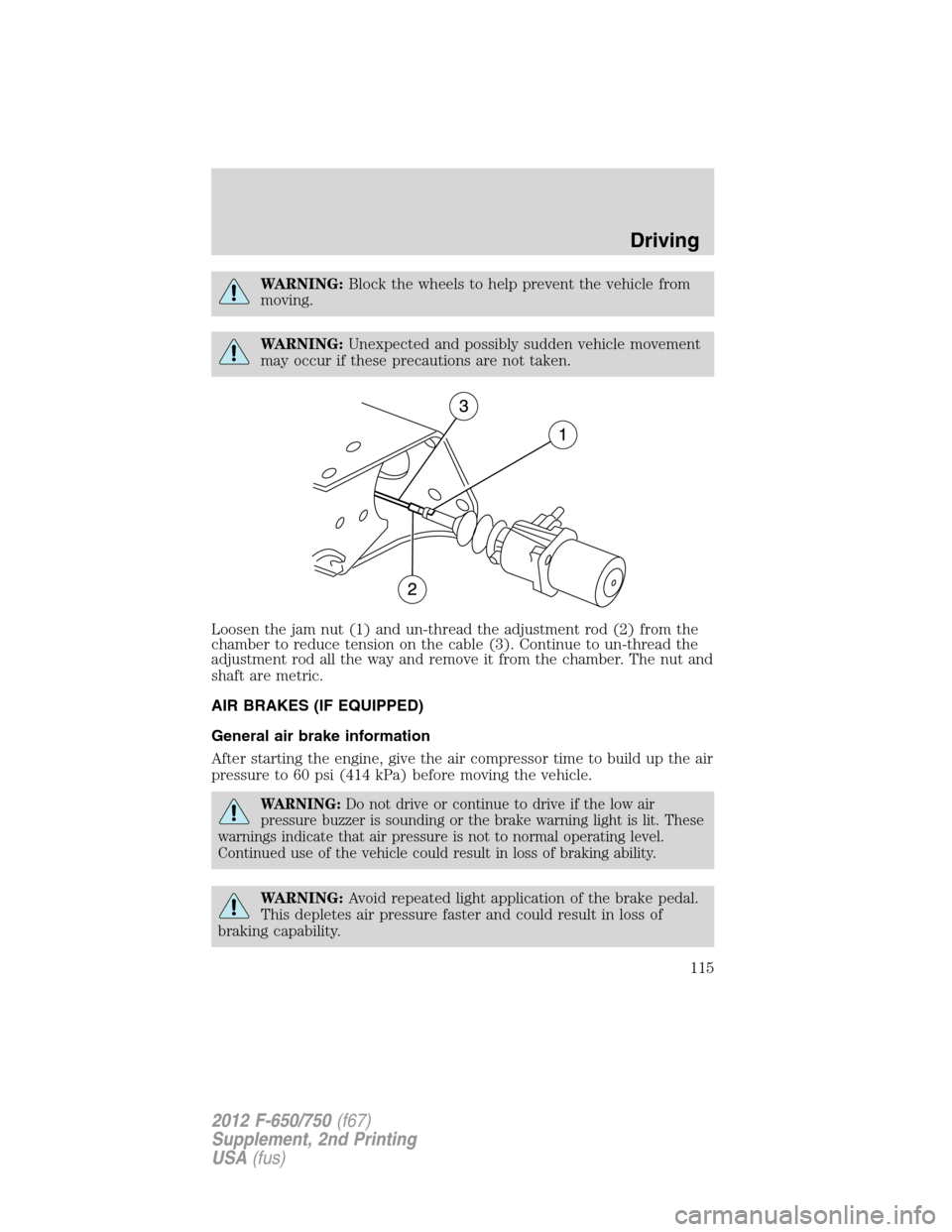
Loosen the jam nut (1) and un-thread the adjustment rod (2) from the
chamber to reduce tension on the cable (3). Continue to un-thread the
adjustment rod all the way and remove it from the chamber. The nut and
shaft are metric.
AIR BRAKES (IF EQUIPPED)
General air brake information
After starting the engine, give the air compressor time to build up the air
pressure to 60 psi (414 kPa) before moving the vehicle.
WARNING:Do not drive or continue to drive if the low air
pressure buzzer is sounding or the brake warning light is lit. These
warnings indicate that air pressure is not to normal operating level.
Continued use of the vehicle could result in loss of braking ability.
WARNING:Avoid repeated light application of the brake pedal.
This depletes air pressure faster and could result in loss of
braking capability.
Driving
115
2012 F-650/750(f67)
Supplement, 2nd Printing
USA(fus)
Page 116 of 306

Periodically check the air pressure
gauge while driving. Pressure should
range between approximately
100–125 psi (690–862 kPa). The air
compressor governor cut-in and
cut-out pressure settings are set at
the factory and are not adjustable.
When air pressure is insufficient
(below 60 psi [414 kPa]), a warning
light illuminates and a buzzer
sounds when the ignition is in the
on position.
This condition may be caused by excessive brake applications depleting
the system air pressure. If this condition occurs, stop driving the vehicle
until the compressor has fully recharged the air system.
WARNING:Do not move the vehicle when the air pressure is
insufficient because the brake system may be inoperative.
Select a gear ratio to help slow your vehicle before descending grades.
Supplement with brakes as required to safely slow the vehicle and avoid
overspeeding the engine.
Air chamber stroke indication
Air chamber push rods have orange stroke indicator markers that warn
when the braking system requires adjustment or repair. The orange
stripe is painted on the air chamber push rod at the slack adjuster stroke
dimension which requires service when visible during brake application.
Air brake inspection and adjustment or repairs should be performed by a
qualified service technician in accordance with the instructions in the
service manual.
Driving
116
2012 F-650/750(f67)
Supplement, 2nd Printing
USA(fus)
Page 119 of 306
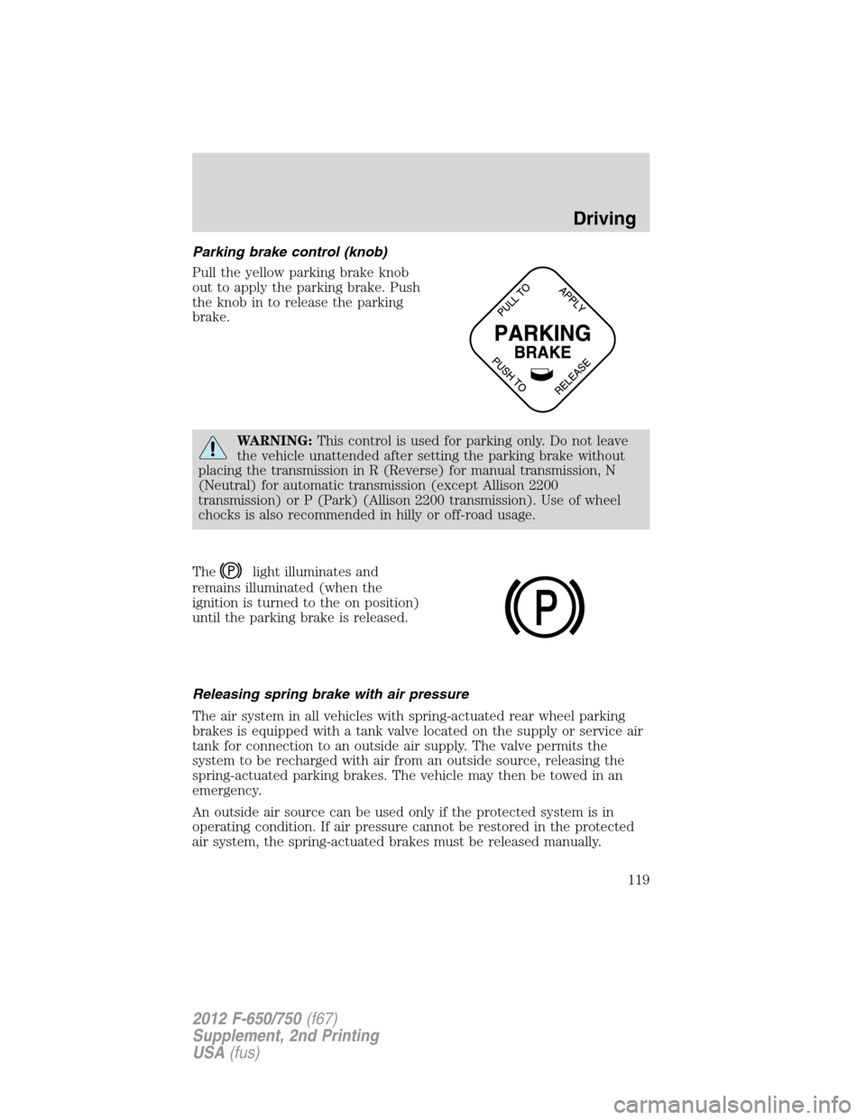
Parking brake control (knob)
Pull the yellow parking brake knob
out to apply the parking brake. Push
the knob in to release the parking
brake.
WARNING:This control is used for parking only. Do not leave
the vehicle unattended after setting the parking brake without
placing the transmission in R (Reverse) for manual transmission, N
(Neutral) for automatic transmission (except Allison 2200
transmission) or P (Park) (Allison 2200 transmission). Use of wheel
chocks is also recommended in hilly or off-road usage.
The
light illuminates and
remains illuminated (when the
ignition is turned to the on position)
until the parking brake is released.
Releasing spring brake with air pressure
The air system in all vehicles with spring-actuated rear wheel parking
brakes is equipped with a tank valve located on the supply or service air
tank for connection to an outside air supply. The valve permits the
system to be recharged with air from an outside source, releasing the
spring-actuated parking brakes. The vehicle may then be towed in an
emergency.
An outside air source can be used only if the protected system is in
operating condition. If air pressure cannot be restored in the protected
air system, the spring-actuated brakes must be released manually.
P
Driving
119
2012 F-650/750(f67)
Supplement, 2nd Printing
USA(fus)
Page 122 of 306
Note:Manual transmissions should be downshifted to the lowest gear
possible, without exceeding the maximum RPM limit of the engine. This
maximizes the exhaust brake’s retarding effect.
Note:Exhaust brakes operate effectively with automatic transmissions,
but performance varies with engine speed and the gear selected by the
transmission.
Note:Installing an exhaust or auxiliary brake does not necessarily
protect the engine from exceeding maximum governed speed. The
primary brakes should be used to make sure the engine never exceeds
maximum governed speed under any conditions.
WARNING:The exhaust brake is not recommended for use on
slippery or low traction road surfaces. Under these conditions a
loss of vehicle control could occur.
Exhaust brake operating characteristics
When you remove your feet from both the accelerator and clutch pedals
and the exhaust brake switch is in the on position, the exhaust brake is
activated. The following conditions should exist if the brake is operating
properly:
•A slight change in the sound of the engine when the exhaust brake is
activated.
•A smooth braking effect; do not expect a retarding effect similar to
sudden, hard application of the service brakes.
•The retarding force possibly felt acting against your body when the
brake is applied, depending on the grade and vehicle load. The brake’s
retarding force is actually preventing the vehicle from going much
faster.
•Engine temperature remains in the normal operating range.
•During a descent, the tachometer usually shows a drop in engine RPM
depending on the grade and the vehicle load.
•Road speed usually decreases when the exhaust brake is applied
during a descent, except when the vehicle is carrying a heavy load or
the grade is extremely steep. In these instances, you may need to
apply the service brakes occasionally.
Driving
122
2012 F-650/750(f67)
Supplement, 2nd Printing
USA(fus)
Page 127 of 306

Actuation of trailer park (emergency) or tractor bobtail position
To actuate the trailer brakes only, pull out the trailer air supply knob (1).
The trailer brakes are now applied whether emergency or spring brakes
are used on the trailer.
This mode is also used when the tractor or truck with trailer is used
during bobtail operation.
ANTI-LOCK BRAKE SYSTEM (ABS)
Your vehicle is equipped with an anti-lock braking system (ABS). This
system helps you maintain steering control during emergency stops by
keeping the brakes from locking. Noise from the ABS pump motor and
brake pedal pulsation may be observed during ABS braking; any
pulsation or mechanical noise you may feel or hear is normal.
When hard braking is required, apply continuous force on the brake
pedal. Do not pump the brake pedal since this reduces the effectiveness
of the ABS and increases your vehicle’s stopping distance. The ABS
activates immediately, allowing you to retain steering control during hard
braking and on slippery surfaces. However, the ABS does not decrease
stopping distance.
ABS warning light
The
light in the instrument cluster momentarily illuminates when the
ignition is turned on. If the light does not illuminate during start up,
remains on after the vehicle reaches 5–10 mph (8–16 km/h), or flashes,
the ABS may be disabled and may need to be serviced.
Even when the ABS is disabled, normal braking is still effective. If
the
light illuminates with the parking brake released, have your
brake system serviced immediately.
1
2
Driving
127
2012 F-650/750(f67)
Supplement, 2nd Printing
USA(fus)
Page 128 of 306
TRACTION CONTROL (IF EQUIPPED)
Your vehicle may be equipped with a traction control system which helps
you maintain stability and steerability, especially on slippery road
surfaces such as snow- or ice-covered roads and gravel roads, by
reducing engine power and/or selectively applying the rear brakes.
Note:The traction control system does not apply the brakes when
vehicle speed is above 25 mph (40 km/h).
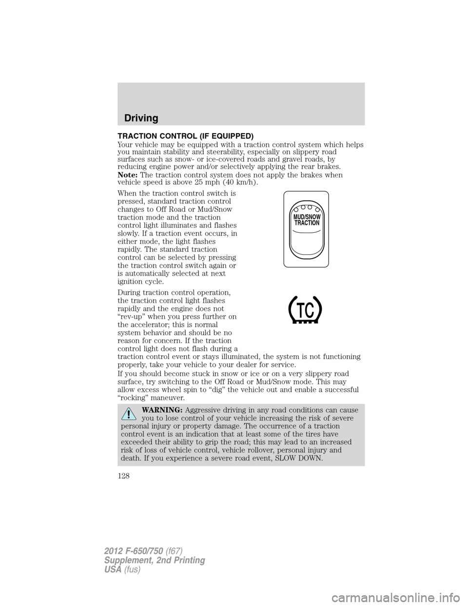
When the traction control switch is
pressed, standard traction control
changes to Off Road or Mud/Snow
traction mode and the traction
control light illuminates and flashes
slowly. If a traction event occurs, in
either mode, the light flashes
rapidly. The standard traction
control can be selected by pressing
the traction control switch again or
is automatically selected at next
ignition cycle.
During traction control operation,
the traction control light flashes
rapidly and the engine does not
“rev-up” when you press further on
the accelerator; this is normal
system behavior and should be no
reason for concern. If the traction
control light does not flash during a
traction control event or stays illuminated, the system is not functioning
properly, take your vehicle to your dealer for service.
If you should become stuck in snow or ice or on a very slippery road
surface, try switching to the Off Road or Mud/Snow mode. This may
allow excess wheel spin to “dig” the vehicle out and enable a successful
“rocking” maneuver.
WARNING:Aggressive driving in any road conditions can cause
you to lose control of your vehicle increasing the risk of severe
personal injury or property damage. The occurrence of a traction
control event is an indication that at least some of the tires have
exceeded their ability to grip the road; this may lead to an increased
risk of loss of vehicle control, vehicle rollover, personal injury and
death. If you experience a severe road event, SLOW DOWN.
MUD/SNOW
TRACTION
Driving
128
2012 F-650/750(f67)
Supplement, 2nd Printing
USA(fus)
Page 130 of 306
Tractor-trailer connections
WARNING:To reduce the risk of personal injury, use extreme
caution when making brake and light connections. Inclement
weather and accumulated road contamination deposits on handhold
and stepping surfaces require extra care to avoid slip and falls. Provide
adequate lighting of working areas.
WARNING:Do not climb on the back of the tractor unless it
has been provided with a deck plate and handholds. Use a
three-point stance when climbing up and down from a deck plate. Do
not jump from the vehicle. Whenever possible, make all connections
while standing on the ground.
Connecting and disconnecting a trailer with air suspension and air
suspension dump switch (if equipped)
When connecting to a trailer:
•Press the lower portion of the dump switch to exhaust air from the air
suspension system.
•After making the connection to the trailer, press the upper portion of
the dump switch, then raise the landing gear.
When disconnecting the trailer:
•
Lower the landing gear, then press the lower portion of the dump switch.
•Disconnect the brake hoses, trailer-side and rear light connectors,
then pull the release lever on the fifth-wheel.
The upper portion of the dump switch must be pressed before operating
with a trailer or operating in the bobtail mode.
Suspension conversions
It is not recommended, or approved, that suspension conversions be
performed. However, it is understood that, on occasion, aftermarket add-on
suspensions are installed by others on the truck chassis which allow
operator control for weight transfer from other axles (i.e., air lift axles).
WARNING:When operating a loaded vehicle, the driver must
keep all adjustable axles on the ground at all times, supporting
their share of the vehicle’s load. Failure to do so can overload other
axles, tires, wheels, springs, steering components, brakes and frames,
resulting in early component failure, loss of vehicle control, possible
property damage and personal injury.
Driving
130
2012 F-650/750(f67)
Supplement, 2nd Printing
USA(fus)
Page 133 of 306

several transmission upshifts and downshifts; during this learning
process, slightly firmer shifts may occur. After this learning process,
normal shift feel and shift scheduling will resume.
P (Park)
This position locks the transmission and prevents the rear wheels from
turning.
To put your vehicle in gear:
1. Start the engine
2. Press the brake pedal
3. Move the gearshift lever into the desired gear
To put your vehicle in P (Park):
1. Come to a complete stop
2. Move the gearshift lever and securely latch it in P (Park)
WARNING:Always set the parking brake fully and make sure
the gearshift is latched in P (Park). Turn the ignition to the off
position and remove the key whenever you leave your vehicle.
R (Reverse)
With the gearshift lever in R (Reverse), the vehicle will move backward.
Always come to a complete stop before shifting into and out of R
(Reverse).
N (Neutral)
With the gearshift lever in N (Neutral), the vehicle can be started and is
free to roll. Hold the brake pedal down while in this position.
D (Drive)
This is the normal driving position for the best fuel economy. This
position allows automatic upshifts and downshifts through gears one
through six.
4 (Fourth)
This position allows automatic upshifts and downshifts in gears one
through four.
2 (Second)
Use 2 (Second) to start-up on slippery roads or to provide additional
engine braking on downgrades.
Driving
133
2012 F-650/750(f67)
Supplement, 2nd Printing
USA(fus)