Page 63 of 160
DRIVING THROUGH WATER
If driving through deep or standing
water is unavoidable, proceed very
slowly. Never drive through water
that is higher than the bottom of
the wheel rims (for cars) or the
bottom of the hubs (for trucks).
When driving through water, traction or brake capability may be limited.
Also, water may enter your engine’s air intake and severely damage your
engine or your vehicle may stall.Driving through deep water where
the transmission vent tube is submerged may allow water into the
transmission and cause internal transmission damage.
Once through the water, always dry the brakes by moving your
vehicle slowly while applying light pressure on the brake pedal.
Wet brakes do not stop the vehicle as quickly as dry brakes.
Driving
63
2012 Motorhome(mot)
Supplement, 2nd Printing
USA(fus)
Page 70 of 160
Fuse/Relay
LocationFuse Amp
RatingProtected circuits
F1 — Not used
F2 — Not used
F3 — Not used
F4 10A BTSI
F5 — Not used
F6 — Not used
F7 — Not used
F8 — Not used
F9 — Not used
F10 — Not used
F11 — Not used
F12 — Not used
Power distribution box
The power distribution box is located in the engine compartment. The
power distribution box contains high-current fuses that protect your
vehicle’s main electrical systems from overloads.
WARNING:Always disconnect the battery before servicing high
current fuses.
WARNING:To reduce risk of electrical shock, always replace
the cover to the power distribution box before reconnecting the
battery or refilling fluid reservoirs.
If the battery has been disconnected and reconnected, refer to the
Batterysection of theMaintenance and Specificationschapter.
Roadside Emergencies
70
2012 Motorhome(mot)
Supplement, 2nd Printing
USA(fus)
Page 71 of 160
The high-current fuses are coded as follows.
Fuse/Relay
LocationFuse Amp
RatingProtected Circuits
1 5A* Power brake assist module -
Hydromax
2 10A* A/C compressor clutch
3 20A* A/C clutch relay coil, Mass air
flow sensor (MAFS) with intake
air temperature (IAT), Vapor
management valve, Engine heated
exhaust gas oxygen (HEGO)
sensor #11, HEGO #21, Catalyst
monitor sensor (CMS)
4 5A* Powertrain control module (PCM)
memory
5 20A* PCM power
19 29
18 28
17 27
16 26
15 25
14 24
13
11 12
910
78
56
34
1223
22
21
20
R6
R5
R4
R3
R2
R1DIODE2
DIODE1
Roadside Emergencies
71
2012 Motorhome(mot)
Supplement, 2nd Printing
USA(fus)
Page 74 of 160

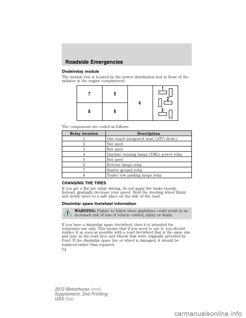
Diode/relay module
The module box is located by the power distribution box in front of the
radiator in the engine compartment.
The components are coded as follows:
Relay location Description
1 One touch integrated start (ATO diode)
2 Not used
3 Not used
4 Daytime running lamps (DRL) power relay
5 Not used
6 Reverse lamps relay
7 Starter ground relay
8 Trailer tow parking lamps relay
CHANGING THE TIRES
If you get a flat tire while driving, do not apply the brake heavily.
Instead, gradually decrease your speed. Hold the steering wheel firmly
and slowly move to a safe place on the side of the road.
Dissimilar spare tire/wheel information
WARNING:Failure to follow these guidelines could result in an
increased risk of loss of vehicle control, injury or death.
If you have a dissimilar spare tire/wheel, then it is intended for
temporary use only. This means that if you need to use it, you should
replace it as soon as possible with a road tire/wheel that is the same size
and type as the road tires and wheels that were originally provided by
Ford. If the dissimilar spare tire or wheel is damaged, it should be
replaced rather than repaired.
1
4 5 7
6 8
2
3
Roadside Emergencies
74
2012 Motorhome(mot)
Supplement, 2nd Printing
USA(fus)
Page 76 of 160
The usage of a full-size dissimilar spare tire/wheel can lead to
impairment of the following:
•Handling, stability and braking performance
•Comfort and noise
•Ground clearance and parking at curbs
•Winter weather driving capability
•Wet weather driving capability
•All-wheel driving capability (if applicable)
•Load leveling adjustment (if applicable)
When driving with the full-size dissimilar spare tire/wheel additional
caution should be given to:
•Towing a trailer
•Driving vehicles equipped with a camper body
•Driving vehicles with a load on the cargo rack
Drive cautiously when using a full-size dissimilar spare tire/wheel and
seek service as soon as possible.
Stopping and securing the vehicle
1. Park on a level surface.
2. Activate the warning flashers.
3. Place the gearshift in P (Park).
4. Apply the parking brake and turn
engine off.
Roadside Emergencies
76
2012 Motorhome(mot)
Supplement, 2nd Printing
USA(fus)
Page 77 of 160

Tire Change Procedure
WARNING:To help prevent the vehicle from moving when you
change a tire, be sure the parking brake is set, then block (in
both directions) the wheel that is diagonally opposite (other side and
end of the vehicle) to the tire being changed.
WARNING:Do not attempt to change a tire on the side of the
vehicle close to moving traffic. Pull far enough off the road to
avoid the danger of being hit when operating the jack or changing the
wheel.
WARNING:If the vehicle slips off the jack, you or someone else
could be seriously injured.
WARNING:Failure to follow the instructions below may result
in serious personal injury. Do not put any part of your body
under the vehicle while the vehicle is on a jack. Do not start the
engine while the vehicle is on a jack. Only use the jack for emergency
wheel and tire changing. Only select a jack with a rated capacity
sufficient to lift and hold up the vehicle.
WARNING:Never use wheels or lug nuts different than the
original equipment as this could damage the wheel or mounting
system. This damage could allow the wheels to come off while the
vehicle is being driven.
1. Park on a level surface.
2. Activate the warning flashers.
3. Place the gearshift in P (Park).
4. Apply the parking brake and turn engine off.
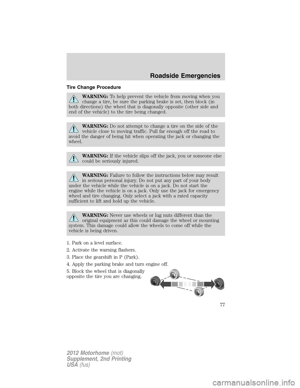
5. Block the wheel that is diagonally
opposite the tire you are changing.
Roadside Emergencies
77
2012 Motorhome(mot)
Supplement, 2nd Printing
USA(fus)
Page 81 of 160

1.Use only a 12–volt supply to start your vehicle.
2. Do not disconnect the battery of the disabled vehicle as this could
damage the vehicle’s electrical system.
3. Park the booster vehicle close to the hood of the disabled vehicle
making sure the two vehiclesdo nottouch. Set the parking brake on
both vehicles and stay clear of the engine cooling fan and other moving
parts.
4. Check all battery terminals and remove any excessive corrosion before
you attach the battery cables. Ensure that vent caps are tight and level.
5. Turn the heater fan on in both vehicles to protect from any electrical
surges. Turn all other accessories off.
Connecting the jumper cables
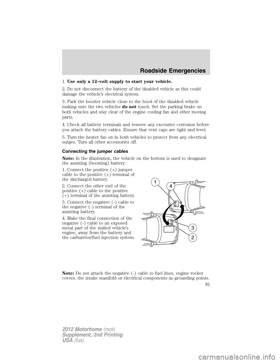
Note:In the illustration, the vehicle on the bottom is used to designate
the assisting (boosting) battery.
1. Connect the positive (+) jumper
cable to the positive (+) terminal of
the discharged battery.
2. Connect the other end of the
positive (+) cable to the positive
(+) terminal of the assisting battery.
3. Connect the negative (-) cable to
the negative (-) terminal of the
assisting battery.
4. Make the final connection of the
negative (-) cable to an exposed
metal part of the stalled vehicle’s
engine, away from the battery and
the carburetor/fuel injection system.
Note:Do not attach the negative (-) cable to fuel lines, engine rocker
covers, the intake manifold or electrical components as grounding points.
+–
+–
2
3
14
Roadside Emergencies
81
2012 Motorhome(mot)
Supplement, 2nd Printing
USA(fus)
Page 82 of 160
WARNING:Do not connect the end of the second cable to the
negative (-) terminal of the battery to be jumped. A spark may
cause an explosion of the gases that surround the battery.
Ensure that the cables are clear of fan blades, belts, moving parts of both
engines, or any fuel delivery system parts.
Jump starting
1. Start the engine of the booster vehicle and run the engine at
moderately increased speed.
2. Start the engine of the disabled vehicle.
3. Once the disabled vehicle has been started, run both engines for an
additional three minutes before disconnecting the jumper cables.
Removing the jumper cables
Remove the jumper cables in the reverse order that they were
connected.
Note:In the illustration, the vehicle on the bottom is used to designate
the assisting (boosting) battery.
Roadside Emergencies
82
2012 Motorhome(mot)
Supplement, 2nd Printing
USA(fus)