Page 1 of 160
Introduction 3
Instrument Cluster 10
Warning lights and chimes 10
Gauges 13
Message center 16
Lights 20
Headlamps 20
Turn signal control 21
Bulb replacement 21
Driver Controls 22
Windshield wiper/washer control 22
Steering wheel adjustment 22
Speed control 23
Tires, Wheels and Loading 25
Tire information 25
Tire inflation 27
Vehicle loading 42
Trailer towing 48
Driving 51
Starting 51
Brakes 54
Transmission operation 58
Roadside Emergencies 64
Getting roadside assistance 64
Hazard flasher control 65
Fuses and relays 66
Changing tires 74
Wheel lug nut torque 79
Jump starting 80
Wrecker towing 83
Table of Contents
1
2012 Motorhome(mot)
Supplement, 2nd Printing
USA(fus)
Page 12 of 160

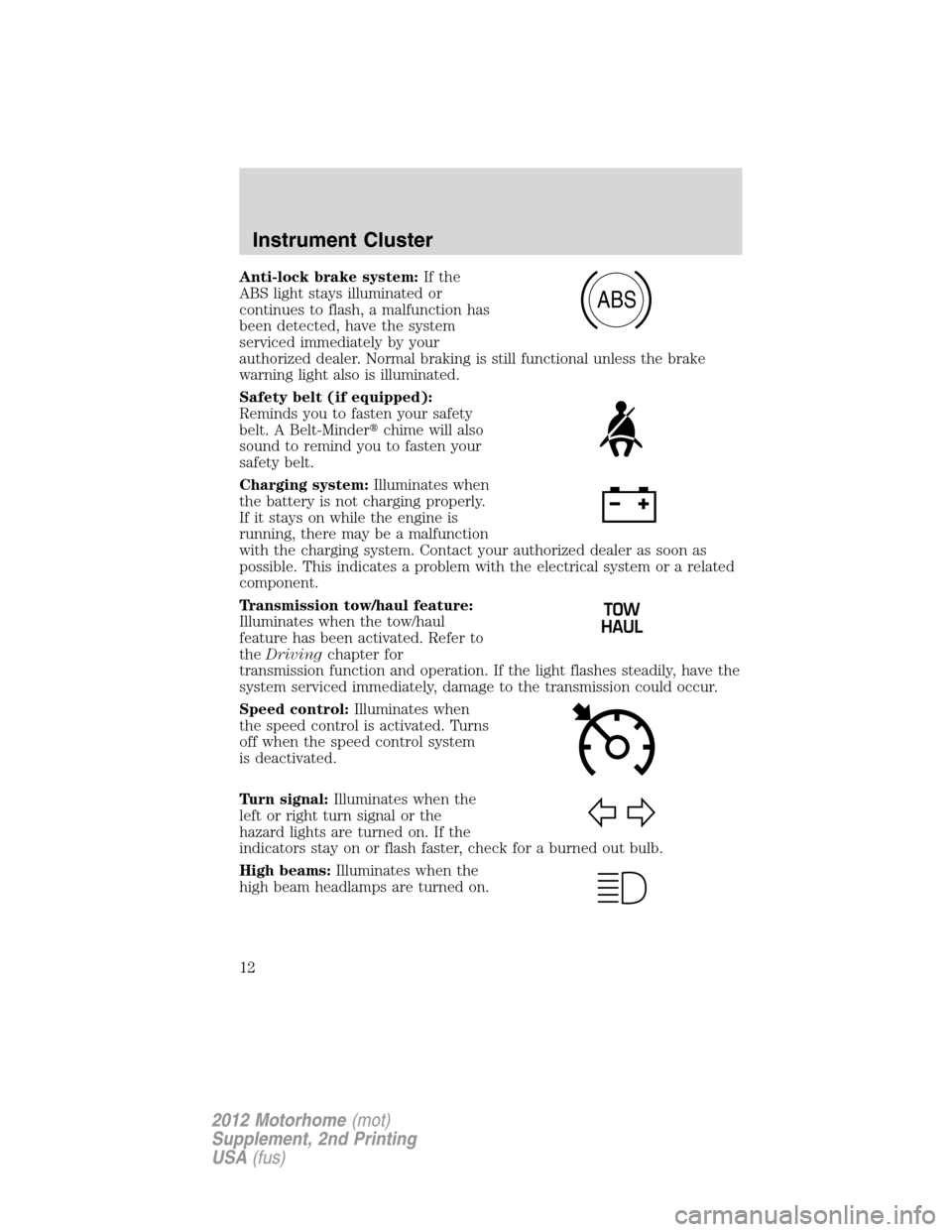
Anti-lock brake system:If the
ABS light stays illuminated or
continues to flash, a malfunction has
been detected, have the system
serviced immediately by your
authorized dealer. Normal braking is still functional unless the brake
warning light also is illuminated.
Safety belt (if equipped):
Reminds you to fasten your safety
belt. A Belt-Minder�chime will also
sound to remind you to fasten your
safety belt.
Charging system:Illuminates when
the battery is not charging properly.
If it stays on while the engine is
running, there may be a malfunction
with the charging system. Contact your authorized dealer as soon as
possible. This indicates a problem with the electrical system or a related
component.
Transmission tow/haul feature:
Illuminates when the tow/haul
feature has been activated. Refer to
theDrivingchapter for
transmission function and operation. If the light flashes steadily, have the
system serviced immediately, damage to the transmission could occur.
Speed control:Illuminates when
the speed control is activated. Turns
off when the speed control system
is deactivated.
Turn signal:Illuminates when the
left or right turn signal or the
hazard lights are turned on. If the
indicators stay on or flash faster, check for a burned out bulb.
High beams:Illuminates when the
high beam headlamps are turned on.
ABS
Instrument Cluster
12
2012 Motorhome(mot)
Supplement, 2nd Printing
USA(fus)
Page 21 of 160
Flash-to-pass
Pull toward you slightly to activate
and release to deactivate.
PANEL DIMMER CONTROL
Use to adjust the brightness of the
instrument panel and all applicable
switches in the vehicle during
headlamp and parking lamp
operation.
•Move the control up or down to
adjust the intensity of the panel
lighting.
•Move the control to the full
upright position, past detent, to turn on the interior lamps.
Note:If the battery is disconnected, discharged, or a new battery is
installed, the dimmer switch requires re-calibration. Rotate the dimmer
switch from the full dim position to the full dome/on position to reset.
This will ensure that your displays are visible under all lighting
conditions.
TURN SIGNAL CONTROL
•Push down to activate the left
turn signal.
•Push up to activate the right turn
signal.
BULB REPLACEMENT
Replacing exterior bulbs
Check the operation of all the bulbs frequently.
Lights
21
2012 Motorhome(mot)
Supplement, 2nd Printing
USA(fus)
Page 49 of 160

5. Install and adjust the tension in the weight distributing bars so that the
height of the front fender is approximately halfway between H1 and H2.
6. Check that the trailer is level. If not level, adjust the ball height
accordingly and repeat Steps 3–6.
WARNING:Do not adjust a weight-distributing hitch to any
position where the rear bumper of the vehicle is higher than it
was before attaching the trailer. Doing so will defeat the function of
the weight-distributing hitch, which may cause unpredictable handling,
and could result in serious personal injury.
Safety chains
Always connect the trailer’s safety chains to the frame or hook retainers
of the vehicle hitch. To connect the trailer’s safety chains, cross the
chains under the trailer tongue and allow slack for turning corners.
If you use a rental trailer, follow the instructions that the rental agency
gives to you.
Do not attach safety chains to the bumper.
Trailer brakes
Electric brakes and manual, automatic or surge-type brakes are safe if
installed properly and adjusted to the manufacturer’s specifications. The
trailer brakes must meet local and Federal regulations.
WARNING:Do not connect a trailer’s hydraulic brake system
directly to your vehicle’s brake system. Your vehicle may not
have enough braking power and your chances of having a collision
greatly increase.
The towing vehicle braking system is rated for operation at the
GVWR, not the GCWR.
Separate functioning brake systems are required for safe control
of towed vehicles and trailers weighing more than 1,500 lb
(680 kg) when loaded.
Trailer lamps
Trailer lamps are required on most towed vehicles. Make sure all running
lights, brake lights, turn signals and hazard lights are working. Contact
your authorized dealer or trailer rental agency for proper instructions
and equipment for hooking-up trailer lamps.
Tires, Wheels and Loading
49
2012 Motorhome(mot)
Supplement, 2nd Printing
USA(fus)
Page 59 of 160

In an emergency, to disable the malfunctioning brake-shift interlock
feature in order to shift the vehicle from P (Park) follow these steps:
WARNING:To prevent vehicle movement when following this
procedure, park on a level surface, ensure parking brake is set,
and block the rear wheels.
1. Apply the parking brake. Turn key to the lock position, and then
remove the key.
2. Disconnect the negative (black) battery cable from the battery.
3. Insert the key and turn to the off position. Shift to N (Neutral).
4. Reconnect the negative (black) battery cable to the battery.
5. Start the vehicle.
See your authorized dealer for service immediately.
WARNING:If your brake lamps are not working properly or if
you have disconnected the vehicle battery cables, the vehicle
brake lamps and hazard flashers may not properly warn traffic of a
vehicle breakdown or approaching danger, which can increase the risk
of serious injury or death. To minimize the risk of serious injury or
death, be aware of your surroundings, use other hazard signaling
devices if available, and move the vehicle to a safe location away from
traffic as soon as possible.
WARNING:Do not drive your vehicle until you verify that the
brake lamps are working.
WARNING:Always set the parking brake fully and make sure
the gearshift is latched in P (Park). Turn the ignition to the lock
position and remove the key whenever you leave your vehicle.
WARNING:If the parking brake is fully released, but the brake
warning lamp remains illuminated, the brakes may not be
working properly. See your authorized dealer.
Driving
59
2012 Motorhome(mot)
Supplement, 2nd Printing
USA(fus)
Page 65 of 160

Vehicles sold in Canada : Using roadside assistance
Complete the roadside assistance identification card and place it in your
wallet for quick reference. In Canada, the card is found in the Warranty
Guide in the glove box.
Canadian Roadside coverage and benefits may differ from the U.S.
coverage. Please refer to your Warranty Guide or visit our website at
www.ford.ca for information on Canadian services and benefits.
Canadian customers who need to obtain roadside information, call
1-800-665-2006 or visit our website at www.ford.ca.
HAZARD FLASHER CONTROL
Note:With extended use, the flasher may run down your battery.
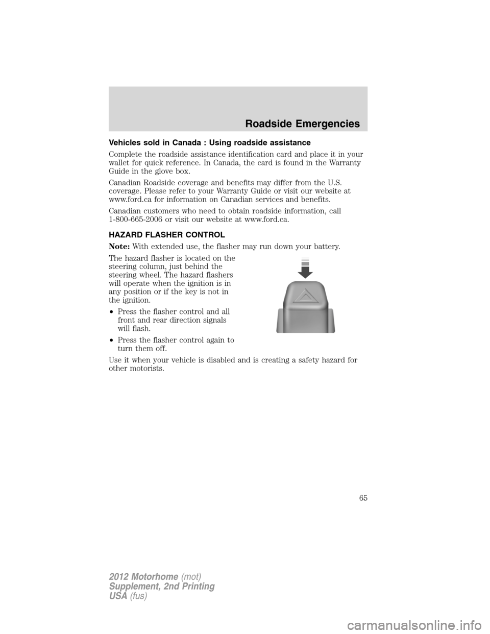
The hazard flasher is located on the
steering column, just behind the
steering wheel. The hazard flashers
will operate when the ignition is in
any position or if the key is not in
the ignition.
•Press the flasher control and all
front and rear direction signals
will flash.
•Press the flasher control again to
turn them off.
Use it when your vehicle is disabled and is creating a safety hazard for
other motorists.
Roadside Emergencies
65
2012 Motorhome(mot)
Supplement, 2nd Printing
USA(fus)
Page 68 of 160
Fuse/Relay
LocationFuse Amp
RatingProtected circuits
7 15A Blower motor relay coil
8 10A Brake lamps feed
9 20A Stoplamps: Vehicle turn/stop
lamps, Body builder rear turn/stop
feeds, Body builder stop lamp
feed
10 10A Instrument cluster memory,
Power brake assist lamp -
Hydromax
11 30A Wiper/washer module, Wiper feed
12 — Not used
13 10A Anti-lock brake system (ABS)
module - Hydromax
14 10A Warning chime module, Power
brake assist module - Hydromax,
Instrument cluster power,
Instrument cluster warning lamps,
Anti-lock brake system (ABS)
module - Hydroboost
15 15A Left turn signal feed
16 20A Body builder battery (+12V) feed
17 5A Body builder radio feed
18 — Not used
19 5A Daytime running lamps (DRL)
relays
20 — Not used
21 15A Right turn signal feed
22 20A Trailer tow turn signals
23 10A Cluster run/accessory
24 — Not used
25 10A Body builder right-hand low beam
headlamp feed
Roadside Emergencies
68
2012 Motorhome(mot)
Supplement, 2nd Printing
USA(fus)
Page 69 of 160
Fuse/Relay
LocationFuse Amp
RatingProtected circuits
26 10A Brake shift interlock actuator
27 — Not used
28 — Not used
29 — Not used
30 — Not used
31 10A Body builder left-hand low beam
headlamp feed
32 — Not used
33 10A Reverse lamps
34 10A Trailer tow reverse lamps, Body
builder reverse gear
35 20A Body builder high beam feed,
High beam indicator, DRL
36 — Not used
37 — Not used
38 10A Body builder run feed
39 — Not used
40 — Not used
41 10A Instrument illumination
42 — Not used
43 — Not used
44 — Not used
Relay 1 — Trailer tow right turn signal
Relay 2 — Trailer tow left turn signal
Relay 3 — Right turn signal
Relay 4 — Left turn signal
Relay 5 — Not used
Relay 6 — DRL, Parking brake
Relay 7 — DRL on/off
Diode 1 — Brake transmission shift interlock
(BTSI)
Diode 2 — BTSI
Roadside Emergencies
69
2012 Motorhome(mot)
Supplement, 2nd Printing
USA(fus)