Page 454 of 652
If both the “Brake Warning Light” and the “Anti-Lock
Brake Warning Light” remain on, the ABS and Electronic
Brake Force Distribution (EBD) systems are not function-
ing. Immediate repair to the ABS system is required.
Consult with your authorized dealer service center as
soon as possible.
ELECTRONIC BRAKE CONTROL SYSTEM
Your vehicle is equipped with an advanced electronic
brake control system that includes the Traction Control
System (TCS), Brake Assist System (BAS) and Electronic
Stability Control (ESC), and Hill Start Assist (HSA).
These systems complement the Anti-Lock Brake System
(ABS) by optimizing the vehicle braking capability dur-
ing emergency braking maneuvers.
Traction Control System (TCS)
The Traction Control System (TCS) monitors the amount
of wheel spin of each of the driven wheels. If wheel spin
is detected, brake pressure is applied to the slippingwheel(s) and engine power is reduced, to provide en-
hanced acceleration and stability. A feature of the TCS
functions similarly to a limited-slip differential, and
controls the wheel spin across a driven axle. If one wheel
on a driven axle is spinning faster than the other, the
system will apply the brake of the spinning wheel. This
will allow more engine torque to be applied to the wheel
that is not spinning. This feature remains active even if
the ESC is in the “Partial Off” mode.
The “ESC Activation/Malfunction Indicator Light” (in
the instrument cluster) will start to flash as soon as the
tires lose traction and the wheels begin to spin. This
indicates that the TCS is active. If the indicator light
flashes during acceleration, ease up on the accelerator
and apply as little throttle as possible. Be sure to adapt
your speed and driving to the prevailing road conditions,
and do not switch off the ESC or TCS.
452 STARTING AND OPERATING
Page 459 of 652
Malfunction Indicator Light” begins to flash during ac-
celeration, ease up on the accelerator and apply as little
throttle as possible. Be sure to adapt your speed and
driving to the prevailing road conditions.
NOTE:
•The “ESC Activation/Malfunction Indicator Light”
and the “ESC OFF Indicator Light” come on momen-
tarily each time the ignition switch is turned ON.
•Each time the ignition is turned ON, the ESC system
will be ON even if it was turned off previously.
•The ESC system will make buzzing or clicking sounds
when it is active. This is normal; the sounds will stop
when ESC becomes inactive following the maneuver
that caused the ESC activation.The “ESC OFF Indicator Light” indicates the
Electronic Stability Control (ESC) is off.
Hill Start Assist (HSA)
The HSA system is designed to assist the driver when
starting a vehicle from a stop on a hill. HSA will maintain
the level of brake pressure the driver applied for a short
period of time after the driver takes their foot off of the
brake pedal. If the driver does not apply the throttle
during this short period of time, the system will release
brake pressure and the vehicle will roll down the hill. The
system will release brake pressure in proportion to the
amount of throttle applied as the vehicle starts to move in
the intended direction of travel.
HSA Activation Criteria
The following criteria must be met in order for HSA to
activate:
•Vehicle must be stopped.
•Vehicle must be on a 6% (approximate) grade or
greater hill.
5
STARTING AND OPERATING 457
Page 460 of 652
•Gear selection matches vehicle uphill direction (i.e.,
vehicle facing uphill is in forward gear; vehicle back-
ing uphill is in REVERSE gear).
HSA will work in REVERSE and all forward gears when
the activation criteria have been met. The system will not
activate if the vehicle is placed in NEUTRAL or PARK.
WARNING!
There may be situations on minor hills (i.e., less than
8%), with a loaded vehicle, or while pulling a trailer,
when the system will not activate and slight rolling
may occur. This could cause a collision with another
vehicle or object. Always remember the driver is
responsible for braking the vehicle.
Disabling/Enabling HSA
If you wish to turn on or off the HSA system, it can be
done using the Customer Programmable Features in the
Electronic Vehicle Information Center (EVIC). Refer to
“Electronic Vehicle Information Center (EVIC)” in “Un-
derstanding Your Instrument Panel” for further informa-
tion.
For vehicles not equipped with the EVIC, perform the
following steps:
NOTE: You must complete Steps 1 through 8 within
90 seconds.
1. Center the steering wheel (front wheels pointing
straight forward).
2. Shift the transmission into NEUTRAL.
3. Apply the parking brake.
4. Start the engine.
458 STARTING AND OPERATING
Page 461 of 652
5. Release the clutch pedal.
6. Rotate the steering wheel one-half turn to the left.
7. Press the “ESC Off” switch (located in the lower
switch bank below the climate controls) four times within
20 seconds. The “ESC Activation/Malfunction Indicator
Light” should turn on and turn off two times.
8. Rotate the steering wheel back to center and then an
additional half-turn to the right.
9. Turn the ignition switch to the OFF position and then
back to the ON position. If the sequence was completed
properly, the “ESC Activation/Malfunction Indicator
Light” will blink several times to confirm HSA is dis-
abled.
10. Repeat these steps if you want to return this feature
to it’s previous setting.Towing With HSA
HSA will provide assistance when starting on a grade
when pulling a trailer.
WARNING!
•If you use a trailer brake controller with your
trailer, your trailer brakes may be activated and
deactivated with the brake switch. If so, when the
brake pedal is released, there may not be enough
brake pressure to hold the vehicle and trailer on a
hill and this could cause a collision with another
vehicle or object behind you. In order to avoid
rolling down the hill while resuming acceleration,
manually activate the trailer brake prior to releas-
ing the brake pedal. Always remember the driver
is responsible for braking the vehicle.(Continued)
5
STARTING AND OPERATING 459
Page 516 of 652
CAUTION!
If the trailer weighs more than 1,000 lbs (454 kg)
loaded, it should have its own brakes and they
should be of adequate capacity. Failure to do this
could lead to accelerated brake lining wear, higher
brake pedal effort, and longer stopping distances.
WARNING!
•Do not connect trailer brakes to your vehicle’s
hydraulic brake lines. It can overload your brake
system and cause it to fail. You might not have
brakes when you need them and could have a
collision.(Continued)
WARNING! (Continued)
•Towing any trailer will increase your stopping
distance. When towing you should allow for addi-
tional space between your vehicle and the vehicle
in front of you. Failure to do so could result in an
collision.
Towing Requirements – Trailer Lights And Wiring
Whenever you pull a trailer, regardless of the trailer size,
stop lights and turn signals on the trailer are required for
motoring safety.
The Trailer Tow Package may include a four-pin or a
seven-pin wiring harness. Use a factory approved trailer
harness and connector.
NOTE:Do not cut or splice wiring into the vehicles
wiring harness.
514 STARTING AND OPERATING
Page 577 of 652
•If frequent engine coolant (antifreeze) additions are
required, or if the level in the coolant recovery bottle
does not drop when the engine cools, the cooling
system should be pressure tested for leaks.
•Maintain engine coolant (antifreeze) concentration at
50% HOAT engine coolant (antifreeze) (minimum)
and distilled water for proper corrosion protection of
your engine, which contains aluminum components.
•Make sure that the radiator and coolant recovery
bottle overflow hoses are not kinked or obstructed.
•Keep the front of the radiator clean. If your vehicle is
equipped with air conditioning, also keep the front of
the condenser clean.
•Do not change the thermostat for Summer or Winter
operation. If replacement is ever necessary, install
ONLY the correct type thermostat. Other designs may
result in unsatisfactory coolant performance, poor gas
mileage, and increased emissions.
Brakes
In order to assure brake system performance, all brake
system components should be inspected periodically.
Refer to the “Maintenance Schedule” for the proper
maintenance intervals.
WARNING!
Riding the brakes can lead to brake failure and
possibly a collision. Driving with your foot resting or
riding on the brake pedal can result in abnormally
high brake temperatures, excessive lining wear, and
possible brake damage. You would not have your full
braking capacity in an emergency.
Master Cylinder – Brake Fluid Level Check
The fluid level in the master cylinder should be checked
when performing underhood services, or immediately if
the “Brake System Warning Light” indicates system
failure.
7
MAINTAINING YOUR VEHICLE 575
Page 591 of 652
CavityCartridge
Fuse Mini-
Fuse Description
M1 — 15 Amp BlueRear Center Brake
Lamp/Brake Switch
M2 — 20 Amp YellowTrailer Lighting, Front
Fog Lamps, Intelli-
gent Battery Sensor
(IBS)
M3 — 20 Amp YellowFront/Rear Axle
Locker, Vacuum
Pump Motor
M4 — 10 Amp RedTrailer Tow
M5 — 25 Amp NaturalInverterCavity
Cartridge
Fuse Mini-
Fuse Description
M6 — 20 Amp YellowPower Outlet #1
(ACC), Rain Sensor,
Cigar Lighter (Instru-
ment Panel or with
Console Rear)
M7 — 20 Amp YellowPower Outlet #2
(BATT/ACC SELECT)
– Center Seat or with
Console Rear
M8 — 20 Amp YellowFront Heated Seat – If
Equipped
M9 — 20 Amp YellowRear Heated Seat – If
Equipped
7
MAINTAINING YOUR VEHICLE 589
Page 594 of 652
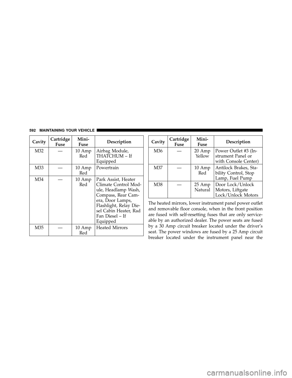
CavityCartridge
Fuse Mini-
Fuse Description
M32 — 10 Amp RedAirbag Module,
THATCHUM – If
Equipped
M33 — 10 Amp RedPowertrain
M34 — 10 Amp RedPark Assist, Heater
Climate Control Mod-
ule, Headlamp Wash,
Compass, Rear Cam-
era, Door Lamps,
Flashlight, Relay Die-
sel Cabin Heater, Rad
Fan Diesel – If
Equipped
M35 — 10 Amp RedHeated MirrorsCavity
Cartridge
Fuse Mini-
Fuse Description
M36 — 20 Amp YellowPower Outlet #3 (In-
strument Panel or
with Console Center)
M37 — 10 Amp RedAntilock Brakes, Sta-
bility Control, Stop
Lamp, Fuel Pump
M38 — 25 Amp NaturalDoor Lock/Unlock
Motors, Liftgate
Lock/Unlock Motors
The heated mirrors, lower instrument panel power outlet
and removable floor console, when in the front position
are fused with self-resetting fuses that are only service-
able by an authorized dealer. The power seats are fused
by a 30 Amp circuit breaker located under the driver’s
seat. The power windows are fused by a 25 Amp circuit
breaker located under the instrument panel near the
592 MAINTAINING YOUR VEHICLE