Page 333 of 557
The button located in the center of the left-hand control
will tune to the next preset station that you have pro-
grammed in the radio preset pushbutton.
CD Player
Pressing the top of the switch once will go to the next
track on the CD. Pressing the bottom of the switch once
will go to the beginning of the current track, or to the
beginning of the previous track if it is within one second
after the current track begins to play.
If you press the switch up or down twice, it plays the
second track; three times, it will play the third, etc.
The center button on the left side rocker switch has no
function for a single-disc CD player. However, when a
multiple-disc CD player is equipped on the vehicle, the
center button will select the next available CD in the
player.
CD/DVD DISC MAINTENANCE
To keep a CD/DVD in good condition, take the following
precautions:
1. Handle the disc by its edge; avoid touching the
surface.
2. If the disc is stained, clean the surface with a soft cloth,
wiping from center to edge.
3. Do not apply paper or tape to the disc; avoid scratch-
ing the disc.
4. Do not use solvents such as benzene, thinner, cleaners,
or anti-static sprays.
5. Store the disc in its case after playing.
6. Do not expose the disc to direct sunlight.
7. Do not store the disc where temperatures may become
too high.
4
UNDERSTANDING YOUR INSTRUMENT PANEL 331
Page 334 of 557
NOTE:If you experience difficulty in playing a particu-
lar disc, it may be damaged (i.e., scratched, reflective
coating removed, a hair, moisture or dew on the disc)
oversized, or have protection encoding. Try a known
good disc before considering disc player service.
RADIO OPERATION AND MOBILE PHONES
Under certain conditions, the mobile phone being on in
your vehicle can cause erratic or noisy performance from
your radio. This condition may be lessened or eliminated
by relocating the mobile phone antenna. This condition is
not harmful to the radio. If your radio performance does
not satisfactorily “clear” by the repositioning of the
antenna, it is recommended that the radio volume be
turned down or off during mobile phone operation when
not using Uconnect™ (if equipped).
CLIMATE CONTROLS
The air conditioning and heating system is designed to
make you comfortable in all types of weather. This
system can be operated through either the Automatic
Climate Controls on the instrument panel or through the
Uconnect Touch™ system display.
When the Uconnect Touch™ system is in different modes
(Radio, Player, Settings, More, etc.) the driver and pas-
senger temperature settings will be indicated at the top of
the display.
332 UNDERSTANDING YOUR INSTRUMENT PANEL
Page 377 of 557
WARNING!
•The Anti-Lock Brake System contains sophisticated
electronic equipment that may be susceptible to
interference caused by improperly installed or high
output radio transmitting equipment. This interfer-
ence can cause possible loss of anti-lock braking
capability. Installation of such equipment should be
performed by qualified professionals.
•Pumping of the anti-lock brakes will diminish
their effectiveness and may lead to an accident.
Pumping makes the stopping distance longer. Just
press firmly on your brake pedal when you need
to slow down or stop.(Continued)
WARNING! (Continued)
•The Anti-Lock Brake System (ABS) cannot prevent
the natural laws of physics from acting on the
vehicle, nor can it increase braking or steering
efficiency beyond that afforded by the condition of
the vehicle brakes and tires or the traction afforded.
•The ABS cannot prevent accidents, including those
resulting from excessive speed in turns, following
another vehicle too closely, or hydroplaning.
•The capabilities of an ABS equipped vehicle must
never be exploited in a reckless or dangerous
manner, which could jeopardize the user’s safety
or the safety of others.
All vehicle wheels and tires must be the same size and
type and tires must be properly inflated to produce
accurate signals for the computer.5
STARTING AND OPERATING 375
Page 413 of 557

If the ignition switch is cycled, this sequence will repeat,
providing the system fault still exists. If the system fault
no longer exists, the TPM Telltale Light will no longer
flash, and the�SERVICE TPM SYSTEM� message will no
longer display, and a pressure value will display in place
of the dashes. A system fault can occur due to any of the
following:
1. Signal interference due to electronic devices or driving
next to facilities emitting the same radio frequencies as
the TPM sensors.
2. Installing aftermarket window tinting that contains
materials that may block radio wave signals.
3. Accumulation of snow or ice around the wheels or
wheel housings. 4. Using tire chains on the vehicle.
5. Using wheels/tires not equipped with TPM sensors.
The EVIC will also display a
�SERVICE TPM SYSTEM�
message for a minimum of five seconds when a system
fault related to an incorrect sensor location fault is
detected. In this case, the �SERVICE TPM SYSTEM�
message is then followed with a graphic display with
pressure values still shown. This indicates that the pres-
sure values are still being received from the TPM sensors
but they may not be located in the correct vehicle
position. The system still needs to be serviced as long as
the �SERVICE TPM SYSTEM� message is displayed.
5
STARTING AND OPERATING 411
Page 444 of 557
1. Set the parking brake, shift the automatic transmission
into PARK and turn the ignition to LOCK.
2. Turn off the heater, radio, and all unnecessary electri-
cal accessories.
3. If using another vehicle to jump-start the battery, park
the vehicle within the jumper cables reach, set the
parking brake and make sure the ignition is OFF.
WARNING!
Do not allow vehicles to touch each other as this
could establish a ground connection and personal
injury could result.
Jump-Starting Procedure
WARNING!
Failure to follow this procedure could result in per-
sonal injury or property damage due to battery ex-
plosion.
CAUTION!
Failure to follow these procedures could result in
damage to the charging system of the booster vehicle
or the discharged vehicle.
442 WHAT TO DO IN EMERGENCIES
Page 488 of 557
Cleaning Headlights
Your vehicle has plastic headlights that are lighter and
less susceptible to stone breakage than glass headlights.
Plastic is not as scratch resistant as glass and therefore
different lens cleaning procedures must be followed.
To minimize the possibility of scratching the lenses and
reducing light output, avoid wiping with a dry cloth. To
remove road dirt, wash with a mild soap solution fol-
lowed by rinsing.
Do not use abrasive cleaning components, solvents, steel
wool or other aggressive material to clean the lenses.
Glass Surfaces
All glass surfaces should be cleaned on a regular basis
with MOPAR�Glass Cleaner or any commercial
household-type glass cleaner. Never use an abrasive type
cleaner. Use caution when cleaning the inside rear win-
dow equipped with electric defrosters or the right rear quarter window equipped with the radio antenna. Do
not use scrapers or other sharp instrument that may
scratch the elements.
When cleaning the rear view mirror, spray cleaner on the
towel or rag that you are using. Do not spray cleaner
directly on the mirror.
Cleaning Plastic Instrument Cluster Lenses
The lenses in front of the instruments in this vehicle are
molded in clear plastic. When cleaning the lenses, care
must be taken to avoid scratching the plastic.
1. Clean with a wet soft rag or micro-fiber towel. A mild
soap solution may be used, but do not use high alcohol
content or abrasive cleaners. If soap is used, wipe clean
with a clean damp rag.
2. Dry with a soft cloth.
486 MAINTAINING YOUR VEHICLE
Page 495 of 557
Cavity Car-tridgeFuse Mini-
Fuse Description
21 — — Fuse — Spare
22 — — Fuse — Spare
23 — 10 Amp RedFuel Door/Diagnostic
Port
24 — 15 Amp BlueRadio Screen
25 — 10 Amp RedTire Pressure Monitor
26 — — Fuse — Spare
27 — 25 Amp NaturalAmplifier
31 — 25 Amp NaturalPower Seats
32 — 15 Amp BlueHVAC Module/ClusterCavity Car-
tridgeFuse Mini-
Fuse Description
33 — 15 Amp BlueIgnition Switch/Wireless
Module
34 — 10 Amp RedSteering Column
Module/Clock
35 — 10 Amp RedBattery Sensor
36 — — Fuse — Spare
37 — 15 Amp BlueRadio
38 — 20 Amp YellowPower Outlet Inside
Arm Rest
40 — — Fuse — Spare
41 — — Fuse — Spare
42 30 Amp Pink — Rear Defrost
7
MAINTAINING YOUR VEHICLE 493
Page 547 of 557
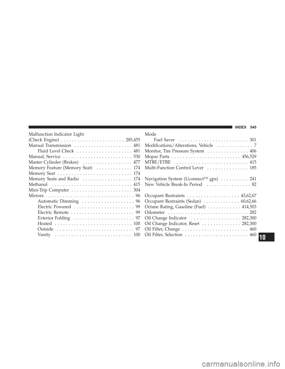
Malfunction Indicator Light
(Check Engine)....................... 285,455
Manual Transmission ..................... 481
Fluid Level Check .................... 481
Manual, Service ......................... 530
Master Cylinder (Brakes) .................. 477
Memory Feature (Memory Seat) ............. 174
Memory Seat ........................... 174
Memory Seats and Radio .................. 174
Methanol ............................. 415
Mini-Trip Computer ...................... 304
Mirrors ................................ 96
Automatic Dimming ................... 96
Electric Powered ...................... 99
Electric Remote ....................... 99
Exterior Folding ...................... 97
Heated ............................ 100
Outside ............................ 97
Vanity ............................ 100 Mode
Fuel Saver ......................... 301
Modifications/Alterations, Vehicle ............. 7
Monitor, Tire Pressure System ............... 406
Mopar Parts ......................... 456,529
MTBE/ETBE ........................... 415
Multi-Function Control Lever ............... 185
Navigation System (Uconnect™ gps) .......... 241
New Vehicle Break-In Period ................ 82
Occupant Restraints ................... 43,62,67
Occupant Restraints (Sedan) .............60,62,66
Octane Rating, Gasoline (Fuel) ............414,503
Odometer ............................. 282
Oil Change Indicator .................. 282,300
Oil Change Indicator, Reset ..............282,300
Oil Filter, Change ........................ 460
Oil Filter, Selection ....................... 460
10
INDEX 545