2012 BMW Z4 SDRIVE35I engine
[x] Cancel search: enginePage 63 of 220

1Button for:▷Selecting the display▷Setting values2Button for:▷Confirming selected display or set val‐
ues▷Calling up computer information 623With the lights switched on: dimming the in‐
strument lighting 714Calling up Check Control 665Checking the engine oil level 1646Initializing the Flat Tire Monitor 76
Resetting the Tire Pressure Monitor 77.7Setting the time 648Setting the date 659Viewing service requirement display 6510Setting formats and units of measure, re‐
setting to factory settings 6311Changing settings▷Confirmation signals when locking and
unlocking the vehicle 24▷Response during unlocking proce‐
dure 22▷Automatic locking 26▷Headlamp courtesy delay feature 68▷Daytime running lights 69▷Triple turn signal activation 50▷Seat memory 39Exiting displays
The external temperature reading and the time
reappear when you press button 2 or if you make
no entries within approx. 15 seconds. If required,
complete the current setting first.Formats and units of measure
You can set formats and units of measure.1.Switch on the ignition, refer to page 45.2.Lightly push button 1 in the turn indicator
lever up or down repeatedly until the symbolSeite 63DisplaysControls63
Online Edition for Part no. 01 40 2 609 184 - 09 11 500
Page 66 of 220

Possible displays1Button for selecting functions2Service requirements3Engine oil4Roadworthiness test5Front brake pads6Rear brake pads7Brake fluidThe sequence of displayed service items may
vary. The data for the next service appointment
is shown first.
Check Control
The concept
The Check Control monitors vehicle functions
and alerts you to any malfunctions in the sys‐
tems monitored.
Such Check Control messages involve indicator
or warning lamps in the instrument cluster and,
in some circumstances, an acoustic signal.Indicator/warning lamps
The indicator and warning lamps can light up in
a variety of combinations and colors.
Seite 66ControlsDisplays66
Online Edition for Part no. 01 40 2 609 184 - 09 11 500
Page 68 of 220

LampsVehicle equipment
This chapter describes all series equipment as
well as country-specific and special equipment
offered for this model series.Therefore, it also
describes equipment that may not be found in
your vehicle, for instance due to the selected
special equipment or the country version. This
also applies to safety-related functions and sys‐
tems.
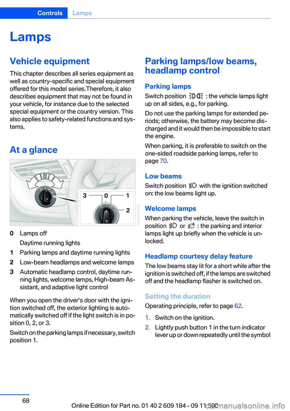
At a glance0Lamps off
Daytime running lights1Parking lamps and daytime running lights2Low-beam headlamps and welcome lamps3Automatic headlamp control, daytime run‐
ning lights, welcome lamps, High-beam As‐
sistant, and adaptive light control
When you open the driver's door with the igni‐
tion switched off, the exterior lighting is auto‐
matically switched off if the light switch is in po‐
sition 0, 2, or 3.
Switch on the parking lamps if necessary, switch
position 1.
Parking lamps/low beams,
headlamp control
Parking lamps
Switch position
: the vehicle lamps light
up on all sides, e.g., for parking.
Do not use the parking lamps for extended pe‐
riods; otherwise, the battery may become dis‐
charged and it would then be impossible to start
the engine.
When parking, it is preferable to switch on the
one-sided roadside parking lamps, refer to
page 70.
Low beams
Switch position
with the ignition switched
on: the low beams light up.
Welcome lamps
When parking the vehicle, leave the switch in
position
or : the parking and interior
lamps light up briefly when the vehicle is un‐
locked.
Headlamp courtesy delay feature
The low beams stay lit for a short while after the
ignition is switched off, if the lamps are switched
off and the headlamp flasher is switched on.
Setting the duration
Operating principle, refer to page 62.
1.Switch on the ignition.2.Lightly push button 1 in the turn indicator
lever up or down repeatedly until the symbolSeite 68ControlsLamps68
Online Edition for Part no. 01 40 2 609 184 - 09 11 500
Page 70 of 220

4.Lightly push button 1 in the turn indicator
lever up or down repeatedly until the symbol
appears in the display.5.Press button 2.6.Use button 1 to select one of the following:▷ Daytime running lights are acti‐
vated.▷ Daytime running lights are de‐
activated.7.Press button 2.
The setting is stored for the remote control cur‐
rently in use.
Adaptive light control
The concept
Adaptive light control is a variable headlamp
control system that enables dynamic illumina‐
tion of the road surface.
Depending on the steering angle and other pa‐
rameters, the light from the headlamp follows
the course of the road.
Controls
Activating
Switch position
with the ignition switched
on.
Auxiliary function:
To avoid blinding oncoming traffic, the adaptive
light control directs light towards the front pas‐
senger side when the vehicle is at a standstill.
Malfunction
Adaptive light control is malfunctioning or has
failed. Have the system checked as soon as pos‐
sible.
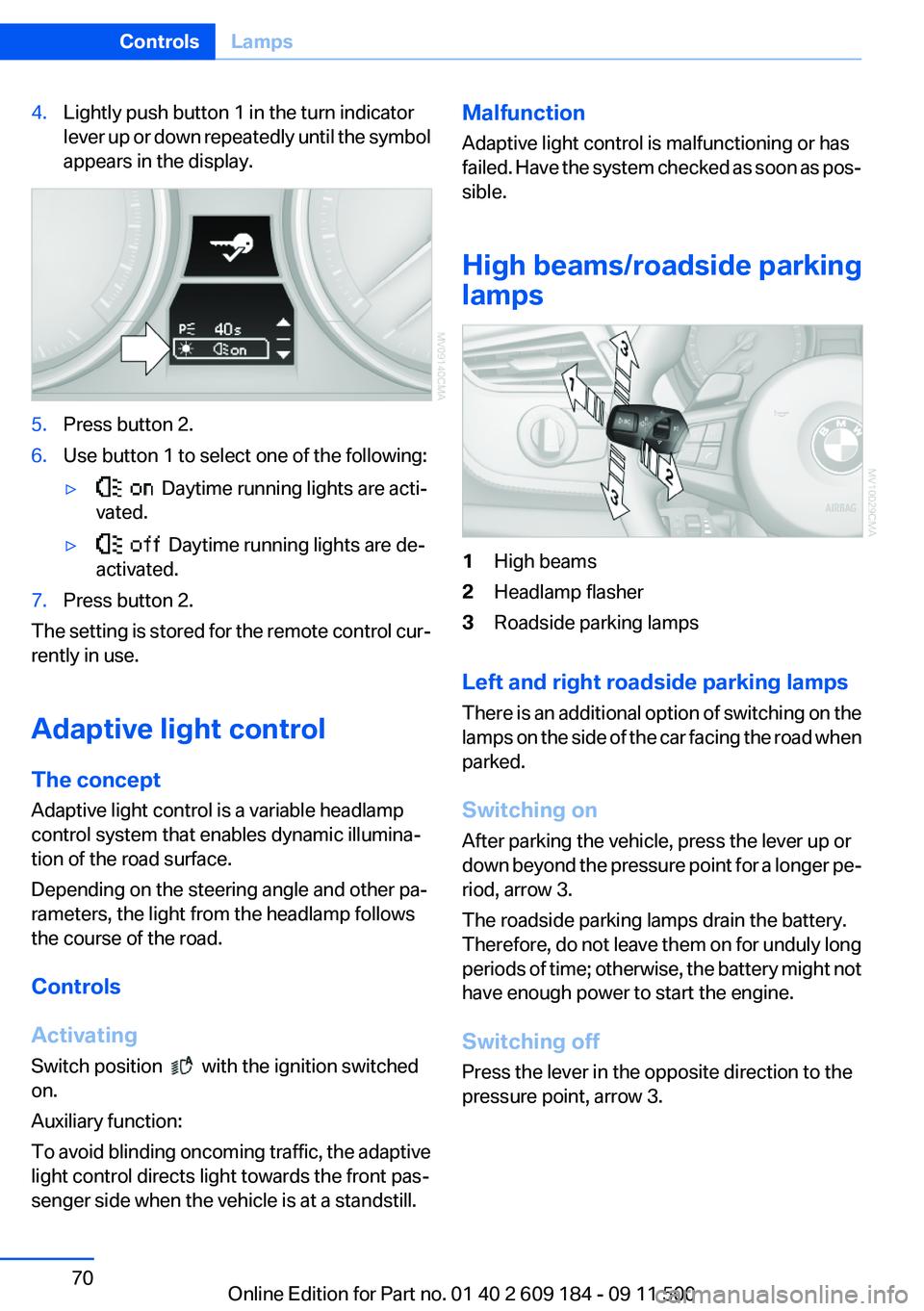
High beams/roadside parking
lamps1High beams2Headlamp flasher3Roadside parking lamps
Left and right roadside parking lamps
There is an additional option of switching on the
lamps on the side of the car facing the road when
parked.
Switching on
After parking the vehicle, press the lever up or
down beyond the pressure point for a longer pe‐
riod, arrow 3.
The roadside parking lamps drain the battery.
Therefore, do not leave them on for unduly long
periods of time; otherwise, the battery might not
have enough power to start the engine.
Switching off
Press the lever in the opposite direction to the
pressure point, arrow 3.
Seite 70ControlsLamps70
Online Edition for Part no. 01 40 2 609 184 - 09 11 500
Page 76 of 220

▷When driving on a snowy or slippery road
surface.▷Sporty driving style: slip in the drive wheels,
high lateral acceleration.▷When driving with snow chains.
Initialization
The initialization process adopts the set inflation
tire pressures as reference values for the detec‐
tion of a flat tire. Initialization is started by con‐
firming the inflation pressures.
Do not initialize the system when driving with
snow chains.
Operating principle, refer to page 62.
1.Start the engine immediately before pulling
away, but do not drive off yet.2.Lightly push button 1 in the turn indicator
lever up or down repeatedly until the appro‐
priate symbol appears in the display, ac‐
companied by the word "RESET".3.Press button 2 to confirm your choice of the
Flat Tire Monitor.4.Press button 2 for approx. 5 seconds until
the display appears:5.Drive away.
Initialization is completed while the car is on
the move without providing feedback.
Indication of a flat tire
The warning lamps come on in yellow
and red. In addition, a signal sounds.
There is a flat tire or a major loss in tire
inflation pressure.
1.Reduce your speed and stop cautiously.
Avoid sudden braking and steering maneu‐
vers.2.Check whether the vehicle is fitted with reg‐
ular tires or run-flat tires.
Run-flat tires, refer to page 161, are labeled
with a circular symbol containing the letters
RSC marked on the tire sidewall.
Do not continue driving without run-flat
tires
Do not continue driving if the vehicle is not
equipped with run-flat tires; continued driving
may result in serious accidents.◀
When a flat tire is indicated, DSC Dynamic Sta‐
bility Control is switched on if necessary.
Actions in the event of a flat tire
Normal tires
1.Identify the damaged tire.
Do this by checking the air pressure in all
four tires.Seite 76ControlsSafety76
Online Edition for Part no. 01 40 2 609 184 - 09 11 500
Page 78 of 220

in spite of the fact that the tire is filled to the cor‐
rect inflation pressure.
The system is deactivated and is unable to de‐
tect flat tires if a wheel not equipped with TPM
electronics has been mounted, e.g., a compact
wheel, or if TPM is experiencing temporary in‐
terference from other systems or devices that
use the same frequency.
Resetting the system
Reset the system after each correction of the
tire inflation pressure and after every tire or
wheel change.
Operating principle, refer to page 62.1.Start the engine, but do not start driving.2.Lightly push button 1 in the turn indicator
lever up or down repeatedly until the appro‐
priate symbol appears in the display, ac‐
companied by the word "RESET".3.Press button 2 to confirm your choice of the
Tire Pressure Monitor.
The following display appears:4.Press button 2 for approx. 5 seconds until
the small warning lamp lights up yellow and
the following display appears:5.Drive away.
After driving a few minutes, the set inflation
pressures in the tires are accepted as the
target values to be monitored. The system
reset is completed during your drive, and
can be interrupted at any time. When driving
resumes, the reset is continued automati‐
cally. The indicator lamp goes out after the
system reset is completed.
Low tire pressure message
The warning lamps come on in yellow
and red. In addition, a signal sounds.
▷There is a flat tire or a major loss in
tire inflation pressure.▷The system was not reset after a wheel
change and thus issues warnings based on
the inflation pressures initialized last.1.Reduce your speed and stop cautiously.
Avoid sudden braking and steering maneu‐
vers.2.Check whether the vehicle is fitted with reg‐
ular tires or run-flat tires.
Run-flat tires , refer to page 160, are labeled
with a circular symbol containing the letters
RSC marked on the tire sidewall.Seite 78ControlsSafety78
Online Edition for Part no. 01 40 2 609 184 - 09 11 500
Page 81 of 220

Driving stability control systemsVehicle equipment
This chapter describes all series equipment as
well as country-specific and special equipment
offered for this model series.Therefore, it also
describes equipment that may not be found in
your vehicle, for instance due to the selected
special equipment or the country version. This
also applies to safety-related functions and sys‐
tems.
Antilock Brake System ABS
ABS prevents locking of the wheels during brak‐
ing.
The vehicle remains steerable even during full
brake applications, thus increasing active
safety.
ABS is operational every time you start the en‐
gine.
Electronic brake-force
distribution
The system controls the brake pressure in the
rear wheels to ensure stable braking behavior.
Dynamic Brake Control DBC
When you apply the brakes rapidly, this system
automatically produces the maximum braking
force boost. It thus helps to achieve the shortest
possible braking distance during full braking.
This system utilizes all of the benefits provided
by ABS.
Do not reduce the pressure on the brake pedal
for the duration of the full braking.Dynamic Stability Control
DSC
The concept
DSC prevents traction loss in the driving wheels
when driving away and accelerating.
DSC also recognizes unstable vehicle condi‐
tions, such as fishtailing or nose-diving. Subject
to physical limits, DSC helps to keep the vehicle
on a steady course by reducing engine speed
and by applying brakes to the individual wheels.
Adjust your driving style to the situation
An appropriate driving style is always the
responsibility of the driver.
The laws of physics cannot be repealed, even
with DSC.
Therefore, do not reduce the additional safety
margin by driving in a risky manner.◀
Activating/deactivating DSC
DSC can be deactivated/activated via the DSC
OFF program of the Dynamic Driving Control,
refer to page 82.
For better control The DSC indicator lamp flashes: DSC is
controlling the drive forces and brake
forces.
The DSC indicator lamp lights up: DSC has
failed.Seite 81Driving stability control systemsControls81
Online Edition for Part no. 01 40 2 609 184 - 09 11 500
Page 85 of 220

Driving comfortVehicle equipment
This chapter describes all series equipment as
well as country-specific and special equipment
offered for this model series.Therefore, it also
describes equipment that may not be found in
your vehicle, for instance due to the selected
special equipment or the country version. This
also applies to safety-related functions and sys‐
tems.
Cruise control
The concept
Cruise control is available for use at speeds of
approx. 20 mph/30 km/h and higher. The car
then stores and maintains the speed that you
specify using the lever on the steering column.
In order to maintain the specified speed, the
system brakes the vehicle when the engine
braking effect is insufficient on downhill gradi‐
ents.
Do not use cruise control
Do not use the system if unfavorable con‐
ditions make it impossible to drive at a constant
speed, for instance:▷On curvy roads.▷In heavy traffic.▷On slippery roads, in fog, snow or rain, or on
a loose road surface.
Otherwise, you could lose control of the vehicle
and cause an accident.◀
Manual transmission
You can shift gears while cruise control is acti‐
vated. An indicator lamp notifies you that you
should shift gears when you drive for an ex‐
tended period at very high or very low engine
speeds, or the system is deactivated.
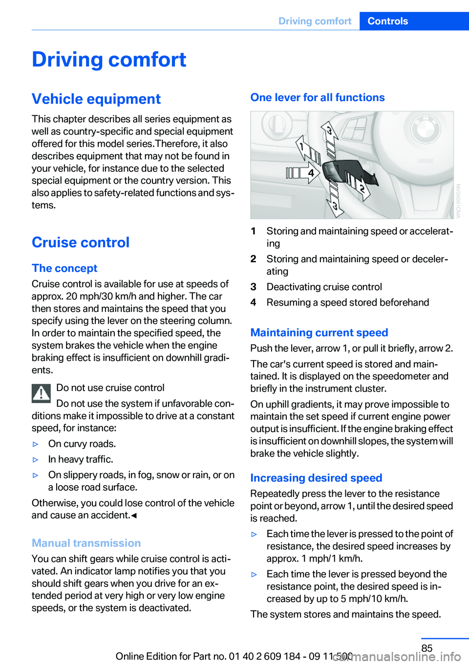
One lever for all functions1Storing and maintaining speed or accelerat‐
ing2Storing and maintaining speed or deceler‐
ating3Deactivating cruise control4Resuming a speed stored beforehand
Maintaining current speed
Push the lever, arrow 1, or pull it briefly, arrow 2.
The car's current speed is stored and main‐
tained. It is displayed on the speedometer and
briefly in the instrument cluster.
On uphill gradients, it may prove impossible to
maintain the set speed if current engine power
output is insufficient. If the engine braking effect
is insufficient on downhill slopes, the system will
brake the vehicle slightly.
Increasing desired speed
Repeatedly press the lever to the resistance
point or beyond, arrow 1, until the desired speed
is reached.
▷Each time the lever is pressed to the point of
resistance, the desired speed increases by
approx. 1 mph/1 km/h.▷Each time the lever is pressed beyond the
resistance point, the desired speed is in‐
creased by up to 5 mph/10 km/h.
The system stores and maintains the speed.
Seite 85Driving comfortControls85
Online Edition for Part no. 01 40 2 609 184 - 09 11 500