2012 BMW 650I ECU
[x] Cancel search: ECUPage 82 of 282

3.
Open "Options".
4. "Last Service Request"
Check Control
The concept
The Check Control system monitors functions
in
the vehicle and notifies you of malfunctions in
the monitored systems.
A Check Control message is displayed as a
combination of indicator or warning lamps and
text messages in the instrument cluster and in
the Head-up Display*.
In addition, an acoustic signal may be output and
a text message may appear on the Control Dis‐
play.
Indicator/warning lamps The indicator and warning lamps can light up in
a variety of combinations and colors.
Several of the lamps are checked for proper
functioning and light up temporarily when the
engine is started or the ignition is switched on.
Text messages
Text
messages in combination with a symbol in
the instrument cluster explain a Check Control
message and the meaning of the indicator and
warning lamps.
Supplementary text messages
Addition information, such as on the cause of a
fault or the required action, can be called up via
Check Control. The supplementary text of ur‐
gent messages is displayed automatically. It is shown on the Control Display.
Symbols
Depending on the Check Control message, the
following functions can be selected.
▷
"Owner's Manual"
Display additional information about the
Check Control message in the integrated
owner's manual.
▷ "Service request"
Contact the service partner.
▷ "Roadside Assistance"
Contact Roadside Assistance.
Hiding Check Control messages Press the computer button on the turn signal
lever.
▷
Some Check Control messages are dis‐
played
continuously and are not cleared un‐
til the malfunction is eliminated. If several
malfunctions occur at once, the messages
are displayed consecutively.
These messages can be hidden for approx.
8 seconds. After this time, they are dis‐
played again automatically.
▷ Other Check Control messages are hidden
automatically after approx. 20 seconds.
They
are stored and can be displayed again
later.
Displaying stored Check Control
messages
1. "Vehicle Info"
2. "Vehicle status"
Seite 82
82 Online Edition for Part no. 01 40 2 606 521 - 03 11 490
Displays
Page 91 of 282
Rollover protection system
The concept
The
rollover protection system is activated dur‐
ing an accident or a critical driving situation,
when there is extreme tilt with respect to the
longitudinal axis or when there is loss of ground
contact. The safety frames located behind the
rear headrests extend within fractions of a sec‐
ond.
In addition to the rollover bracket integrated in
the front windshield frame, the rollover protec‐
tion system guarantees the required head clear‐
ance of all vehicle occupants.
Maintaining movement space
Always keep the movement space of the
rollover protection system clear. Otherwise,
there may be damage or injuries when the roll‐
over protection system is triggered.◀
In less severe accidents, the secured safety belt
and, depending on the severity of the accident,
the belt tensioner and airbag restraint system
provide protection.
Triggered rollover protection system
After deployment or damage
After deployment of the rollover protec‐
tion system or in the event of damage, have the
system checked and replaced.
Have this work performed only by your service
center; otherwise, it cannot be ensured that this
safety feature will function properly.◀
Do not move convertible top
When the rollover protection system is ex‐
tended, do not move the convertible top. Oth‐
erwise, damages or injuries may result.◀
If the rollover protection system was not placed
under any stress after an automatic triggering, it
can be pushed back by hand, e.g. to close the
convertible top. Three people are necessary for
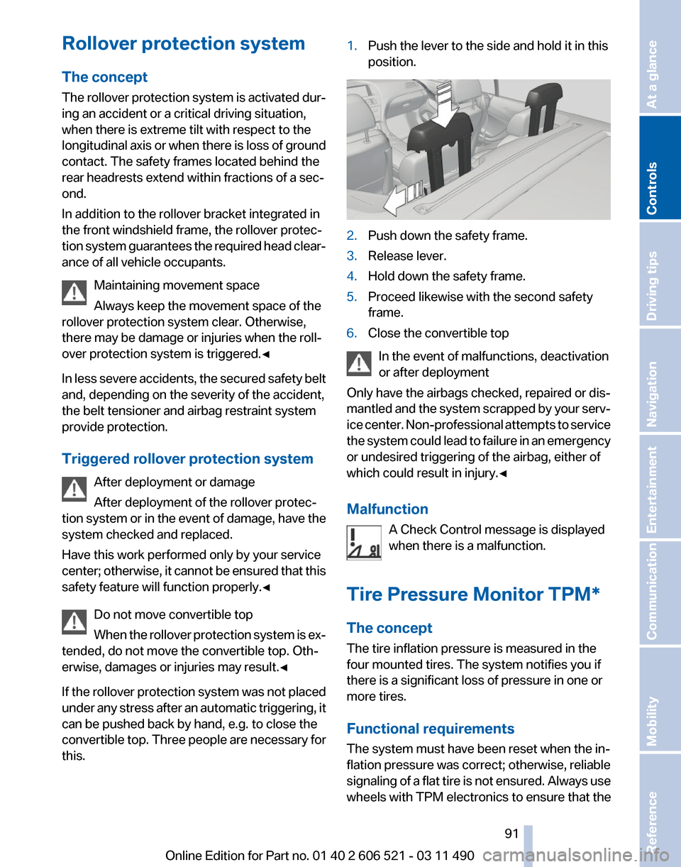
this. 1.
Push the lever to the side and hold it in this
position. 2.
Push down the safety frame.
3. Release lever.
4. Hold down the safety frame.
5. Proceed likewise with the second safety
frame.
6. Close the convertible top
In the event of malfunctions, deactivation
or after deployment
Only have the airbags checked, repaired or dis‐
mantled
and the system scrapped by your serv‐
ice center. Non-professional attempts to service
the system could lead to failure in an emergency
or undesired triggering of the airbag, either of
which could result in injury.◀
Malfunction
A Check Control message is displayed
when there is a malfunction.
Tire Pressure Monitor TPM*
The concept
The tire inflation pressure is measured in the
four mounted tires. The system notifies you if
there is a significant loss of pressure in one or
more tires.
Functional requirements
The system must have been reset when the in‐
flation pressure was correct; otherwise, reliable
signaling of a flat tire is not ensured. Always use
wheels with TPM electronics to ensure that the Seite 91
91Online Edition for Part no. 01 40 2 606 521 - 03 11 490
Reference Mobility Communication Entertainment Navigation Driving tips
Controls At a glance
Page 120 of 282
is moving from the right or left to the central area.
Display in the Head-up Display
*
The warning is simultaneously dis‐
played in the Head-up Display and in the
Control Display. The displayed symbol
can vary with the people detected. For people
located in the central area, the distance to the
person is indicated by the size of the symbol.
System limits
Basic limits
System operation is limited in situations such as
the following:
▷ On steep hills, in steep depressions or in
tight curves.
▷ When the camera is dirty or the protective
glass is damaged.
▷ In heavy fog, rain or snowfall.
▷ At very high external temperatures.
Limits of pedestrian detection
Animals are not detected by the pedestrian de‐
tection
function, even if they are clearly visible in
the image.
Limited pedestrian detection:
▷ When people are fully or partially covered,
especially when their heads are covered.
▷ When people are not in an upright position,
e.g., when lying down.
▷ Cyclists on unconventional bicycles (e.g.,
recumbent bicycles).
▷ After physical damage to the system, e.g.,
after an accident. Activation/deactivation
Press the button.
Display
Settings via iDrive
With Night Vision switched on:
1. Activate Night Vision with pedestrian detec‐
tion.
2. Press the controller.
3. Open the desired menu item.
▷ "Brightness"
▷ "Contrast"
▷ "Pedestrian detection"
The settings are stored for the remote control
currently in use.
Camera Rain, dirt, snow, or ice can impair camera oper‐
ation.
The camera is automatically heated when the
external temperatures are low.
The camera is automatically cleaned together
with the headlamps. Seite 120
120 Online Edition for Part no. 01 40 2 606 521 - 03 11 490
Driving comfort
Page 128 of 282
Interior equipment
Integrated universal remote
control*
The concept
This system can replace up to three different
hand-held transmitters for various types of re‐
mote-controlled equipment, such as garage
doors or lighting systems.
The hand-held transmitter signal can be pro‐
grammed on one of the three memory buttons.
The
corresponding device can then be operated
using the programmed memory button.
The LED indicates that a signal is being trans‐
mitted.
When selling the vehicle, delete the stored pro‐
grams for security reasons.
During programming
During programming and before activat‐
ing a device using the universal remote control,
ensure that there are no people, animals, or ob‐
jects in the range of movement of the remote-
controlled device; otherwise, there is a risk of
injury or damage.
Also follow the safety instructions of the hand-
held transmitter.◀
Compatibility
If this symbol is printed on the packaging
or in the instructions of the hand-held
transmitter, the remote-controlled de‐
vice is generally compatible with the universal
remote control.
If you have any questions, please contact:
▷ Your service center.
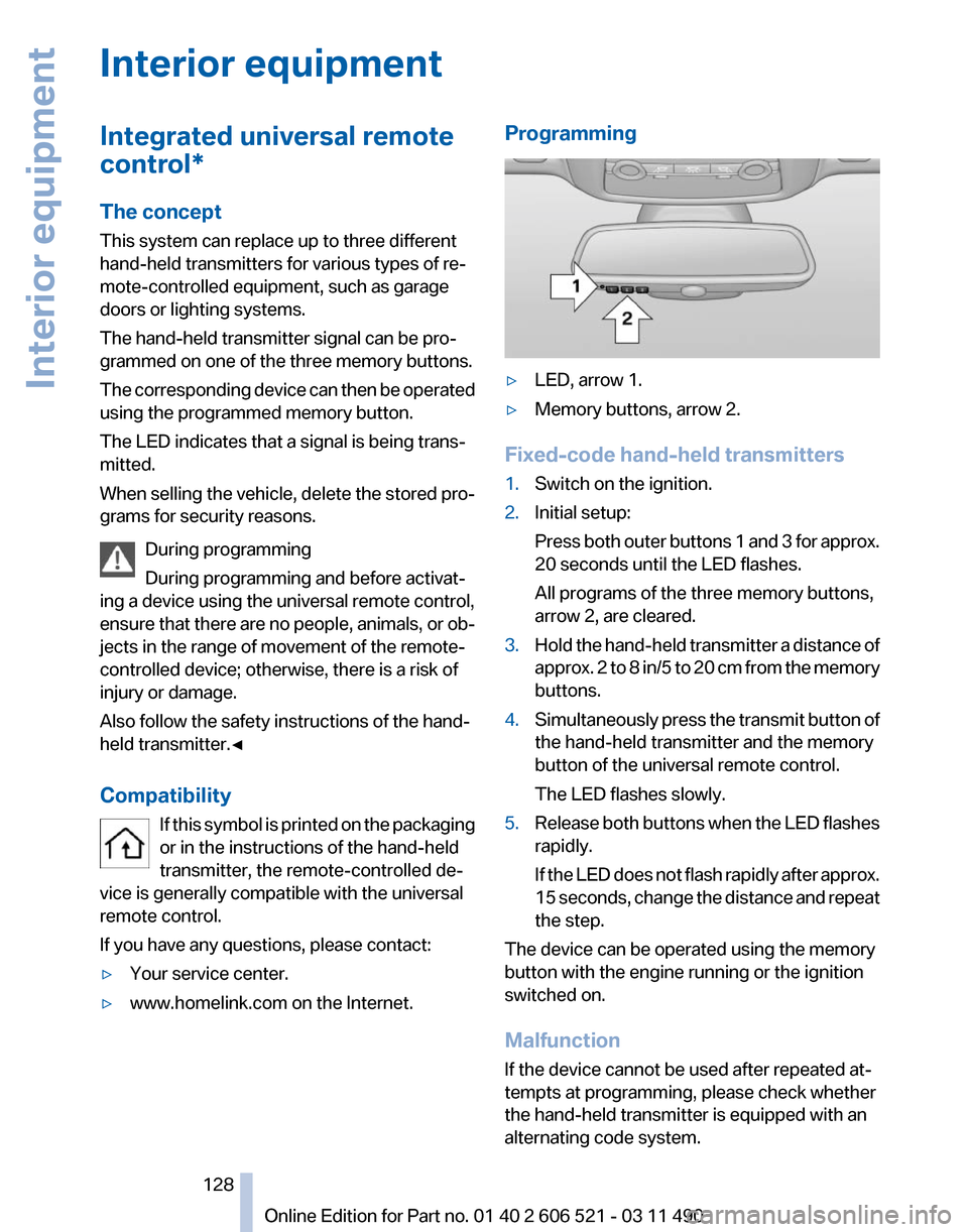
▷ www.homelink.com on the Internet. Programming
▷
LED, arrow 1.
▷ Memory buttons, arrow 2.
Fixed-code hand-held transmitters
1. Switch on the ignition.
2. Initial setup:
Press
both outer buttons 1 and 3 for approx.
20 seconds until the LED flashes.
All programs of the three memory buttons,
arrow 2, are cleared.
3. Hold the hand-held transmitter a distance of
approx.
2 to 8 in/5 to 20 cm from the memory
buttons.
4. Simultaneously press the transmit button of
the hand-held transmitter and the memory
button of the universal remote control.
The LED flashes slowly.
5. Release both buttons when the LED flashes
rapidly.
If
the LED does not flash rapidly after approx.
15 seconds, change the distance and repeat
the step.
The device can be operated using the memory
button with the engine running or the ignition
switched on.
Malfunction
If the device cannot be used after repeated at‐
tempts at programming, please check whether
the hand-held transmitter is equipped with an
alternating code system.
Seite 128
128 Online Edition for Part no. 01 40 2 606 521 - 03 11 490
Interior equipment
Page 131 of 282
Ski bag*
Capacity
The ski bag makes it possible to transport two
pairs of skis up to a length of 6 ft/2.10 m.
Preparing and loading the ski bag
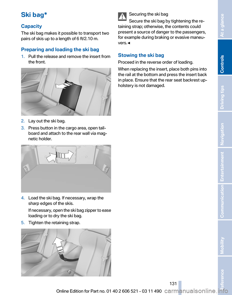
1.
Pull the release and remove the insert from
the front. 2.
Lay out the ski bag.
3. Press button in the cargo area, open tail‐
board and attach to the rear wall via mag‐
netic holder. 4.
Load the ski bag. If necessary, wrap the
sharp edges of the skis.
If
necessary, open the ski bag zipper to ease
loading or to dry the ski bag.
5. Tighten the retaining strap. Securing the ski bag
Secure the ski bag by tightening the re‐
taining strap; otherwise, the contents could
present a source of danger to the passengers,
for example during braking or evasive maneu‐
vers.◀
Stowing the ski bag
Proceed in the reverse order of loading.
When replacing the insert, place both pins into
the rail at the bottom and press the insert back
in place. Ensure that the rear seat backrest up‐
holstery is not damaged. Seite 131
131Online Edition for Part no. 01 40 2 606 521 - 03 11 490
Reference Mobility Communication Entertainment Navigation Driving tips
Controls At a glance
Page 134 of 282
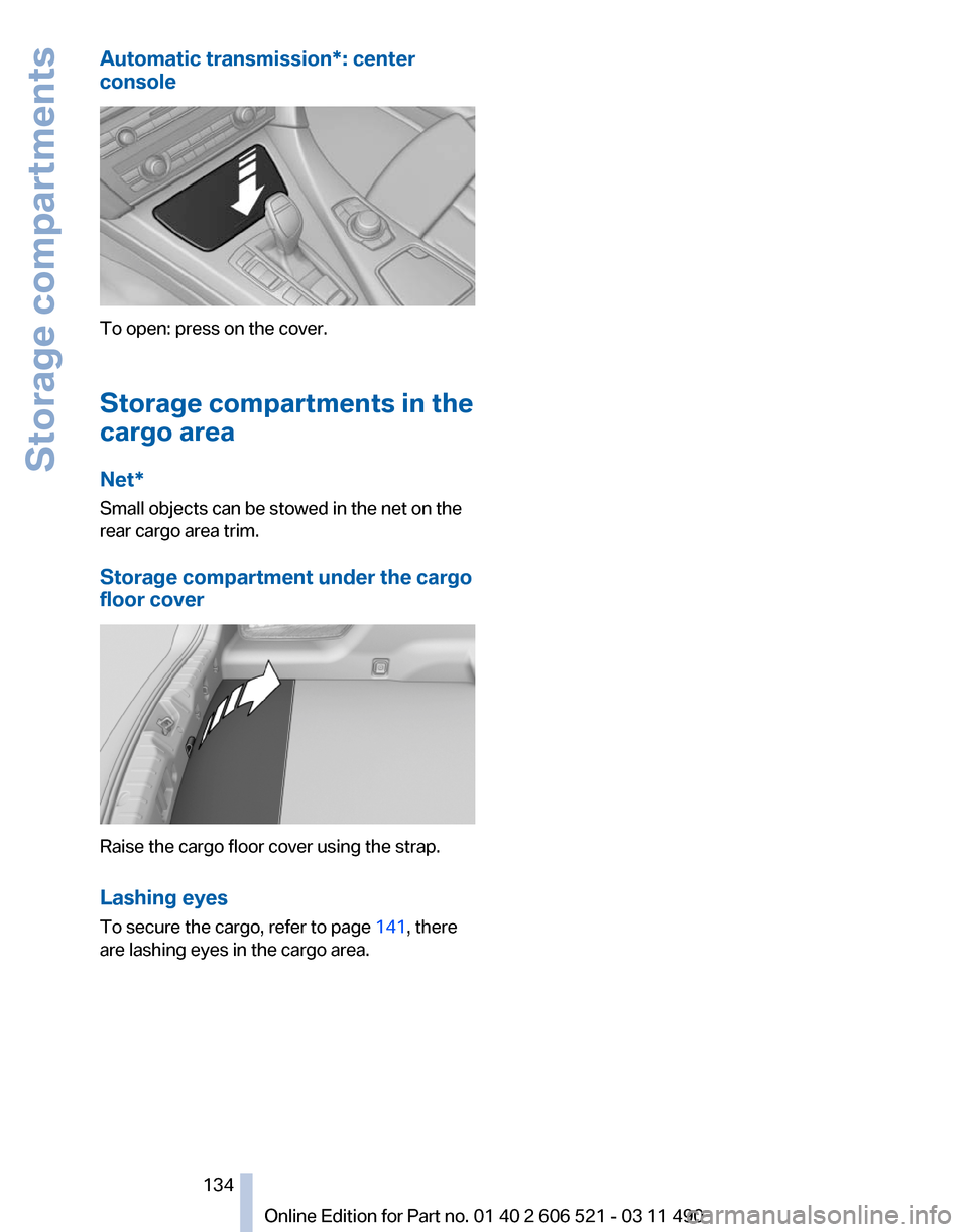
Automatic transmission*: center
console
To open: press on the cover.
Storage compartments in the
cargo area
Net*
Small objects can be stowed in the net on the
rear cargo area trim.
Storage compartment under the cargo
floor cover
Raise the cargo floor cover using the strap.
Lashing eyes
To secure the cargo, refer to page
141, there
are lashing eyes in the cargo area.
Seite 134
134 Online Edition for Part no. 01 40 2 606 521 - 03 11 490Storage compartments
Page 139 of 282

Climate control windshield*
The marked area is not covered with heat re‐
flective coating.
Use this area for garage door openers, devices
for electronic toll collection, etc.
Mobile communication devices in the
vehicle
Mobile communication devices in the ve‐
hicle
It
is advised that you do not use mobile commu‐
nication devices, e.g., mobile phones, inside the
vehicle without connecting them directly to the
external antenna. Otherwise, the vehicle elec‐
tronics and mobile communication devices can
interfere with each other. In addition, there is no
assurance that the radiation generated during
transmission will be discharged from the vehicle
interior.◀
Hydroplaning
On wet or slushy roads, a wedge of water can
form between the tires and road surface.
This phenomenon is referred to as hydroplan‐
ing. It is characterized by a partial or complete
loss of contact between the tires and the road
surface, ultimately undermining your ability to
steer and brake the vehicle.
Hydroplaning
When driving on wet or slushy roads, re‐
duce your speed to prevent hydroplaning.◀ Driving through water
Drive though calm water only if it is not deeper
than 9.8 inches/25 cm and at this height, no
faster
than walking speed, up to 6 mph/10 km/h.
Adhere to water depth and speed limita‐
tions
Do not exceed this water depth and walking
speed; otherwise, the vehicle's engine, the elec‐
trical systems and the transmission may be
damaged.◀
Braking safely
Your vehicle is equipped with ABS as a standard
feature.
Applying the brakes fully is the most effective
way of braking in situations when this is neces‐
sary.
The vehicle maintains steering responsiveness.
You can still avoid any obstacles with a minimum
of steering effort.
Pulsation of the brake pedal and sounds from
the hydraulic circuits indicate that ABS is in its
active mode.
Objects in the area around the pedals
No objects in the area around the pedals
Keep floor mats, carpets, and any other
objects out of the area of motion of the pedals;
otherwise, the function of the pedals could be
impeded while driving
Do not place additional floor mats over existing
mats or other objects.
Only use floor mats that have been approved for
the vehicle and can be properly fixed in place.
Ensure that the floor mats are securely fastened
again after they were removed for cleaning, for
example.◀
Driving in wet conditions
When roads are wet or there is heavy rain, briefly
exert gentle pressure on the brake pedal every
few miles.
Ensure that this action does not endanger other
road users. Seite 139
139Online Edition for Part no. 01 40 2 606 521 - 03 11 490
Reference Mobility Communication Entertainment Navigation
Driving tips Controls At a glance
Page 141 of 282
4.
The resulting figure equals the available
amount
of cargo and luggage load capacity.
For example, if the YYY amount equals
1,000 lbs and there will be four 150 lbs pas‐
sengers in your vehicle, the amount of avail‐
able cargo and luggage load capacity is
400 lbs: 1,000 lbs minus 600 lbs = 400 lbs.
5. Determine the combined weight of luggage
and
cargo being loaded on the vehicle. That
weight may not safely exceed the available
cargo and luggage load capacity calculated
in Step 4.
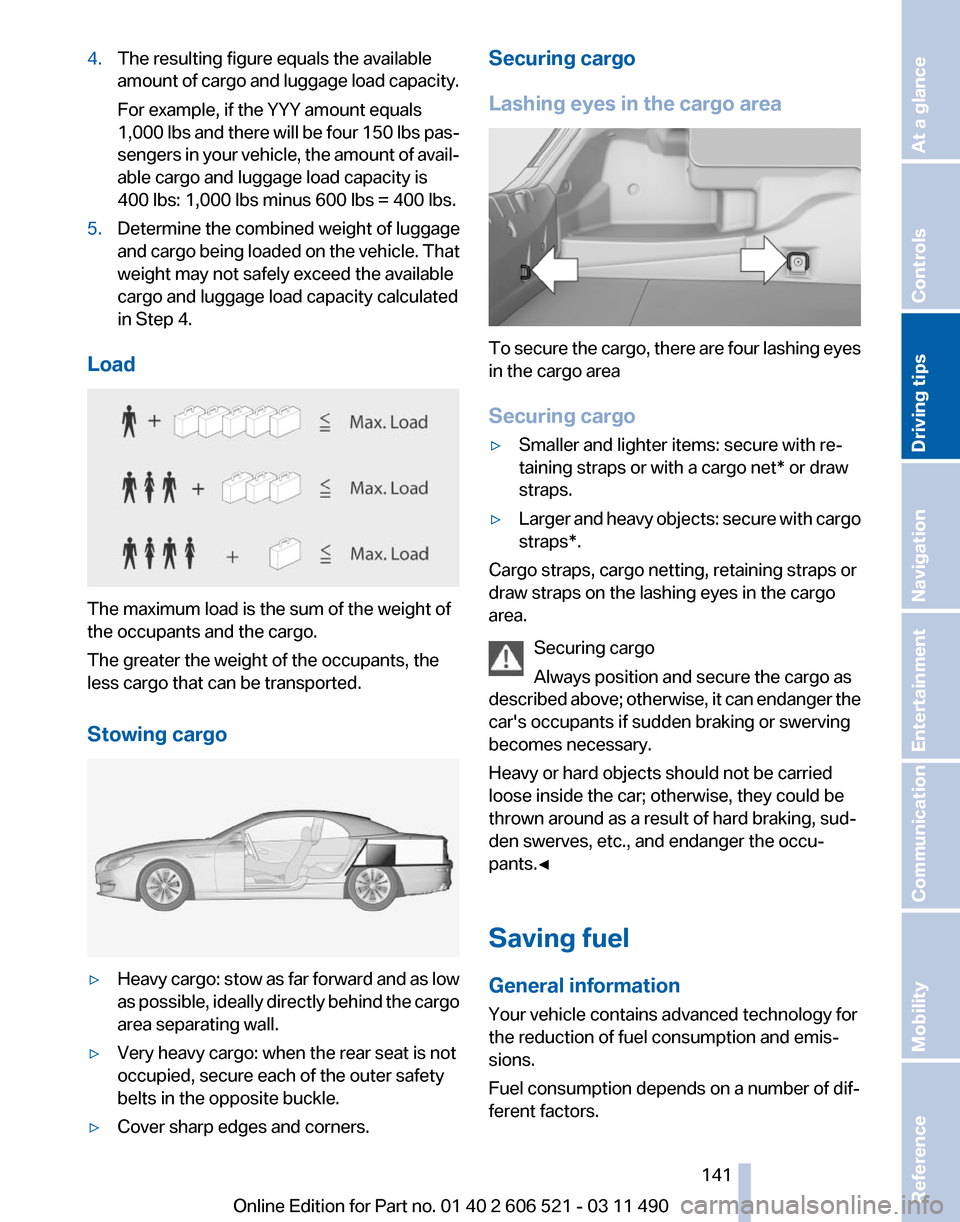
Load The maximum load is the sum of the weight of
the occupants and the cargo.
The greater the weight of the occupants, the
less cargo that can be transported.
Stowing cargo
▷
Heavy cargo: stow as far forward and as low
as
possible, ideally directly behind the cargo
area separating wall.
▷ Very heavy cargo: when the rear seat is not
occupied, secure each of the outer safety
belts in the opposite buckle.
▷ Cover sharp edges and corners. Securing cargo
Lashing eyes in the cargo area
To secure the cargo, there are four lashing eyes
in the cargo area
Securing cargo
▷
Smaller and lighter items: secure with re‐
taining straps or with a
cargo net* or draw
straps.
▷ Larger and heavy objects: secure with cargo
straps*.
Cargo straps, cargo netting, retaining straps or
draw straps on the lashing eyes in the cargo
area.
Securing cargo
Always position and secure the cargo as
described
above; otherwise, it can endanger the
car's occupants if sudden braking or swerving
becomes necessary.
Heavy or hard objects should not be carried
loose inside the car; otherwise, they could be
thrown around as a result of hard braking, sud‐
den swerves, etc., and endanger the occu‐
pants.◀
Saving fuel
General information
Your vehicle contains advanced technology for
the reduction of fuel consumption and emis‐
sions.
Fuel consumption depends on a number of dif‐
ferent factors. Seite 141
141Online Edition for Part no. 01 40 2 606 521 - 03 11 490
Reference Mobility Communication Entertainment Navigation
Driving tips Controls At a glance