Page 89 of 112

PERIODIC MAINTENANCE AND ADJUSTMENT
6-33
6
EAU47311
Replacing the fuses The main fuse, the fuel injection system
fuse, and the fuse boxes, which contain
the fuses for the individual circuits, are
located under the rider seat. (See page
3-25.)
If a fuse is blown, replace it as follows.
1. Turn the key to “OFF” and turn off
the electrical circuit in question.
2. Remove the blown fuse, and then
install a new fuse of the specified
amperage. WARNING! Do not
use a fuse of a higher amperage
rating than recommended toavoid causing extensive dam-
age to the electrical system and
possibly a fire.
[EWA15131]
3. Turn the key to “ON” and turn on
the electrical circuit in question to
check if the device operates.
4. If the fuse immediately blows
again, have a Yamaha dealer
check the electrical system.
1. Main fuse
2. Fuse box
3. Fuel injection system spare fuse
4. Fuel injection system fuse
3
4
12
1. Ignition fuse
2. Signaling system fuse
3. Electronic throttle valve fuse
4. Backup fuse (for clock and immobilizer sys-
tem)
5. Right radiator fan fuse
6. Left radiator fan fuse
7. Spare fuse
8. Steering damper fuse
9. Turn signal light fuse
10.Headlight fuse
3
4
2
1
5
6
7
8 9 107
Specified fuses:
Main fuse:
50.0 A
Headlight fuse:
20.0 A
Signaling system fuse:
7.5 A
Ignition fuse:
15.0 A
Radiator fan fuse:
15.0 A × 2
Turn signal light fuse:
7.5 A
Steering damper fuse:
7.5 A
Fuel injection system fuse:
15.0 A
Backup fuse:
7.5 A
Electronic throttle valve fuse:
7.5 A
U14BE2E0.book Page 33 Friday, June 18, 2010 8:47 AM
Page 90 of 112

PERIODIC MAINTENANCE AND ADJUSTMENT
6-34
6
EAU39012
Replacing a headlight bulb This model is equipped with quartz bulb
headlights. If a headlight bulb burns
out, replace it as follows.NOTICE
ECA10650
Take care not to damage the follow-
ing parts:�
Headlight bulb
Do not touch the glass part of
the headlight bulb to keep it free
from oil, otherwise the transpar-
ency of the glass, the luminosity
of the bulb, and the bulb life will
be adversely affected. Thor-
oughly clean off any dirt and fin-
gerprints on the headlight bulb
using a cloth moistened with al-
cohol or thinner.
�
Headlight lens
Do not affix any type of tinted
film or stickers to the headlight
lens.
Do not use a headlight bulb of a
wattage higher than specified.
1. Remove the headlight bulb cover
by turning it counterclockwise.
2. Disconnect the headlight coupler.3. Unhook the headlight bulb holder,
and then remove the burnt-out
bulb.
4. Place a new headlight bulb into po-
sition, and then secure it with the
bulb holder.1. Do not touch the glass part of the bulb.
1. Headlight bulb cover
1
1. Headlight coupler
1. Headlight bulb
2. Headlight bulb holder
1
12
U14BE2E0.book Page 34 Friday, June 18, 2010 8:47 AM
Page 91 of 112
PERIODIC MAINTENANCE AND ADJUSTMENT
6-35
6 5. Connect the headlight coupler.
6. Install the headlight bulb cover by
turning it clockwise.
7. Have a Yamaha dealer adjust the
headlight beam if necessary.
EAU24181
Tail/brake light This model is equipped with an LED-
type tail/brake light.
If the tail/brake light does not come on,
have a Yamaha dealer check it.
EAU24204
Replacing a turn signal light
bulb 1. Remove the turn signal light lens
by removing the screw.
2. Remove the burnt-out bulb by
pushing it in and turning it counter-
clockwise.
3. Insert a new bulb into the socket,
push it in, and then turn it clock-
wise until it stops.
4. Install the lens by installing the
screw. NOTICE: Do not over-
tighten the screw, otherwise the
lens may break.
[ECA11191]
1. Screw
1
U14BE2E0.book Page 35 Friday, June 18, 2010 8:47 AM
Page 92 of 112

PERIODIC MAINTENANCE AND ADJUSTMENT
6-36
6
EAU24313
Replacing the license plate
light bulb 1. Remove the license plate light unit
by removing the screws.
2. Remove the license plate light bulb
socket (together with the bulb) by
pulling it out.3. Remove the burnt-out bulb by pull-
ing it out.
4. Insert a new bulb into the socket.
5. Install the socket (together with the
bulb) by pushing it in.
6. Install the license plate light unit by
installing the screws.
EAU32833
Replacing an auxiliary light
bulb This model is equipped with two auxil-
iary lights. If an auxiliary light bulb burns
out, replace it as follows.
1. Remove panel A (if replacing the
left auxiliary light bulb) or panel B
(if replacing the right auxiliary light
bulb). (See page 6-8.)
2. Remove the auxiliary light bulb
socket (together with the bulb) by
pulling it out.
3. Remove the burnt-out bulb by pull-
ing it out.
1. License plate light unit
2. Screw
1
2
1. License plate light bulb
2. License plate light bulb socket
12
1. Auxiliary light bulb socket
1
U14BE2E0.book Page 36 Friday, June 18, 2010 8:47 AM
Page 93 of 112
 by push-
ing it in.
6. Install the panel.
EAU2435")
PERIODIC MAINTENANCE AND ADJUSTMENT
6-37
6 4. Insert a new bulb into the socket.
5. Install the auxiliary light bulb sock-
et (together with the bulb) by push-
ing it in.
6. Install the panel.
EAU24350
Supporting the motorcycle Since this model is not equipped with a
centerstand, follow these precautions
when removing the front and rear
wheel or performing other maintenance
requiring the motorcycle to stand up-
right. Check that the motorcycle is in a
stable and level position before starting
any maintenance. A strong wooden
box can be placed under the engine for
added stability.
To service the front wheel
1. Stabilize the rear of the motorcycle
by using a motorcycle stand or, if
an additional motorcycle stand is
not available, by placing a jack un-
der the frame in front of the rear
wheel.
2. Raise the front wheel off the
ground by using a motorcycle
stand.
To service the rear wheel
Raise the rear wheel off the ground by
using a motorcycle stand or, if a motor-
cycle stand is not available, by placinga jack either under each side of the
frame in front of the rear wheel or under
each side of the swingarm.
1. Auxiliary light bulb
1
U14BE2E0.book Page 37 Friday, June 18, 2010 8:47 AM
Page 94 of 112

PERIODIC MAINTENANCE AND ADJUSTMENT
6-38
6
EAU24360
Front wheel
EAU33923
To remove the front wheel
WARNING
EWA10821
To avoid injury, securely support the
vehicle so there is no danger of it
falling over.1. Loosen the front wheel axle pinch
bolts, the axle bolt, and then the
brake caliper bolts.
2. Lift the front wheel off the ground
according to the procedure on
page 6-37.3. Remove the brake hose holder on
each side by removing the bolt and
nut.
4. Remove the brake caliper on each
side by removing the bolts.
5. Remove the axle bolt, push the
wheel axle out from the left side,
and then remove the wheel.
NOTICE: Do not apply the brake
after the brake calipers have
been removed, otherwise the
brake pads will be forced shut.
[ECA11051]EAU33934
To install the front wheel
1. Lift the wheel up between the fork
legs.
2. Insert the wheel axle.
3. Install the axle bolt, and then lower
the front wheel so that it is on the
ground, and then put the sidestand
down.
4. Install the brake calipers by install-
ing the bolts, and then tightening
them to the specified torque.TIPMake sure that there is enough space
between the brake pads before install-
ing the brake calipers onto the brake
discs.
1. Front wheel axle pinch bolt11
1. Brake hose holder
2. Bolt and nut
3. Brake caliper bolt
4. Brake caliper
5. Axle bolt
1
2
3
4 5
1. Wheel axle
1
U14BE2E0.book Page 38 Friday, June 18, 2010 8:47 AM
Page 95 of 112

PERIODIC MAINTENANCE AND ADJUSTMENT
6-39
6 5. Install the brake hose holders by
installing the bolts and nuts.
6. Tighten the axle bolt to the speci-
fied torque.
TIPWhile tightening the axle bolt, hold the
wheel axle with a 19-mm hexagon
wrench to keep it from turning.7. Tighten wheel axle pinch bolt B,
then pinch bolt A to the specified
torque.8. Retighten pinch bolt B to the spec-
ified torque.
9. Tap the outer side of the right fork
leg with a rubber mallet to align it
with the end of the wheel axle.
10. Tighten wheel axle pinch bolt D,
then pinch bolt C to the specified
torque.
11. Retighten pinch bolt D to the spec-
ified torque.12. While applying the front brake,
push down hard on the handlebar
several times to check for proper
fork operation.Tightening torque:
Brake caliper bolt:
35 Nm (3.5 m·kgf, 25 ft·lbf)
Tightening torque:
Axle bolt:
91 Nm (9.1 m·kgf, 66 ft·lbf)
1. Front wheel axle pinch bolt A
2. Front wheel axle pinch bolt B
3. Front wheel axle pinch bolt C
4. Front wheel axle pinch bolt D
Tightening torque:
Wheel axle pinch bolt:
21 Nm (2.1 m·kgf, 15 ft·lbf)41
3
2
Tightening torque:
Wheel axle pinch bolt:
21 Nm (2.1 m·kgf, 15 ft·lbf)
U14BE2E0.book Page 39 Friday, June 18, 2010 8:47 AM
Page 96 of 112

PERIODIC MAINTENANCE AND ADJUSTMENT
6-40
6
EAU25080
Rear wheel
EAU25314
To remove the rear wheel
WARNING
EWA10821
To avoid injury, securely support the
vehicle so there is no danger of it
falling over.1. Loosen the axle nut.
2. Lift the rear wheel off the ground
according to the procedure on
page 6-37.
3. Remove the axle nut.4. Fully loosen the locknut on each
side of the swingarm.
5. Turn the drive chain slack adjust-
ing bolts fully in direction (a) and
push the wheel forward.
6. Remove the drive chain from the
rear sprocket.
TIP�
If the drive chain is difficult to re-
move, remove the wheel axle first,
and then lift the wheel upward
enough to remove the drive chain
from the rear sprocket.
�
The drive chain cannot be disas-
sembled.
7. While supporting the brake caliper
bracket, pull the wheel axle out,
and then remove the wheel.
NOTICE: Do not apply the brake
after the wheel has been re-
moved together with the brake
disc, otherwise the brake pads
will be forced shut.
[ECA11071]EAU25663
To install the rear wheel
1. Install the wheel and the brake cal-
iper bracket by inserting the wheel
axle from the left-hand side.TIP�
Be sure to insert the retainer on the
brake caliper bracket into the slot
in the swingarm.
�
Make sure that there is enough
space between the brake pads be-
fore installing the wheel.
1. Axle nut
2. Brake caliper bracket
3. Brake caliper
4. Locknut
5. Drive chain slack adjusting bolt12
3
5
4(a)
1. Wheel axle
1
U14BE2E0.book Page 40 Friday, June 18, 2010 8:47 AM
 1
1 2
2 3
3 4
4 5
5 6
6 7
7 8
8 9
9 10
10 11
11 12
12 13
13 14
14 15
15 16
16 17
17 18
18 19
19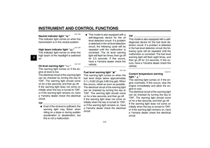 20
20 21
21 22
22 23
23 24
24 25
25 26
26 27
27 28
28 29
29 30
30 31
31 32
32 33
33 34
34 35
35 36
36 37
37 38
38 39
39 40
40 41
41 42
42 43
43 44
44 45
45 46
46 47
47 48
48 49
49 50
50 51
51 52
52 53
53 54
54 55
55 56
56 57
57 58
58 59
59 60
60 61
61 62
62 63
63 64
64 65
65 66
66 67
67 68
68 69
69 70
70 71
71 72
72 73
73 74
74 75
75 76
76 77
77 78
78 79
79 80
80 81
81 82
82 83
83 84
84 85
85 86
86 87
87 88
88 89
89 90
90 91
91 92
92 93
93 94
94 95
95 96
96 97
97 98
98 99
99 100
100 101
101 102
102 103
103 104
104 105
105 106
106 107
107 108
108 109
109 110
110 111
111