Page 83 of 166
4-23
KICK SHAFT AND SHIFT SHAFT
KICK SHAFT AND SHIFT SHAFT
REMOVING THE PRIMARY DRIVE GEAR
Order Part name Q'ty Remarks
Drain the transmission oil. Refer to "CHANGING THE TRANSMISSION
OIL" section in the CHAPTER 3.
Clutch cable Disconnect at engine side.
Bolt (brake pedal) Shift the brake pedal downward.
Radiator hose 4 Disconnect at water pump side.
Bolt (push rod)Refer to "CYLINDER HEAD, CYLINDER
AND PISTON" section.
1 Kickstarter crank 1
2 Crankcase cover (right) 1
3 Bolt (Primary drive gear) 1 Only loosening. Refer to removal section.
4 Primary driven gear 1 Refer to "CLUTCH" section.
5 Primary drive gear 1
Page 86 of 166

4-26
KICK SHAFT AND SHIFT SHAFT
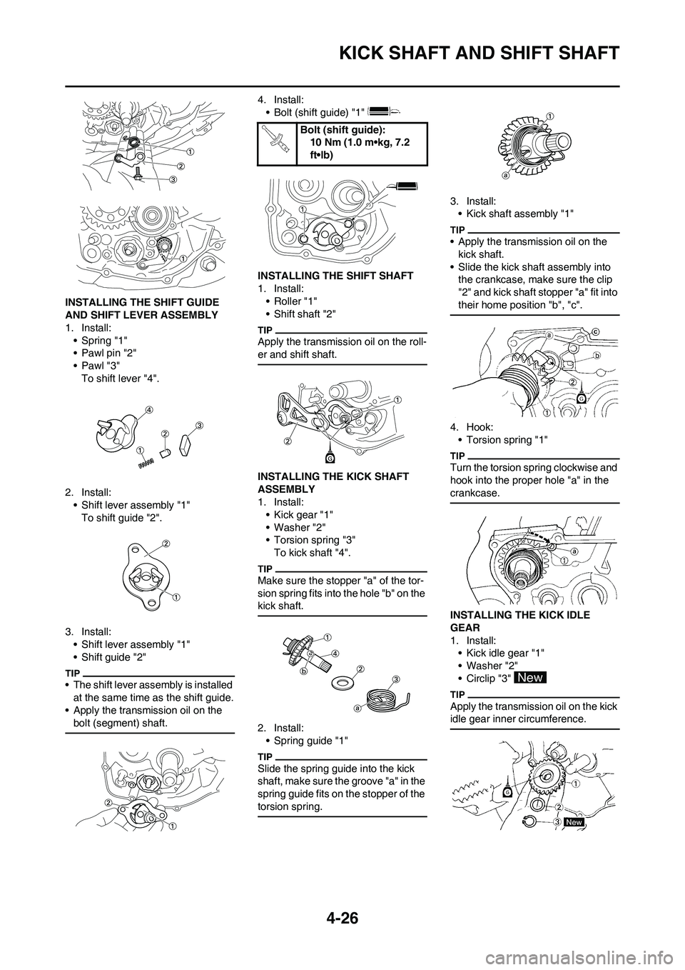
INSTALLING THE SHIFT GUIDE
AND SHIFT LEVER ASSEMBLY
1. Install:
• Spring "1"
• Pawl pin "2"
•Pawl "3"
To shift lever "4".
2. Install:
• Shift lever assembly "1"
To shift guide "2".
3. Install:
• Shift lever assembly "1"
• Shift guide "2"
• The shift lever assembly is installed
at the same time as the shift guide.
• Apply the transmission oil on the
bolt (segment) shaft.
4. Install:
• Bolt (shift guide) "1"
INSTALLING THE SHIFT SHAFT
1. Install:
• Roller "1"
• Shift shaft "2"
Apply the transmission oil on the roll-
er and shift shaft.
INSTALLING THE KICK SHAFT
ASSEMBLY
1. Install:
• Kick gear "1"
• Washer "2"
• Torsion spring "3"
To kick shaft "4".
Make sure the stopper "a" of the tor-
sion spring fits into the hole "b" on the
kick shaft.
2. Install:
• Spring guide "1"
Slide the spring guide into the kick
shaft, make sure the groove "a" in the
spring guide fits on the stopper of the
torsion spring.
3. Install:
• Kick shaft assembly "1"
• Apply the transmission oil on the
kick shaft.
• Slide the kick shaft assembly into
the crankcase, make sure the clip
"2" and kick shaft stopper "a" fit into
their home position "b", "c".
4. Hook:
• Torsion spring "1"
Turn the torsion spring clockwise and
hook into the proper hole "a" in the
crankcase.
INSTALLING THE KICK IDLE
GEAR
1. Install:
• Kick idle gear "1"
• Washer "2"
• Circlip "3"
Apply the transmission oil on the kick
idle gear inner circumference.
Bolt (shift guide):
10 Nm (1.0 m•kg, 7.2
ft•lb)
Page 89 of 166
4-29
YPVS GOVERNOR
REMOVING THE GOVERNOR
1. Remove:
• Dowel pin "1"
While compressing the spring, re-
move the dowel pin.
CHECKING THE GOVERNOR
GROOVE
1. Inspect:
• Washer "1"
•Collar "2"
Wear/Damage→Replace.
CHECKING THE BEARING
1. Inspect:
• Thrust bearing "1"
• Washer "2"
Wear/Damage→Replace.
INSTALLING THE GOVERNOR
1. Install:
• Governor gear "1"
• Compression spring "2"
• Plate "3"
• Washer "4"
• Thrust bearing "5"
•Collar "6"
• Retainer weight "7"
To governor shaft "8".
Apply the lithium soap base grease
on the thrust bearing.
2. Install:
• Ball "1"
• Retainer "2"
To governor shaft "3".
Apply the transmission oil on the re-
tainer and ball.
3. Install:
• Dowel pin "1"
• While compressing the spring, in-
stall the dowel pin.
• Make sure the dowel pin fits into the
groove "a" in the retainer.
4. Install:
• Governor assembly "1"
Align the groove "a" in the governor
with the fork "b" and set the governor
in the crankcase cover.
Page 90 of 166
4-30
WATER PUMP
WATER PUMP
DISASSEMBLING THE WATER PUMP
Order Part name Q'ty Remarks
Crankcase cover (right)Refer to "KICK SHAFT AND SHIFT SHAFT"
section.
1 Water pump housing cover 1
2 Impeller shaft gear 1
3 Dowel pin 1
4 Plain washer 1
5 Impeller shaft assembly 1
6 Bearing 1 Refer to removal section.
7 Oil seal 2 Refer to removal section.
Page 91 of 166

4-31
WATER PUMP
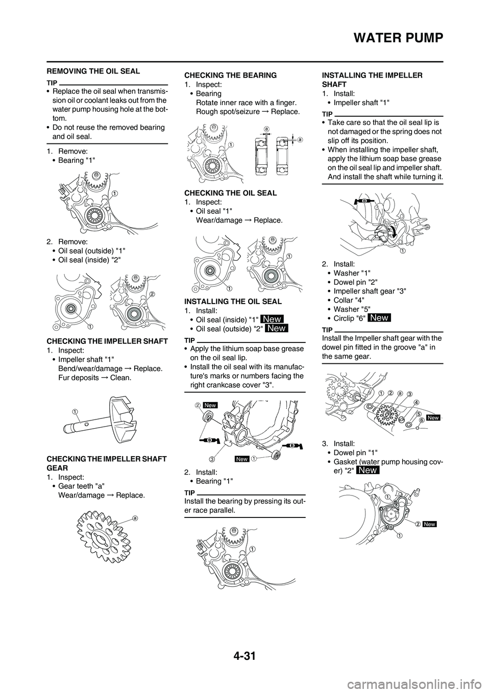
REMOVING THE OIL SEAL
• Replace the oil seal when transmis-
sion oil or coolant leaks out from the
water pump housing hole at the bot-
tom.
• Do not reuse the removed bearing
and oil seal.
1. Remove:
• Bearing "1"
2. Remove:
• Oil seal (outside) "1"
• Oil seal (inside) "2"
CHECKING THE IMPELLER SHAFT
1. Inspect:
• Impeller shaft "1"
Bend/wear/damage→Replace.
Fur deposits→Clean.
CHECKING THE IMPELLER SHAFT
GEAR
1. Inspect:
• Gear teeth "a"
Wear/damage→Replace.CHECKING THE BEARING
1. Inspect:
•Bearing
Rotate inner race with a finger.
Rough spot/seizure→Replace.
CHECKING THE OIL SEAL
1. Inspect:
• Oil seal "1"
Wear/damage→Replace.
INSTALLING THE OIL SEAL
1. Install:
• Oil seal (inside) "1"
• Oil seal (outside) "2"
• Apply the lithium soap base grease
on the oil seal lip.
• Install the oil seal with its manufac-
ture's marks or numbers facing the
right crankcase cover "3".
2. Install:
•Bearing "1"
Install the bearing by pressing its out-
er race parallel.
INSTALLING THE IMPELLER
SHAFT
1. Install:
• Impeller shaft "1"
• Take care so that the oil seal lip is
not damaged or the spring does not
slip off its position.
• When installing the impeller shaft,
apply the lithium soap base grease
on the oil seal lip and impeller shaft.
And install the shaft while turning it.
2. Install:
• Washer "1"
• Dowel pin "2"
• Impeller shaft gear "3"
•Collar "4"
• Washer "5"
• Circlip "6"
Install the Impeller shaft gear with the
dowel pin fitted in the groove "a" in
the same gear.
3. Install:
• Dowel pin "1"
• Gasket (water pump housing cov-
er) "2"
Page 100 of 166
4-40
CRANKCASE AND CRANKSHAFT
9 Crankshaft 1 Refer to removal section.
10 Oil seal 2
11 Bearing 2 Refer to removal section. Order Part name Q'ty Remarks
30 Nm (3.0 m kg, 22 ft lb)10 Nm (1.0 m kg, 7.2 ft lb)
20 Nm (2.0 m kg, 14 ft lb)
14 Nm (1.4 m kg, 10 ft lb)
Page 101 of 166

4-41
CRANKCASE AND CRANKSHAFT
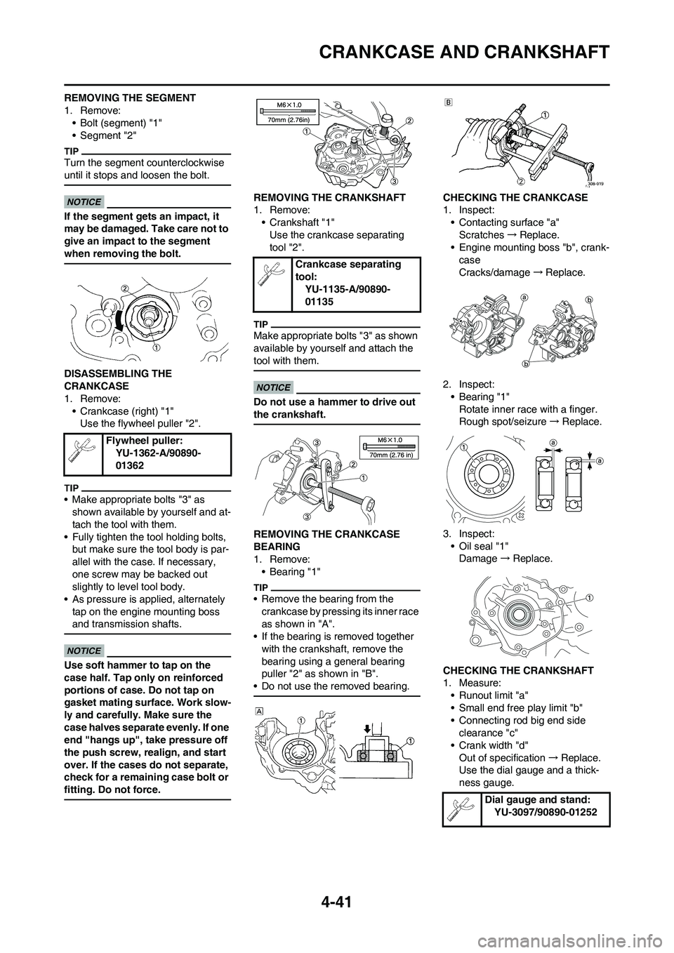
REMOVING THE SEGMENT
1. Remove:
• Bolt (segment) "1"
• Segment "2"
Turn the segment counterclockwise
until it stops and loosen the bolt.
If the segment gets an impact, it
may be damaged. Take care not to
give an impact to the segment
when removing the bolt.
DISASSEMBLING THE
CRANKCASE
1. Remove:
• Crankcase (right) "1"
Use the flywheel puller "2".
• Make appropriate bolts "3" as
shown available by yourself and at-
tach the tool with them.
• Fully tighten the tool holding bolts,
but make sure the tool body is par-
allel with the case. If necessary,
one screw may be backed out
slightly to level tool body.
• As pressure is applied, alternately
tap on the engine mounting boss
and transmission shafts.
Use soft hammer to tap on the
case half. Tap only on reinforced
portions of case. Do not tap on
gasket mating surface. Work slow-
ly and carefully. Make sure the
case halves separate evenly. If one
end "hangs up", take pressure off
the push screw, realign, and start
over. If the cases do not separate,
check for a remaining case bolt or
fitting. Do not force.
REMOVING THE CRANKSHAFT
1. Remove:
• Crankshaft "1"
Use the crankcase separating
tool "2".
Make appropriate bolts "3" as shown
available by yourself and attach the
tool with them.
Do not use a hammer to drive out
the crankshaft.
REMOVING THE CRANKCASE
BEARING
1. Remove:
•Bearing "1"
• Remove the bearing from the
crankcase by pressing its inner race
as shown in "A".
• If the bearing is removed together
with the crankshaft, remove the
bearing using a general bearing
puller "2" as shown in "B".
• Do not use the removed bearing.
CHECKING THE CRANKCASE
1. Inspect:
• Contacting surface "a"
Scratches→Replace.
• Engine mounting boss "b", crank-
case
Cracks/damage→Replace.
2. Inspect:
• Bearing "1"
Rotate inner race with a finger.
Rough spot/seizure→Replace.
3. Inspect:
• Oil seal "1"
Damage→Replace.
CHECKING THE CRANKSHAFT
1. Measure:
• Runout limit "a"
• Small end free play limit "b"
• Connecting rod big end side
clearance "c"
• Crank width "d"
Out of specification→Replace.
Use the dial gauge and a thick-
ness gauge. Flywheel puller:
YU-1362-A/90890-
01362
Crankcase separating
tool:
YU-1135-A/90890-
01135
Dial gauge and stand:
YU-3097/90890-01252
Page 102 of 166

4-42
CRANKCASE AND CRANKSHAFT
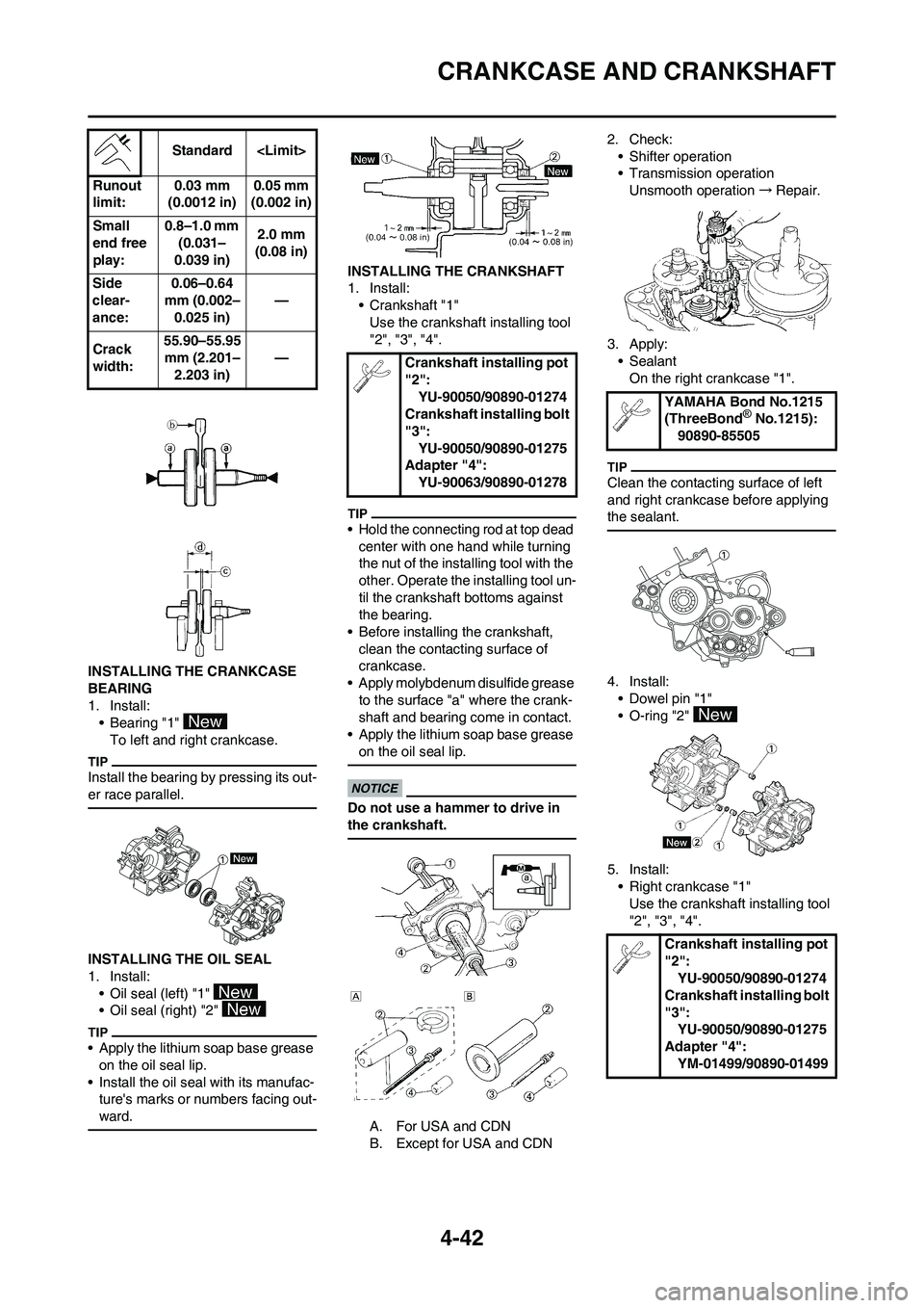
INSTALLING THE CRANKCASE
BEARING
1. Install:
• Bearing "1"
To left and right crankcase.
Install the bearing by pressing its out-
er race parallel.
INSTALLING THE OIL SEAL
1. Install:
• Oil seal (left) "1"
• Oil seal (right) "2"
• Apply the lithium soap base grease
on the oil seal lip.
• Install the oil seal with its manufac-
ture's marks or numbers facing out-
ward.
INSTALLING THE CRANKSHAFT
1. Install:
• Crankshaft "1"
Use the crankshaft installing tool
"2", "3", "4".
• Hold the connecting rod at top dead
center with one hand while turning
the nut of the installing tool with the
other. Operate the installing tool un-
til the crankshaft bottoms against
the bearing.
• Before installing the crankshaft,
clean the contacting surface of
crankcase.
• Apply molybdenum disulfide grease
to the surface "a" where the crank-
shaft and bearing come in contact.
• Apply the lithium soap base grease
on the oil seal lip.
Do not use a hammer to drive in
the crankshaft.
A. For USA and CDN
B. Except for USA and CDN2. Check:
• Shifter operation
• Transmission operation
Unsmooth operation→Repair.
3. Apply:
• Sealant
On the right crankcase "1".
Clean the contacting surface of left
and right crankcase before applying
the sealant.
4. Install:
• Dowel pin "1"
• O-ring "2"
5. Install:
• Right crankcase "1"
Use the crankshaft installing tool
"2", "3", "4". Standard
Runout
limit:0.03 mm
(0.0012 in)0.05 mm
(0.002 in)
Small
end free
play:0.8–1.0 mm
(0.031–
0.039 in)2.0 mm
(0.08 in)
Side
clear-
ance:0.06–0.64
mm (0.002–
0.025 in)—
Crack
width:55.90–55.95
mm (2.201–
2.203 in)—
Crankshaft installing pot
"2":
YU-90050/90890-01274
Crankshaft installing bolt
"3":
YU-90050/90890-01275
Adapter "4":
YU-90063/90890-01278
YAMAHA Bond No.1215
(ThreeBond® No.1215):
90890-85505
Crankshaft installing pot
"2":
YU-90050/90890-01274
Crankshaft installing bolt
"3":
YU-90050/90890-01275
Adapter "4":
YM-01499/90890-01499