2011 YAMAHA YZ125LC oil
[x] Cancel search: oilPage 26 of 166
2-2
MAINTENANCE SPECIFICATIONS
MAINTENANCE SPECIFICATIONS
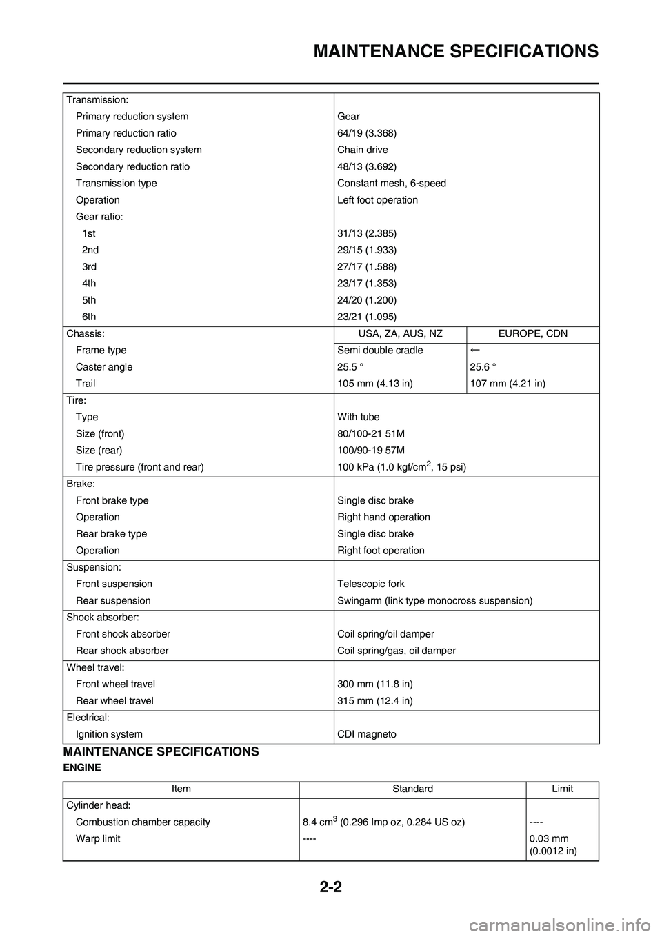
ENGINETransmission:
Primary reduction system Gear
Primary reduction ratio 64/19 (3.368)
Secondary reduction system Chain drive
Secondary reduction ratio 48/13 (3.692)
Transmission type Constant mesh, 6-speed
Operation Left foot operation
Gear ratio:
1st 31/13 (2.385)
2nd 29/15 (1.933)
3rd 27/17 (1.588)
4th 23/17 (1.353)
5th 24/20 (1.200)
6th 23/21 (1.095)
Chassis: USA, ZA, AUS, NZ EUROPE, CDN
Frame type Semi double cradle←
Caster angle 25.5 ° 25.6 °
Trail 105 mm (4.13 in) 107 mm (4.21 in)
Tire:
Type With tube
Size (front) 80/100-21 51M
Size (rear) 100/90-19 57M
Tire pressure (front and rear) 100 kPa (1.0 kgf/cm
2, 15 psi)
Brake:
Front brake type Single disc brake
Operation Right hand operation
Rear brake type Single disc brake
Operation Right foot operation
Suspension:
Front suspension Telescopic fork
Rear suspension Swingarm (link type monocross suspension)
Shock absorber:
Front shock absorber Coil spring/oil damper
Rear shock absorber Coil spring/gas, oil damper
Wheel travel:
Front wheel travel 300 mm (11.8 in)
Rear wheel travel 315 mm (12.4 in)
Electrical:
Ignition system CDI magneto
Item Standard Limit
Cylinder head:
Combustion chamber capacity 8.4 cm
3 (0.296 Imp oz, 0.284 US oz) ----
Warp limit ---- 0.03 mm
(0.0012 in)
Page 28 of 166
2-4
MAINTENANCE SPECIFICATIONS
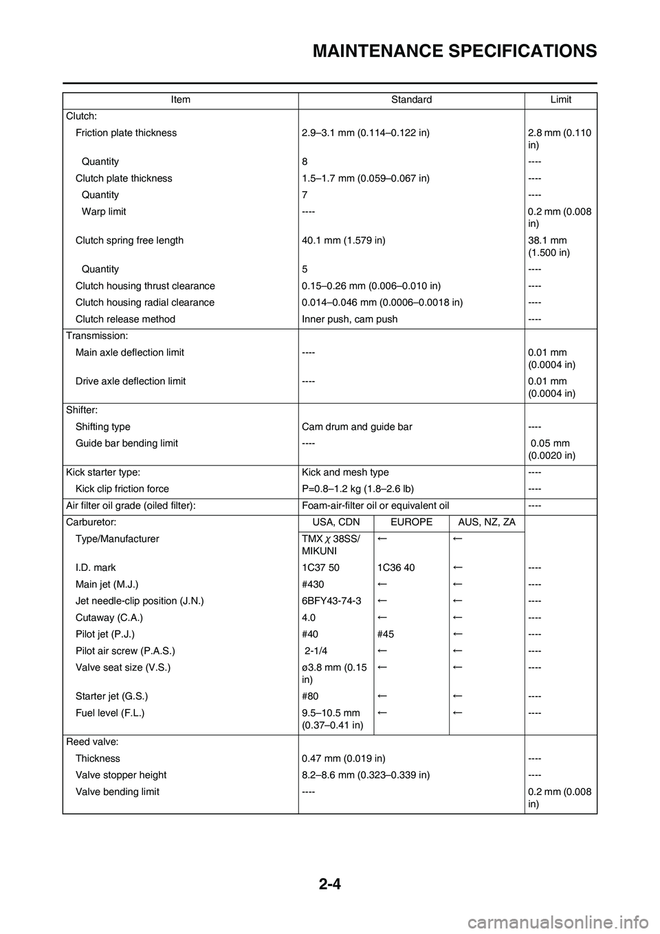
Clutch:Friction plate thickness 2.9–3.1 mm (0.114–0.122 in) 2.8 mm (0.110
in)
Quantity 8 ----
Clutch plate thickness 1.5 –1.7 mm (0.059–0.067 in) ----
Quantity 7 ----
Warp limit ---- 0.2 mm (0.008 in)
Clutch spring free length 40.1 mm (1.579 in) 38.1 mm (1.500 in)
Quantity 5 ----
Clutch housing thrust clearance 0.15–0.26 mm (0.006–0.010 in) ----
Clutch housing radial clearance 0.014–0.046 mm (0.0006–0.0018 in) ----
Clutch release method Inner push, cam push ----
Transmission: Main axle deflec tion limit ---- 0.01 mm
(0.0004 in)
Drive axle deflection limit ---- 0.01 mm (0.0004 in)
Shifter: Shifting type Cam drum and guide bar ----
Guide bar bending limit ---- 0.05 mm (0.0020 in)
Kick starter type: Kick and mesh type ---- Kick clip friction force P=0 .8–1.2 kg (1.8–2.6 lb) ----
Air filter oil grade (oiled filter): Foam-air-filter oil or equivalent oil ----
Carburetor: USA, CDN EUROPE AUS, NZ, ZA Type/Manufacturer TMX χ38SS/
MIKUNI ←←
I.D. mark 1C37 50 1C36 40 ←----
Main jet (M.J.) #430 ←←----
Jet needle-clip position (J.N.) 6BFY43-74-3 ←←----
Cutaway (C.A.) 4.0 ←←----
Pilot jet (P.J.) #40 #45 ←----
Pilot air screw (P.A.S.) 2-1/4 ←←----
Valve seat size (V.S.) ø3.8 mm (0.15 in)←←
----
Starter jet (G.S.) #80 ←←----
Fuel level (F.L.) 9.5–10.5 mm (0.37–0.41 in)←←
----
Reed valve: Thickness 0.47 mm (0.019 in) ----
Valve stopper height 8.2–8.6 mm (0.323–0.339 in) ----
Valve bending limi t ---- 0.2 mm (0.008
in)
Item Standard Limit
Page 29 of 166
2-5
MAINTENANCE SPECIFICATIONS
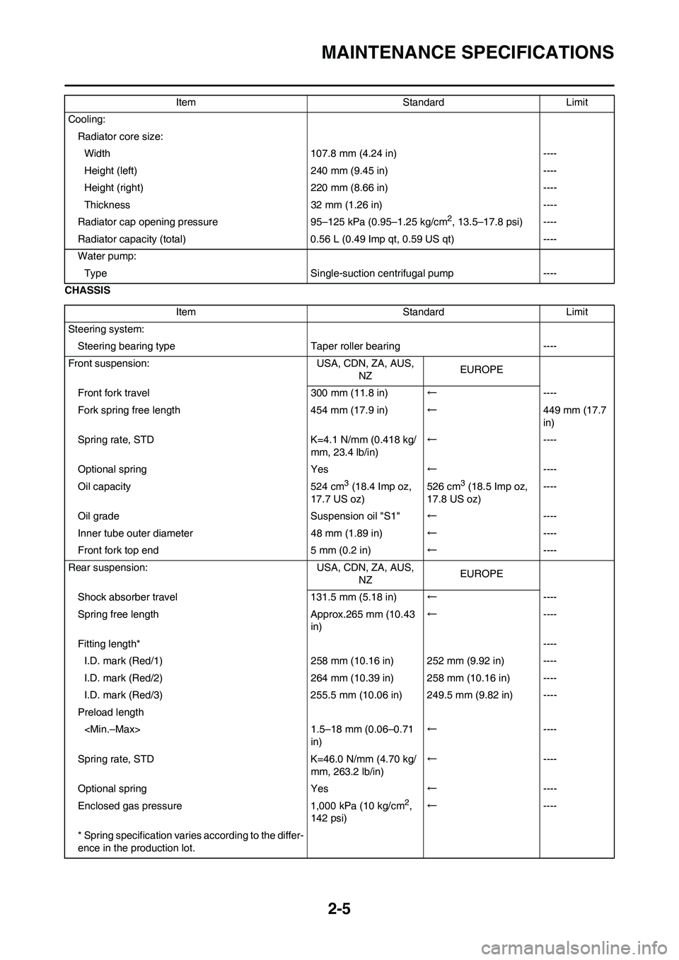
CHASSISCooling:
Radiator core size:
Width 107.8 mm (4.24 in) ----
Height (left) 240 mm (9.45 in) ----
Height (right) 220 mm (8.66 in) ----
Thickness 32 mm (1.26 in) ----
Radiator cap opening pressure 95–125 kPa (0.95–1.25 kg/cm
2, 13.5–17.8 psi) ----
Radiator capacity (total) 0.56 L (0.49 Imp qt, 0.59 US qt) ----
Water pump:
Type Single-suction centrifugal pump ----
Item Standard Limit
Steering system:
Steering bearing typeTaper roller bearing ----
Front suspension: USA, CDN, ZA, AUS,
NZEUROPE
Front fork travel 300 mm (11.8 in)←----
Fork spring free length 454 mm (17.9 in)←449 mm (17.7
in)
Spring rate, STD K=4.1 N/mm (0.418 kg/
mm, 23.4 lb/in)←----
Optional spring Yes←----
Oil capacity 524 cm
3 (18.4 Imp oz,
17.7 US oz)526 cm3 (18.5 Imp oz,
17.8 US oz)----
Oil grade Suspension oil "S1"←----
Inner tube outer diameter 48 mm (1.89 in)←----
Front fork top end 5 mm (0.2 in)←----
Rear suspension: USA, CDN, ZA, AUS,
NZEUROPE
Shock absorber travel 131.5 mm (5.18 in)←----
Spring free length Approx.265 mm (10.43
in)←----
Fitting length*----
I.D. mark (Red/1) 258 mm (10.16 in) 252 mm (9.92 in) ----
I.D. mark (Red/2) 264 mm (10.39 in) 258 mm (10.16 in) ----
I.D. mark (Red/3) 255.5 mm (10.06 in) 249.5 mm (9.82 in) ----
Preload length
in)←----
Spring rate, STD K=46.0 N/mm (4.70 kg/
mm, 263.2 lb/in)←----
Optional spring Yes←----
Enclosed gas pressure 1,000 kPa (10 kg/cm
2,
142 psi)←----
* Spring specification varies according to the differ-
ence in the production lot.Item Standard Limit
Page 31 of 166

2-7
TIGHTENING TORQUES
ELECTRICAL
TIGHTENING TORQUES
ENGINE
△- marked portion shall be checked for torque tightening after break-in or before each race.
Item Standard Limit
Ignition system:
Ignition timing (B.T.D.C.) 0.48 mm (0.019 in) ----
Advancer type Electrical ----
CDI:
Magneto-model (stator)/Manufacturer 1C3-10/YAMAHA ----
Charging coil 1 resistance (color) 720–1,080 Ωat 20 °C (68 °F) (Green/
White-Black/Red)----
Charging coil 2 resistance (color) 44–66 Ωat 20 °C (68 °F) (Black-Green/
Blue)----
Pickup coil resistance (color) 248–372 Ωat 20 °C (68 °F) (White/Blue-
White/Red)----
CDI unit-model/manufacturer 1C3-10/YAMAHA ----
Ignition coil:
Model/manufacturer 1C3-00/YAMAHA ----
Minimum spark gap 6 mm (0.24 in) ----
Primary winding resistance 0.24–0.36 Ωat 20 °C (68 °F) ----
Secondary winding resistance 5.7–8.5 kΩat 20 °C (68 °F) ----
Spark plug cap:
Resistance 4–6 kΩat 20 °C (68 °F) ----
Part to be tightened Thread size Q'tyTightening torque
Nm m•kg ft•lb
Spark plug M14S × 1.25 1 20 2.0 14
Cylinder head (nut) M8 × 1.25 5 28 2.8 20
Cylinder head (stud) M8 × 1.25 5 13 1.3 9.4
Cylinder (nut) M8 × 1.25 4 30 3.0 22
Cylinder (stud) M10 × 1.25 4 13 1.3 9.4
Power valve:
Cover M5 × 0.8 4 5 0.5 3.6
Link lever M4 × 0.7 1 4 0.4 2.9
Holder (power valve) M5 × 0.8 4 8 0.8 5.8
Push rod M5 × 0.8 1 5 0.5 3.6
Thrust plate M5 × 0.8 1 4 0.4 2.9
Governor fork M4 × 0.7 2 5 0.5 3.6
Housing M5 × 0.8 3 4 0.4 2.9
Water pump housing cover M6 × 1.0 4 10 1.0 7.2
Coolant drain bolt M6 × 1.0 1 10 1.0 7.2
Radiator M6 × 1.0 6 10 1.0 7.2
Radiator panel M6 × 1.0 2 10 1.0 7.2
Radiator hose clamp M6 × 1.0 8 2 0.2 1.4
Air filter element M6 × 1.0 1 2 0.2 1.4
Page 32 of 166
2-8
TIGHTENING TORQUES
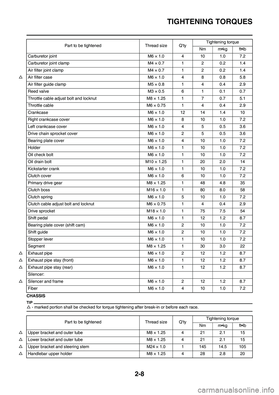
CHASSIS
△- marked portion shall be checked for torque ti ghtening after break-in or before each race.
Carburetor joint M6 × 1.0 4 10 1.0 7.2
Carburetor joint clamp M4 × 0.7 1 2 0.2 1.4
Air filter joint clamp M4 × 0.7 1 2 0.2 1.4
△ Air filter case M6 × 1.0 4 8 0.8 5.8
Air filter guide clamp M5 × 0.8 1 4 0.4 2.9
Reed valve M3 × 0.5 6 1 0.1 0.7
Throttle cable adjust bolt and locknut M8 × 1.25 1 7 0.7 5.1
Throttle cable M6 × 0.75 1 4 0.4 2.9
Crankcase M6 × 1.0 12 14 1.4 10
Right crankcase cove r M6 × 1.0 8 10 1.0 7.2
Left crankcase cover M6 × 1.0 4 5 0.5 3.6
Drive chain sprocket cover M6 × 1.0 2 5 0.5 3.6
Bearing plate cover M6 × 1.0 4 10 1.0 7.2
Holder M6 × 1.0 1 10 1.0 7.2
Oil check bolt M6 × 1.0 1 10 1.0 7.2
Oil drain bolt M10 × 1.25 1 20 2.0 14
Kickstarter crank M6 × 1.0 1 10 1.0 7.2
Clutch cover M6 × 1.0 6 10 1.0 7.2
Primary drive gear M8 × 1.25 1 48 4.8 35
Clutch boss M16 × 1.0 1 80 8.0 58
Clutch spring M6 × 1.0 5 10 1.0 7.2
Clutch cable adjust bolt and locknut M6 × 0.75 1 4 0.4 2.9
Drive sprocket M18 × 1.0 1 75 7.5 54
Shift pedal M6 × 1.0 1 12 1.2 8.7
Bearing plate cover (shift cam) M6 × 1.0 2 10 1.0 7.2
Shift guide M6 × 1.0 2 10 1.0 7.2
Stopper lever M6 × 1.0 1 10 1.0 7.2
Segment M8 × 1.25 1 30 3.0 22
△ Exhaust pipe M6 × 1.0 2 12 1.2 8.7
△ Exhaust pipe stay (front) M6 × 1.0 1 12 1.2 8.7
△ Exhaust pipe stay (rear) M6 × 1.0 1 12 1.2 8.7
Silencer:
△ Silencer and frame M6 × 1.0 2 12 1.2 8.7
Fiber M6 × 1.0 4 10 1.0 7.2 Part to be tightened Thread size Q'ty
Tightening torque
Nm m•kg ft•lb
Part to be tightened Thread size Q'ty Tightening torque
Nm m•kg ft•lb
△ Upper bracket and outer tube M8 × 1.25 4 21 2.1 15
△ Lower bracket and outer tube M8 × 1.25 4 21 2.1 15
△ Upper bracket and steeri ng stem M24 × 1.0 1 145 14.5 105
△ Handlebar upper holder M8 × 1.25 4 28 2.8 20
Page 34 of 166
2-10
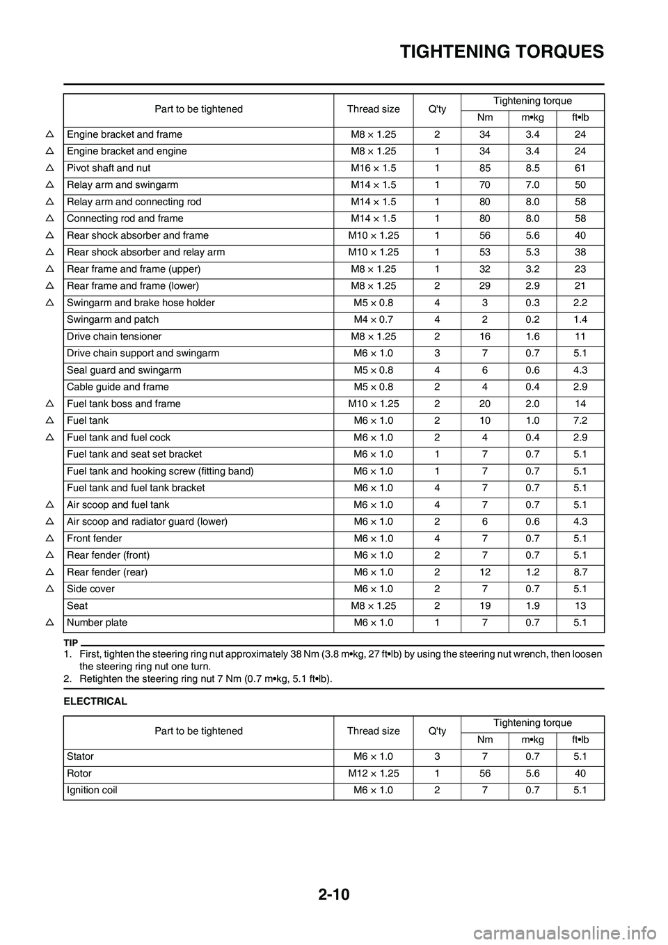
TIGHTENING TORQUES
1. First, tighten the steering ring nut approximately 38 Nm (3.8 m•kg, 27 ft•lb) by using the steering nut wrench, then loosen
the steering ring nut one turn.
2. Retighten the steering ring nut 7 Nm (0.7 m•kg, 5.1 ft•lb).
ELECTRICAL △Engine bracket and frame M8 × 1.25 2 34 3.4 24
△Engine bracket and engine M8 × 1.25 1 34 3.4 24
△Pivot shaft and nut M16 × 1.5 1 85 8.5 61
△Relay arm and swingarm M14 × 1.5 1 70 7.0 50
△Relay arm and connecting rod M14 × 1.5 1 80 8.0 58
△Connecting rod and frame M14 × 1.5 1 80 8.0 58
△Rear shock absorber and frame M10 × 1.25 1 56 5.6 40
△Rear shock absorber and relay arm M10 × 1.25 1 53 5.3 38
△Rear frame and frame (upper) M8 × 1.25 1 32 3.2 23
△Rear frame and frame (lower) M8 × 1.25 2 29 2.9 21
△Swingarm and brake hose holder M5 × 0.8 4 3 0.3 2.2
Swingarm and patch M4 × 0.7 4 2 0.2 1.4
Drive chain tensioner M8 × 1.25 2 16 1.6 11
Drive chain support and swingarm M6 × 1.0 3 7 0.7 5.1
Seal guard and swingarm M5 × 0.8 4 6 0.6 4.3
Cable guide and frame M5 × 0.8 2 4 0.4 2.9
△Fuel tank boss and frame M10 × 1.25 2 20 2.0 14
△Fuel tank M6 × 1.0 2 10 1.0 7.2
△Fuel tank and fuel cock M6 × 1.0 2 4 0.4 2.9
Fuel tank and seat set bracket M6 × 1.0 1 7 0.7 5.1
Fuel tank and hooking screw (fitting band) M6 × 1.0 1 7 0.7 5.1
Fuel tank and fuel tank bracket M6 × 1.0 4 7 0.7 5.1
△Air scoop and fuel tank M6 × 1.0 4 7 0.7 5.1
△Air scoop and radiator guard (lower) M6 × 1.0 2 6 0.6 4.3
△Front fender M6 × 1.0 4 7 0.7 5.1
△Rear fender (front) M6 × 1.0 2 7 0.7 5.1
△Rear fender (rear) M6 × 1.0 2 12 1.2 8.7
△Side cover M6 × 1.0 2 7 0.7 5.1
Seat M8 × 1.25 2 19 1.9 13
△Number plate M6 × 1.0 1 7 0.7 5.1Part to be tightened Thread size Q'tyTightening torque
Nm m•kg ft•lb
Part to be tightened Thread size Q'tyTightening torque
Nm m•kg ft•lb
Stator M6 × 1.0 3 7 0.7 5.1
Rotor M12 × 1.25 1 56 5.6 40
Ignition coil M6 × 1.0 2 7 0.7 5.1
Page 37 of 166

2-13
CABLE ROUTING DIAGRAM
D. Install the ignition coil, side core
and ground lead together to the
frame. Take care to fasten the
ground lead so that its terminal
is within the indicated range.
E. Clamp the throttle cable and
high tension cord to the frame.
F. Clamp the clutch cable to the left
engine bracket. Clamp the
clutch cable below the position-
ing grommet.
G. Pass the air vent hose back of
the throttle cable.
H. Pass the air vent hose, overflow
hose and crankcase breather
hose between the frame and
connecting rod.
I. Pass the radiator breather hose
and YPVS breather hose out-
side the engine bracket and in-
side the down tube. Then pass
the radiator breather hose inside
the YPVS breather hose.
J. Clamp the CDI magneto lead,
radiator breather hose and
YPVS breather hose to the
frame.
K. Clamp to the frame the CDI
magneto lead and radiator
breather hose. Take care to
clamp them above the projection
on the frame.
L. Locate the clamp ends in the ar-
rowed range.
M. Pass the air vent hose, overflow
hose and crankcase breather
hose so that they do not contact
the rear shock absorber.
N. Bring the connector cover into
contact with the coupler.
Page 38 of 166

2-14
CABLE ROUTING DIAGRAM
1. High tension cord
2. "ENGINE STOP" button lead
3. Ignition coil lead
4. Clamp
5. CDI unit
6. CDI unit band
7. Radiator breather hose
8. CDI magneto lead
9. Connector cover
10. Throttle cable
11. Clutch cable12. CDI unit stay
A. Pass the high tension cord to the
left of the radiator hose.
B. Using a plastic locking tie, clamp
the "ENGINE STOP" button
lead, ignition coil lead and CDI
magneto lead together with the
clamp ends backward and then
cut off the tie end.C. Clamp to the frame the throttle
cable, clutch cable, ignition coil
lead and "ENGINE STOP" but-
ton lead. In so doing, clamp the
ignition coil lead and "ENGINE
STOP" button lead at their pro-
tecting tubes. Tighten the clamp
so that the "ENGINE STOP" but-
ton lead is not pulled when the
handlebar is turned to the right
and left.