Page 17 of 140
3-1
3
EBU17680
DESCRIPTION
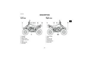
EBU17690Left view
EBU17700Right view
1. Headlight
2. Fuel cock
3. Starter (choke)
4. Throttle stop screw
5. Fuse
6. Tail/brake light
7. Shift pedal
7 123456
1. Spark arrester
2. Seat
3. Fuel tank cap
4. Steering lock
5. Oil filter element
6. Brake pedal
5 123
4
6
U33B70E0.book Page 1 Wednesday, June 11, 2008 1:38 PM
Page 18 of 140
3-2
3
EBU17712Controls and instruments
TIPThe ATV you have purchased may differ slightlyfrom the figures shown in this manual.
1. Clutch lever
2. Handlebar switches
3. Speedometer unit
4. Parking brake lever
5. Main switch
6. Engine stop switch
7. Throttle lever
8. Brake lever
1
4 2
3
5
7
6
8
U33B70E0.book Page 2 Wednesday, June 11, 2008 1:38 PM
Page 19 of 140
4-1
4
EBU17732
INSTRUMENT AND CONTROL FUNCTIONS
EBUM0020Main switch The positions of the main switch are as follows:
ON
All electrical systems are supplied with power. The
auxiliary light, meter lighting and taillight come on
when the light switch is on, and the engine can be
started. The key cannot be removed.
OFF
All electrical systems are off. The key can be re-
moved.
1. Main switch
OFF ON
1
U33B70E0.book Page 1 Wednesday, June 11, 2008 1:38 PM
Page 20 of 140
4-2
4
EBU17791Indicator lights EBU27970Turn signal indicator light“”
This indicator light flashes when the turn signal
switch is pushed to the left or right.EBU17860Neutral indicator light“”
This indicator light comes on when the transmis-
sion is in the neutral position.
EBU27980High beam indicator light“”
This indicator light comes on when the high beam
of the headlight is switched on.EBU28050Speedometer The speedometer shows the riding speed. This
speedometer is equipped with an odometer. The
odometer shows the total distance traveled.
1. High beam indicator light “ ”
2. Turn signal indicator light “ ”
3. Neutral indicator light “N”
3 2 1
1. Speedometer
2. Odometer
U33B70E0.book Page 2 Wednesday, June 11, 2008 1:38 PM
Page 21 of 140
4-3
4
EBU18061Handlebar switches
EBU18080Engine stop switch“/”
Set this switch to “ ” before starting the engine.
The engine stop switch controls the ignition and
stops the engine when it is running. Use this switch
to stop the engine in an emergency situation. The
engine will not start or run when this switch is set
to “ ”.EBU18100Start switch“”
Push this switch to crank the engine with the start-
er.
1. Light switch “ / / ”
2. Start switch “ ”
3. Horn switch “ ”
4. Hazard switch “ ”
5. Turn signal switch “ / ”
12345
1. Engine stop switch “ / ”
U33B70E0.book Page 3 Wednesday, June 11, 2008 1:38 PM
Page 22 of 140

4-4
4
NOTICEECB00050See the starting instructions on page 6-1 priorto starting the engine.EBU28061Light switch“//”
Set the switch to “ ” to turn on the high beam.
Set this switch to “ ” to turn on the low beam.
Set the switch to “ ” to turn off the headlight.NOTICEECB00030Do not use the headlight with the engine turned
off for an extended period of time, otherwise
the battery may discharge to the point that the
starter motor will not operate properly. If this
should happen, remove the battery and re-charge it.EBU27990Turn signal switch“/”
To signal a right-hand turn, push this switch
to “ ”. To signal a left-hand turn, push this switch
to “ ”. When released, the switch returns to the
center position. To cancel the turn signal lights,
push the switch in after it has returned to the center
position.
EBU18170Horn switch“”
Press the switch to sound the horn.EBUM0220Hazard switch“”
Turn this switch to “ ” to turn on the hazard lights
(simultaneous flashing of all turn signal lights).
The hazard lights are used in case of an emergen-
cy or to warn other drivers when your vehicle is
stopped where it might be a traffic hazard.NOTICEECB00860Do not use the hazard lights for an extended
length of time with the engine not running, oth-erwise the battery may discharge.EBU18280Throttle lever Once the engine is running, movement of the throt-
tle lever will increase the engine speed.
Regulate the speed of the ATV by varying the
throttle position. Because the throttle is spring-
loaded, the ATV will decelerate, and the engine will
return to an idle any time the hand is removed from
the throttle lever.
U33B70E0.book Page 4 Wednesday, June 11, 2008 1:38 PM
Page 23 of 140

4-5
4
Before starting the engine, check the throttle to be
sure it is operating smoothly. Make sure it returns
to the idle position as soon as the lever is released.
WARNING
EWB00250Malfunction of the throttle could make it diffi-
cult to speed up or slow down when you need
to. This could cause an accident. Check the op-
eration of the throttle lever before you start the
engine. If the throttle does not work smoothly,
check for the cause. Correct the problem be-fore riding the ATV or consult a Yamaha dealer.
EBU18321Speed limiter Your ATV was delivered with an adjustable speed
limiter. The speed limiter keeps the throttle from
fully opening, even when the throttle lever is
pushed to the maximum.
1. Loosen the locknut.
2. To increase the maximum engine power avail-
able and the maximum speed of the ATV, turn
the adjusting screw in direction (a). To de-
crease the maximum engine power available
and the maximum speed of the ATV, turn the
adjusting screw in direction (b).
1. Throttle lever
1. Locknut
2. Adjusting screw
3. No more than 12 mm (0.47 in)
31
2
(a)(b)
U33B70E0.book Page 5 Wednesday, June 11, 2008 1:38 PM
Page 24 of 140

4-6
43. Tighten the locknut.
WARNING
EWB00240Improper adjustment of the speed limiter and
throttle could cause throttle cable damage or
improper throttle operation. You could lose
control, have an accident or be injured. Do not
turn the adjusting screw out more than 12 mm
(0.47 in) or the throttle cable could be dam-
aged. Always make sure the throttle lever free
play is adjusted to 2.0–4.0 mm (0.08–0.16 in).(See page 8-20.)EBU18382Clutch lever The clutch lever is located on the left handlebar
and the ignition circuit cut-off system is incorporat-
ed in the clutch lever holder. To disengage the
clutch, pull the clutch lever toward the handlebar
grip. To engage the clutch, release the clutch lever.
The clutch lever should be pulled rapidly and re-
leased slowly for smooth clutch operation. (See
page 6-1 for a description of the ignition circuit cut-
off system.)
EBU18411Brake lever (YFM250R-W)The brake lever is located at the right handlebar
grip. To apply the front brake, pull the brake lever
toward the handlebar grip.1. Clutch lever
U33B70E0.book Page 6 Wednesday, June 11, 2008 1:38 PM