Page 57 of 90
 at the
inner edge of the throttle g")
PERIODIC MAINTENANCE AND ADJUSTMENT
6-15
6
EAU21384
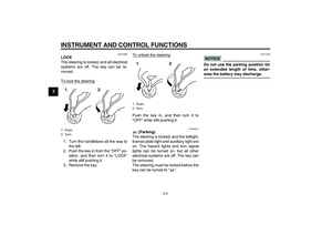
Checking the throttle grip free
play The throttle grip free play should mea-
sure 4.0–6.0 mm (0.16–0.24 in) at the
inner edge of the throttle grip. Periodi-
cally check the throttle grip free play
and, if necessary, have a Yamaha deal-
er adjust it.
EAU21401
Valve clearance The valve clearance changes with use,
resulting in improper air-fuel mixture
and/or engine noise. To prevent this
from occurring, the valve clearance
must be adjusted by a Yamaha dealer
at the intervals specified in the periodic
maintenance and lubrication chart.
EAU21565
Tires To maximize the performance, durabil-
ity, and safe operation of your motorcy-
cle, note the following points regarding
the specified tires.
Tire air pressure
The tire air pressure should be checked
and, if necessary, adjusted before each
ride.
WARNING
EWA10503
Operation of this vehicle with im-
proper tire pressure may cause se-
vere injury or death from loss of
control.�
The tire air pressure must be
checked and adjusted on cold
tires (i.e., when the temperature
of the tires equals the ambient
temperature).
�
The tire air pressure must be ad-
justed in accordance with the
riding speed and with the total
weight of rider, passenger, car-
go, and accessories approved
for this model.
1. Throttle grip free play
U11CE4E0.book Page 15 Friday, December 3, 2010 9:12 AM
Page 58 of 90

PERIODIC MAINTENANCE AND ADJUSTMENT
6-16
6
WARNING
EWA10511
Never overload your vehicle. Opera-
tion of an overloaded vehicle could
cause an accident.
Tire inspection
The tires must be checked before each
ride. If the center tread depth reaches
the specified limit, if the tire has a nail or
glass fragments in it, or if the sidewall is
cracked, have a Yamaha dealer re-
place the tire immediately.TIPThe tire tread depth limits may differ
from country to country. Always comply
with the local regulations.
Tire information
This motorcycle is equipped with tube-
less tires, tire air valves and cast
wheels.
WARNING
EWA10461
The front and rear tires should be of
the same make and design, other-
wise the handling characteristics of
the vehicle may be different, which
could lead to an accident.After extensive tests, only the tires list-
ed below have been approved for this
model by Yamaha Motor Co., Ltd.
Tire air pressure (measured on cold
tires):
0–90 kg (0–198 lb):
Front:
250 kPa (2.50 kgf/cm², 36 psi)
Rear:
280 kPa (2.80 kgf/cm², 41 psi)
90–209 kg (198–461 lb):
Front:
250 kPa (2.50 kgf/cm², 36 psi)
Rear:
280 kPa (2.80 kgf/cm², 41 psi)
Maximum load*:
209 kg (461 lb)
* Total weight of rider, passenger, car-
go and accessories
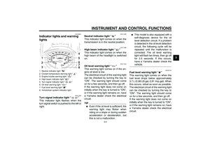
1. Tire sidewall
2. Tire tread depthMinimum tire tread depth (front and
rear):
1.6 mm (0.06 in)
Front tire:
Size:
130/90 16M/C 67H
Manufacturer/model:
DUNLOP/D404F X
BRIDGESTONE/EXEDRA G721
Rear tire:
Size:
170/70B 16M/C 75H
Manufacturer/model:
DUNLOP/K555
BRIDGESTONE/EXEDRA G722
G
U11CE4E0.book Page 16 Friday, December 3, 2010 9:12 AM
Page 59 of 90

PERIODIC MAINTENANCE AND ADJUSTMENT
6-17
6
WARNING
EWA10471
�
Have a Yamaha dealer replace
excessively worn tires. Besides
being illegal, operating the vehi-
cle with excessively worn tires
decreases riding stability and
can lead to loss of control.
�
The replacement of all wheel
and brake-related parts, includ-
ing the tires, should be left to a
Yamaha dealer, who has the
necessary professional knowl-
edge and experience to do so.
�
Ride at moderate speeds after
changing a tire since the tire
surface must first be “broken
in” for it to develop its optimal
characteristics.
EAU21962
Cast wheels To maximize the performance, durabil-
ity, and safe operation of your vehicle,
note the following points regarding the
specified wheels.�
The wheel rims should be checked
for cracks, bends, warpage or oth-
er damage before each ride. If any
damage is found, have a Yamaha
dealer replace the wheel. Do not
attempt even the smallest repair to
the wheel. A deformed or cracked
wheel must be replaced.
�
The wheel should be balanced
whenever either the tire or wheel
has been changed or replaced. An
unbalanced wheel can result in
poor performance, adverse han-
dling characteristics, and a short-
ened tire life.
EAU48373
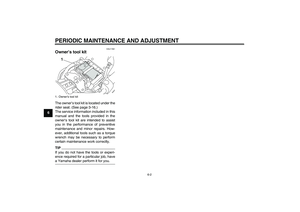
Adjusting the clutch lever free
play The clutch lever free play should mea-
sure 5.0–10.0 mm (0.20–0.39 in) as
shown. Periodically check the clutch le-
ver free play and, if necessary, adjust it
as follows.
1. Slide the rubber cover back at the
clutch lever.
2. Loosen the locknut.
3. To increase the clutch lever free
play, turn the clutch lever free play
adjusting bolt in direction (a). To
decrease the clutch lever free play,
turn the adjusting bolt in direction
(b).
U11CE4E0.book Page 17 Friday, December 3, 2010 9:12 AM
Page 60 of 90
 to loos")
PERIODIC MAINTENANCE AND ADJUSTMENT
6-18
6
TIPIf the specified clutch lever free play
could be obtained as described above,
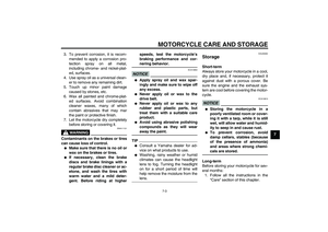
skip steps 4–7.4. Fully turn the adjusting bolt in di-
rection (a) to loosen the clutch ca-
ble.
5. Slide the rubber cover back further
down the clutch cable, and then
loosen the locknut.
6. To increase the clutch lever free
play, turn the clutch lever free play
adjusting nut in direction (a). Todecrease the clutch lever free play,
turn the adjusting nut in direction
(b).
7. Tighten the locknut at the clutch
cable, and then slide the rubber
cover to its original position.
8. Tighten the locknut at the clutch le-
ver, and then slide the rubber cov-
er to its original position.
EAU37913
Checking the brake lever free
play There should be no free play at the
brake lever end. If there is free play,
have a Yamaha dealer inspect the
brake system.
WARNING
EWA14211
A soft or spongy feeling in the brake
lever can indicate the presence of air
in the hydraulic system. If there is air
in the hydraulic system, have a
Yamaha dealer bleed the system be-
fore operating the vehicle. Air in the
hydraulic system will diminish the
1. Clutch lever free play
2. Locknut
3. Clutch lever free play adjusting bolt
4. Rubber cover1
2
3
4
1. Clutch lever free play adjusting nut
2. Locknut
3. Rubber cover
12
(a)
(b)
3
1. No brake lever free play
1
U11CE4E0.book Page 18 Friday, December 3, 2010 9:12 AM
Page 61 of 90

PERIODIC MAINTENANCE AND ADJUSTMENT
6-19
6 braking performance, which may re-
sult in loss of control and an acci-
dent.
EAU22273
Brake light switches The brake light, which is activated by
the brake pedal and brake lever, should
come on just before braking takes ef-
fect. If necessary, adjust the rear brake
light switch as follows, but the front
brake light switch should be adjusted
by a Yamaha dealer.
Turn the rear brake light switch adjust-
ing nut while holding the rear brake light
switch in place. To make the brake light
come on earlier, turn the adjusting nut
in direction (a). To make the brake light
come on later, turn the adjusting nut in
direction (b).
EAU22392
Checking the front and rear
brake pads The front and rear brake pads must be
checked for wear at the intervals spec-
ified in the periodic maintenance and
lubrication chart.
EAU22430
Front brake pads
Each front brake pad is provided with
wear indicator grooves, which allow
you to check the brake pad wear with-
out having to disassemble the brake.
To check the brake pad wear, check
the wear indicator grooves. If a brake
pad has worn to the point that the wear
1. Rear brake light switch
2. Rear brake light switch adjusting nut
(a)21
(b)
1. Brake pad wear indicator groove
U11CE4E0.book Page 19 Friday, December 3, 2010 9:12 AM
Page 62 of 90

PERIODIC MAINTENANCE AND ADJUSTMENT
6-20
6indicator grooves have almost disap-
peared, have a Yamaha dealer replace
the brake pads as a set.
EAU22500
Rear brake pads
Check each rear brake pad for damage
and measure the lining thickness. If a
brake pad is damaged or if the lining
thickness is less than 0.8 mm (0.03 in),
have a Yamaha dealer replace the
brake pads as a set.
EAU22580
Checking the brake fluid level Front brake
Rear brake
Insufficient brake fluid may allow air to
enter the brake system, possibly caus-
ing it to become ineffective.Before riding, check that the brake fluid
is above the minimum level mark and
replenish if necessary. A low brake fluid
level may indicate worn brake pads
and/or brake system leakage. If the
brake fluid level is low, be sure to check
the brake pads for wear and the brake
system for leakage.
Observe these precautions:
�
When checking the fluid level,
make sure that the top of the brake
fluid reservoir is level.
�
Use only the recommended quality
brake fluid, otherwise the rubber
seals may deteriorate, causing
leakage and poor braking perfor-
mance.
�
Refill with the same type of brake
fluid. Mixing fluids may result in a
harmful chemical reaction and
lead to poor braking performance.
1. Lining thickness
1. Minimum level mark
1. Minimum level mark
L
O
W
E
R
1
Recommended brake fluid:
DOT 4
U11CE4E0.book Page 20 Friday, December 3, 2010 9:12 AM
Page 63 of 90

PERIODIC MAINTENANCE AND ADJUSTMENT
6-21
6
�
Be careful that water does not en-
ter the brake fluid reservoir when
refilling. Water will significantly
lower the boiling point of the fluid
and may result in vapor lock.
�
Brake fluid may deteriorate paint-
ed surfaces or plastic parts. Al-
ways clean up spilled fluid
immediately.
�
As the brake pads wear, it is nor-
mal for the brake fluid level to grad-
ually go down. However, if the
brake fluid level goes down sud-
denly, have a Yamaha dealer
check the cause.
EAU22731
Changing the brake fluid Have a Yamaha dealer change the
brake fluid at the intervals specified in
the TIP after the periodic maintenance
and lubrication chart. In addition, have
the oil seals of the master cylinders and
calipers as well as the brake hoses re-
placed at the intervals listed below or
whenever they are damaged or leak-
ing.�
Oil seals: Replace every two
years.
�
Brake hoses: Replace every four
years.
EAU23040
Drive belt slack The drive belt slack should be checked
and adjusted at the intervals specified
in the periodic maintenance and lubri-
cation chart.
EAU38410
To check the drive belt slack
1. Place the vehicle on the sidestand.
2. Note the current position of the
drive belt using the marks near the
drive belt check hole.TIPThe marks near the drive belt check
hole are 5.0 mm (0.2 in) apart.1. Drive belt
2. Marks2
1
U11CE4E0.book Page 21 Friday, December 3, 2010 9:12 AM
Page 64 of 90

applied to the belt with a belt ten-
sion gauge as shown.
TIPA belt tension gaug")
PERIODIC MAINTENANCE AND ADJUSTMENT
6-22
63. Note the position of the drive belt
with a force of 45 N (4.5 kgf, 10 lbf)
applied to the belt with a belt ten-
sion gauge as shown.
TIPA belt tension gauge is available at a
Yamaha dealer.4. Calculate the drive belt slack by
subtracting the measurement not-
ed in step 2 from the measurement
noted in step 3.5. If the drive belt slack is incorrect,
have a Yamaha dealer adjust it.
EAU23095
Checking and lubricating the
cables The operation of all control cables and
the condition of the cables should be
checked before each ride, and the ca-
bles and cable ends should be lubricat-
ed if necessary. If a cable is damaged
or does not move smoothly, have a
Yamaha dealer check or replace it.
WARNING! Damage to the outer
housing of cables may result in in-
ternal rusting and cause interfer-
ence with cable movement. Replace
damaged cables as soon as possi-
ble to prevent unsafe conditions.[EWA10711]
1. Belt tension gauge
2. Drive belt slackDrive belt slack:
5.0–7.0 mm (0.20–0.28 in)
6 8 10 12 14
1
2
Recommended lubricant:
Yamaha Chain and Cable Lube or
engine oil
U11CE4E0.book Page 22 Friday, December 3, 2010 9:12 AM