Page 25 of 90

INSTRUMENT AND CONTROL FUNCTIONS
3-10
3
EAU12348
Handlebar switches LeftRight
EAU12350
Pass switchŌĆ£ŌĆØ
Press this switch to flash the headlight.
EAU12400
Dimmer switchŌĆ£/ŌĆØ
Set this switch toŌĆ£ŌĆØ for the high
beam and toŌĆ£ŌĆØ for the low beam.
EAU12460
Turn signal switchŌĆ£/ŌĆØ
To signal a right-hand turn, push this
switch toŌĆ£ŌĆØ. To signal a left-hand
turn, push this switch toŌĆ£ŌĆØ. When re-
leased, the switch returns to the centerposition. To cancel the turn signal
lights, push the switch in after it has re-
turned to the center position.
EAU12500
Horn switchŌĆ£ŌĆØ
Press this switch to sound the horn.
EAU12660
Engine stop switchŌĆ£/ŌĆØ
Set this switch toŌĆ£ŌĆØ before starting
the engine. Set this switch toŌĆ£ŌĆØ to
stop the engine in case of an emergen-
cy, such as when the vehicle overturns
or when the throttle cable is stuck.
EAU12711
Start switchŌĆ£ŌĆØ
Push this switch to crank the engine
with the starter. See page 5-1 for start-
ing instructions prior to starting the en-
gine.
EAU41700
The engine trouble warning light will
come on when the key is turned to ŌĆ£ONŌĆØ
and the start switch is pushed, but this
does not indicate a malfunction.
1. Pass switchŌĆ£ŌĆØ
2. Dimmer switchŌĆ£/ŌĆØ
3. Turn signal switchŌĆ£/ŌĆØ
4. Horn switchŌĆ£ŌĆØ
1. Engine stop switchŌĆ£/ŌĆØ
2. Hazard switchŌĆ£ŌĆØ
3.ŌĆ£SELECTŌĆØ switchŌĆ£/ŌĆØ
4.ŌĆ£RESETŌĆØ switch
5. Start switchŌĆ£ŌĆØ
U11CE4E0.book Page 10 Friday, December 3, 2010 9:12 AM
Page 26 of 90

INSTRUMENT AND CONTROL FUNCTIONS
3-11
3
EAU12733
Hazard switchŌĆ£ŌĆØ
With the key in the ŌĆ£ONŌĆØ orŌĆ£ŌĆØ posi-
tion, use this switch to turn on the haz-
ard lights (simultaneous flashing of all
turn signal lights).
The hazard lights are used in case of
an emergency or to warn other drivers
when your vehicle is stopped where it
might be a traffic hazard.NOTICE
ECA10061
Do not use the hazard lights for an
extended length of time with the en-
gine not running, otherwise the bat-
tery may discharge.
EAU42524
ŌĆ£SELECTŌĆØ switchŌĆ£/ŌĆØ
This switch is used to perform selec-
tions in the odometer and tripmeters, to
set the clock and to set the brightness
control mode of the multi-function
meter unit.
See ŌĆ£Multi-function meter unitŌĆØ on page
3-6 for detailed information.
EAU42535
ŌĆ£RESETŌĆØ switch
This switch is used to reset the tripme-
ters, to set the clock and to set the
brightness control mode of the multi-
function meter unit.
See ŌĆ£Multi-function meter unitŌĆØ on page
3-6 for detailed information.
EAU12820
Clutch lever The clutch lever is located at the left
handlebar grip. To disengage the
clutch, pull the lever toward the handle-
bar grip. To engage the clutch, release
the lever. The lever should be pulled
rapidly and released slowly for smooth
clutch operation.
The clutch lever is equipped with a
clutch switch, which is part of the igni-
tion circuit cut-off system. (See page
3-19.)1. Clutch lever
U11CE4E0.book Page 11 Friday, December 3, 2010 9:12 AM
Page 27 of 90
INSTRUMENT AND CONTROL FUNCTIONS
3-12
3
EAU12881
Shift pedal The shift pedal is located on the left
side of the motorcycle and is used in
combination with the clutch lever when
shifting the gears of the 5-speed con-
stant-mesh transmission equipped on
this motorcycle.TIPUse your toes or heel to shift up and
your toes to shift down.
EAU12890
Brake lever The brake lever is located at the right
handlebar grip. To apply the front
brake, pull the lever toward the handle-
bar grip.
EAU12941
Brake pedal The brake pedal is on the right side of
the motorcycle. To apply the rear
brake, press down on the brake pedal.
1. Shift pedal
2. Neutral position
1
5432N1 5
4
3
2N1
2
1. Brake lever
1. Brake pedal
U11CE4E0.book Page 12 Friday, December 3, 2010 9:12 AM
Page 28 of 90

INSTRUMENT AND CONTROL FUNCTIONS
3-13
3
EAU13074
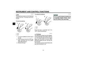
Fuel tank cap To open the fuel tank cap
Open the fuel tank cap lock cover, in-
sert the key into the lock, and then turn
it 1/4 turn clockwise. The lock will be re-
leased and the fuel tank cap can be
opened.
To close the fuel tank cap
1. Push the fuel tank cap into position
with the key inserted in the lock.
2. Turn the key counterclockwise to
the original position, remove it, and
then close the lock cover.
TIPThe fuel tank cap cannot be closed un-
less the key is in the lock. In addition,
the key cannot be removed if the cap is
not properly closed and locked.
WARNING
EWA11091
Make sure that the fuel tank cap is
properly closed after filling fuel.
Leaking fuel is a fire hazard.
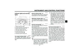
EAU13221
Fuel Make sure there is sufficient gasoline in
the tank.
WARNING
EWA10881
Gasoline and gasoline vapors are
extremely flammable. To avoid fires
and explosions and to reduce the
risk of injury when refueling, follow
these instructions.1. Before refueling, turn off the en-
gine and be sure that no one is sit-
ting on the vehicle. Never refuel
while smoking, or while in the vi-
cinity of sparks, open flames, or
other sources of ignition such as
the pilot lights of water heaters and
clothes dryers.
2. Do not overfill the fuel tank. When
refueling, be sure to insert the
pump nozzle into the fuel tank filler
hole. Stop filling when the fuel
reaches the bottom of the filler
tube. Because fuel expands when
it heats up, heat from the engine or
the sun can cause fuel to spill out
of the fuel tank.
1. Fuel tank cap lock cover
2. Unlock.
2
1
U11CE4E0.book Page 13 Friday, December 3, 2010 9:12 AM
Page 29 of 90

INSTRUMENT AND CONTROL FUNCTIONS
3-14
3
3. Wipe up any spilled fuel immedi-
ately. NOTICE: Immediately wipe
off spilled fuel with a clean, dry,
soft cloth, since fuel may deteri-
orate painted surfaces or plastic
parts.
[ECA10071]
4. Be sure to securely close the fuel
tank cap.
WARNING
EWA15151
Gasoline is poisonous and can
cause injury or death. Handle gaso-
line with care. Never siphon gaso-
line by mouth. If you should swallow
some gasoline or inhale a lot of gas-
oline vapor, or get some gasoline in
your eyes, see your doctor immedi-ately. If gasoline spills on your skin,
wash with soap and water. If gaso-
line spills on your clothing, change
your clothes.
EAU33502
NOTICE
ECA11400
Use only unleaded gasoline. The use
of leaded gasoline will cause severe
damage to internal engine parts,
such as the valves and piston rings,
as well as to the exhaust system.Your Yamaha engine has been de-
signed to use regular unleaded gaso-
line with a research octane number of
91 or higher. If knocking (or pinging) oc-
curs, use a gasoline of a different brandor premium unleaded fuel. Use of un-
leaded fuel will extend spark plug life
and reduce maintenance costs.
1. Fuel tank filler tube
2. Maximum fuel level1
2
Recommended fuel:
Regular unleaded gasoline only
Fuel tank capacity:
19.0 L (5.02 US gal, 4.18 Imp.gal)
Fuel reserve amount (when the fuel
level warning light comes on):
3.7 L (0.98 US gal, 0.81 Imp.gal)
U11CE4E0.book Page 14 Friday, December 3, 2010 9:12 AM
Page 30 of 90

INSTRUMENT AND CONTROL FUNCTIONS
3-15
3
EAU39451
Fuel tank breather/overflow
hose Before operating the motorcycle:�
Check the fuel tank breather/over-
flow hose connection.
�
Check the fuel tank breather/over-
flow hose for cracks or damage,
and replace it if damaged.
�
Make sure that the end of the fuel
tank breather/overflow hose is not
blocked, and clean it if necessary.
EAU13433
Catalytic converter This model is equipped with a catalytic
converter in the exhaust system.
WARNING
EWA10862
The exhaust system is hot after op-
eration. To prevent a fire hazard or
burns:�
Do not park the vehicle near
possible fire hazards such as
grass or other materials that
easily burn.
�
Park the vehicle in a place
where pedestrians or children
are not likely to touch the hot
exhaust system.
�
Make sure that the exhaust sys-
tem has cooled down before do-
ing any maintenance work.
�
Do not allow the engine to idle
more than a few minutes. Long
idling can cause a build-up of
heat.
NOTICE
ECA10701
Use only unleaded gasoline. The use
of leaded gasoline will cause unre-
pairable damage to the catalytic
converter.
1. Fuel tank overflow hose
2. Fuel tank breather hose
2 1
U11CE4E0.book Page 15 Friday, December 3, 2010 9:12 AM
Page 31 of 90

INSTRUMENT AND CONTROL FUNCTIONS
3-16
3
EAU42750
Rider seat To remove the rider seat
1. Insert the key into the seat lock,
and then turn it counterclockwise.
2. Lift the front of the seat up, and
then pull the seat off.
To install the rider seat
1. Insert the projection on the rear of
the seat into the seat holder as
shown.2. Push the front of the seat down to
lock it in place.
3. Remove the key.
TIPMake sure that the seat is properly se-
cured before riding.
EAU14324
Helmet holder The helmet holder is located under the
rider seat.
To secure a helmet to the helmet
holder
1. Remove the rider seat. (See the
previous section ŌĆ£Rider seatŌĆØ.)
2. Hook the helmet onto the helmet
holder, and then securely install
the seat. WARNING! Never ride
with a helmet attached to the
helmet holder, since the helmet
may hit objects, causing loss of
control and possibly an acci-
dent.
[EWA10161]
1. Seat lock
2. Unlock.
1. Projection
2. Seat holder
1
2
1. Helmet holder
1
U11CE4E0.book Page 16 Friday, December 3, 2010 9:12 AM
Page 32 of 90

INSTRUMENT AND CONTROL FUNCTIONS
3-17
3To release the helmet from the hel-
met holder
Remove the rider seat, remove the hel-
met from the helmet holder, and then
install the seat.
EAU42545
Adjusting the shock absorber
assembly This shock absorber assembly is
equipped with a spring preload adjust-
ing ring, allowing the spring preload to
be adjusted to suit the riderŌĆÖs prefer-
ence.
It is recommended to have a Yamaha
dealer adjust the spring preload.�
Should you choose to make the
adjustment, use the special
wrench included in the additional
tool kit, which was handed out sep-
arately at the purchase of the vehi-
cle.
NOTICE
ECA10101
To avoid damaging the mechanism,
do not attempt to turn beyond the
maximum or minimum settings.Adjust the spring preload as follows.
To increase the spring preload and
thereby harden the suspension, turn
the adjusting ring in direction (a). To de-
crease the spring preload and thereby
soften the suspension, turn the adjust-
ing ring in direction (b).
TIPAlign the appropriate notch in the ad-
justing ring with the position indicator
on the shock absorber.1. Shock absorber assembly
2. Position indicator
3. Spring preload adjusting ringSpring preload setting:
Minimum (soft):
1
Standard:
4
Maximum (hard):
9
U11CE4E0.book Page 17 Friday, December 3, 2010 9:12 AM