Page 57 of 84

PERIODIC MAINTENANCE AND ADJUSTMENT
7-14
7
WARNING
EWA10461
The front and rear tires should be of
the same make and design, other-
wise the handling characteristics of
the vehicle may be different, which
could lead to an accident.After extensive tests, only the tires list-
ed below have been approved for this
model by Yamaha Motor Co., Ltd.
WARNING
EWA15541
�
Have a Yamaha dealer replace
excessively worn tires. Operat-
ing the motorcycle with exces-
sively worn tires decreases
riding stability and can lead to
loss of control.
�
The replacement of all wheel-
and brake-related parts, includ-
ing the tires, should be left to a
Yamaha dealer, who has the
necessary professional knowl-
edge and experience.
�
It is not recommended to patch
a punctured tube. If unavoid-
able, however, patch the tube
very carefully and replace it as
soon as possible with a high-
quality product.
�
Ride conservatively after
changing a tire since the tire
must seat itself on the rim prop-
erly. Failure to allow proper
seating may cause tire failure,
which may result in damage to
the motorcycle and injury to the
rider.
EAU21942
Spoke wheels
WARNING
EWA10610
The wheels on this model are not de-
signed for use with tubeless tires.
Do not attempt to use tubeless tires
on this model.To maximize the performance, durabil-
ity, and safe operation of your motorcy-
cle, note the following points regarding
the specified wheels.�
The wheel rims should be checked
for cracks, bends or warpage, and
the spokes for looseness or dam-
age before each ride. If any dam-
age is found, have a Yamaha
dealer replace the wheel. Do not
attempt even the smallest repair to
the wheel. A deformed or cracked
wheel must be replaced.
�
The wheel should be balanced
whenever either the tire or wheel
has been changed or replaced. An
unbalanced wheel can result in
poor performance, adverse han-
dling characteristics, and a short-
ened tire life.
Front tire:
Size:
2.50-10 4PR
Manufacturer/model:
CHENG SHIN/KNOBBY
Rear tire:
Size:
2.50-10 4PR
Manufacturer/model:
CHENG SHIN/KNOBBY
U1P685E0.book Page 14 Tuesday, April 20, 2010 3:18 PM
Page 58 of 84

PERIODIC MAINTENANCE AND ADJUSTMENT
7-15
7
EAU46251
Adjusting the clutch free play The clutch free play must be checked
and, if necessary, adjusted as follows
at the intervals specified in the periodic
maintenance and lubrication chart.
1. Remove the clutch adjusting
screw cover by removing the
screws.
2. Loosen the locknut.
3. Slowly turn the clutch adjusting
screw in direction (a) until resis-
tance is felt, and then turn it 1/8
turn in direction (b).4. Tighten the locknut to the specified
torque.
TIPWhen tightening the locknut, hold the
clutch adjusting screw with a screwdriv-
er so that it does not turn together with
the locknut.5. Install the clutch adjusting screw
cover by installing the screws.
EAU22130
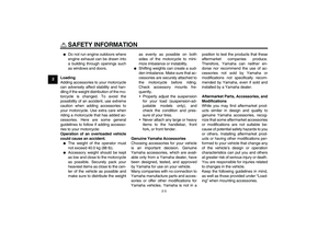
Adjusting the brake lever free
play The brake lever free play should mea-
sure 10.0–20.0 mm (0.39–0.79 in) as
shown. Periodically check the brake le-
ver free play and, if necessary, adjust it
as follows.
To increase the brake lever free play,
turn the adjusting nut at the brake shoe
plate in direction (a). To decrease the
brake lever free play, turn the adjusting
nut in direction (b).
1. Screw
2. Clutch adjusting screw cover
1. Locknut
2. Clutch adjusting screwTightening torque:
Locknut:
6 Nm (0.6 m·kgf, 4.3 ft·lbf)
1. Brake lever free play
1
U1P685E0.book Page 15 Tuesday, April 20, 2010 3:18 PM
Page 59 of 84

PERIODIC MAINTENANCE AND ADJUSTMENT
7-16
7
WARNING
EWA10650
If proper adjustment cannot be ob-
tained as described, have a Yamaha
dealer make this adjustment.
EAU44670
Adjusting the brake pedal free
play The brake pedal free play should mea-
sure 10.0–20.0 mm (0.39–0.79 in) at
the brake pedal end as shown. Period-
ically check the brake pedal free play
and, if necessary, adjust it as follows.
To increase the brake pedal free play,
turn the adjusting nut at the brake rod in
direction (a). To decrease the brake
pedal free play, turn the adjusting nut in
direction (b).
WARNING
EWA14820
�
After adjusting the drive chain
slack or removing and installing
the rear wheel, always check the
brake pedal free play.
�
If proper adjustment cannot be
obtained as described, have a
Yamaha dealer make this ad-
justment.
1. Brake lever free play adjusting nut
1
(a)
(b)
1. Brake pedal free play
1
1. Brake pedal free play adjusting nut
(b) (a)
1
U1P685E0.book Page 16 Tuesday, April 20, 2010 3:18 PM
Page 60 of 84
PERIODIC MAINTENANCE AND ADJUSTMENT
7-17
7
EAU44820
Checking the shift pedal The operation of the shift pedal should
be checked before each ride. If opera-
tion is not smooth, have a Yamaha
dealer check the vehicle.
EAU22361
Checking the front and rear
brake shoes Front
RearThe front and rear brake shoes must be
checked for wear at the intervals spec-
ified in the periodic maintenance and
lubrication chart. Each brake is provid-
ed with a wear indicator, which allows
you to check the brake shoe wear with-
out having to disassemble the brake.
To check the brake shoe wear, check
the position of the wear indicator while
applying the brake. If a brake shoe has
worn to the point that the wear indicator
reaches the wear limit line, have a
Yamaha dealer replace the brake
shoes as a set.1. Brake shoe wear indicator
2. Brake shoe wear limit line
1. Brake shoe wear indicator
2. Brake shoe wear limit line
2
1
21
U1P685E0.book Page 17 Tuesday, April 20, 2010 3:18 PM
Page 61 of 84

PERIODIC MAINTENANCE AND ADJUSTMENT
7-18
7
EAU22760
Drive chain slack The drive chain slack should be
checked before each ride and adjusted
if necessary.
EAU22773
To check the drive chain slack
1. Place the motorcycle on the side-
stand.TIPWhen checking and adjusting the drive
chain slack, there should be no weight
on the motorcycle.2. Shift the transmission into the neu-
tral position.
3. Move the rear wheel by pushing
the motorcycle to locate the tight-
est portion of the drive chain, and
then measure the drive chain slack
as shown.4. If the drive chain slack is incorrect,
adjust it as follows.
EAU40112
To adjust the drive chain slack
1. Loosen the brake pedal free play
adjusting nut, axle nut, and locknut
at each end of the swingarm.
2. To tighten the drive chain, turn the
drive chain slack adjusting nut at
each end of the swingarm in direc-
Drive chain slack:
35.0–45.0 mm (1.38–1.77 in)
1. Drive chain slack
1. Brake pedal free play adjusting nut
2. Drive chain slack adjusting nut
3. Locknut
1. Axle nut
2. Drive chain slack adjusting nut
3. Locknut
1
2
3
2
3
1
U1P685E0.book Page 18 Tuesday, April 20, 2010 3:18 PM
Page 62 of 84
. To loosen the drive chain,
turn the adjusting nut at each end
of the swingarm in direction (b),
and then push the rear wheel for-
ward. NOTICE: Impr")
PERIODIC MAINTENANCE AND ADJUSTMENT
7-19
7tion (a). To loosen the drive chain,
turn the adjusting nut at each end
of the swingarm in direction (b),
and then push the rear wheel for-
ward. NOTICE: Improper drive
chain slack will overload the en-
gine as well as other vital parts
of the motorcycle and can lead
to chain slippage or breakage.
To prevent this from occurring,
keep the drive chain slack with-
in the specified limits.
[ECA10571]
TIPUsing the alignment marks on each
side of the swingarm, make sure that
both drive chain pullers are in the same
position for proper wheel alignment.
3. Tighten both locknuts and the axle
nut to the specified torques.
4. Adjust the brake pedal free play.
(See page 7-16.)
EAU23016
Cleaning and lubricating the
drive chain The drive chain must be cleaned and
lubricated at the intervals specified in
the periodic maintenance and lubrica-
tion chart, otherwise it will quickly wear
out, especially when riding in dusty or
wet areas. Service the drive chain as
follows.NOTICE
ECA10583
The drive chain must be lubricated
after washing the motorcycle, riding
in the rain or riding in wet areas.1. Remove all dirt and mud from the
drive chain with a brush or cloth.TIPFor a thorough cleaning, have a
Yamaha dealer remove the drive chain
and soak it in solvent.2. Spray Yamaha Chain and Cable
Lube or a high-quality spray-type
drive chain lubricant on the entire
chain, making sure that all side
plates and rollers have been suffi-
ciently oiled.
1. Alignment marks
2. Drive chain puller
3. Drive chain slack adjusting nutTightening torques:
Locknut:
7 Nm (0.7 m·kgf, 5.1 ft·lbf)
Axle nut:
60 Nm (6.0 m·kgf, 43 ft·lbf)
(b)(a)3
2
1
U1P685E0.book Page 19 Tuesday, April 20, 2010 3:18 PM
Page 63 of 84

PERIODIC MAINTENANCE AND ADJUSTMENT
7-20
7
EAU23093
Checking and lubricating the
cables The operation of all control cables and
the condition of the cables should be
checked before each ride, and the ca-
bles and cable ends should be lubricat-
ed if necessary. If a cable is damaged
or does not move smoothly, have a
Yamaha dealer check or replace it.
WARNING! Damage to the outer
housing of cables may result in in-
ternal rusting and cause interfer-
ence with cable movement. Replace
damaged cables as soon as possi-
ble to prevent unsafe conditions.[EWA10711]EAU23113
Checking and lubricating the
throttle grip and cable The operation of the throttle grip should
be checked before each ride. In addi-
tion, the cable should be lubricated by a
Yamaha dealer at the intervals speci-
fied in the periodic maintenance chart.
The throttle cable is equipped with a
rubber boot. Make sure that the boot is
securely installed. Even though the
boot is installed correctly, it does not
completely protect the cable from water
entry. Therefore, use care not to pour
water directly onto the boot or cable
when washing the vehicle. If the cable
or boot becomes dirty, wipe clean with
a moist cloth.
EAU43622
Checking and lubricating the
brake lever The operation of the brake lever should
be checked before each ride, and the
lever pivot should be lubricated if nec-
essary.
Recommended lubricant:
Yamaha Chain and Cable Lube or
engine oil
Recommended lubricant:
Lithium-soap-based grease
U1P685E0.book Page 20 Tuesday, April 20, 2010 3:18 PM
Page 64 of 84

PERIODIC MAINTENANCE AND ADJUSTMENT
7-21
7
EAU23182
Checking and lubricating the
brake pedal The operation of the brake pedal
should be checked before each ride,
and the pedal pivot should be lubricat-
ed if necessary.
EAU23202
Checking and lubricating the
sidestand The operation of the sidestand should
be checked before each ride, and the
sidestand pivot and metal-to-metal
contact surfaces should be lubricated if
necessary.
WARNING
EWA10731
If the sidestand does not move up
and down smoothly, have a Yamaha
dealer check or repair it. Otherwise,
the sidestand could contact the
ground and distract the operator, re-
sulting in a possible loss of control.
EAUM1651
Lubricating the swingarm piv-
ots The swingarm pivots must be lubricat-
ed by a Yamaha dealer at the intervals
specified in the periodic maintenance
and lubrication chart.
Recommended lubricant:
Lithium-soap-based grease
Recommended lubricant:
Lithium-soap-based grease
Recommended lubricant:
Lithium-soap-based grease
U1P685E0.book Page 21 Tuesday, April 20, 2010 3:18 PM