Page 25 of 84

SAFETY INFORMATION
2-4
2
�
Never install accessories that
would impair the performance of
your motorcycle. Carefully inspect
the accessory before using it to
make sure that it does not in any
way reduce ground clearance or
cornering clearance, limit suspen-
sion travel, steering travel or con-
trol operation.
Accessories fitted to the handle-
bar or the front fork area can
create instability due to improper
weight distribution. If accesso-
ries are added to the handlebar
or front fork area, they must be
as lightweight as possible and
should be kept to a minimum.
Bulky or large accessories may
seriously affect the stability of
the motorcycle. Wind may at-
tempt to lift the motorcycle, or
the motorcycle may become un-
stable in cross winds.
Certain accessories can dis-
place the operator from his or
her normal riding position. This
improper position limits the free-
dom of movement of the opera-tor and may limit control ability,
therefore, such accessories are
not recommended.
�
Use caution when adding electri-
cal accessories. If electrical acces-
sories exceed the capacity of the
motorcycle’s electrical system, an
electric failure could result, which
could cause a dangerous loss of
lights or engine power.
Aftermarket Tires and Rims
The tires and rims that came with your
motorcycle were designed to match the
performance capabilities and to provide
the best combination of handling, brak-
ing, and comfort. Other tires, rims, siz-
es, and combinations may not be
appropriate. Refer to page 7-13 for tire
specifications and more information on
replacing your tires.
Transporting the Motorcycle
Be sure to observe following instruc-
tions before transporting the motorcy-
cle in another vehicle.
�
Remove all loose items from the
motorcycle.
�
Check that the fuel cock (if
equipped) is in the “OFF” position
and that there are no fuel leaks.
�
Point the front wheel straight
ahead on the trailer or in the truck
bed, and choke it in a rail to pre-
vent movement.
�
Shift the transmission in gear (for
models with a manual transmis-
sion).
�
Secure the motorcycle with tie-
downs or suitable straps that are
attached to solid parts of the mo-
torcycle, such as the frame or up-
per front fork triple clamp (and not,
for example, to rubber-mounted
handlebars or turn signals, or parts
that could break). Choose the lo-
cation for the straps carefully so
the straps will not rub against
painted surfaces during transport.
�
The suspension should be com-
pressed somewhat by the tie-
downs, if possible, so that the mo-
torcycle will not bounce excessive-
ly during transport.
U1P685E0.book Page 4 Tuesday, April 20, 2010 3:18 PM
Page 26 of 84
DESCRIPTION
3-1
3
EAU10410
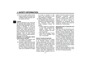
Left view
12 34 5
76
1. Fuel cock (page 4-6)
2. Throttle stop screw (page 7-11)
3. Air filter element (page 7-8)
4. Fuse (page 7-25)
5. Battery (page 7-23)
6. Engine oil drain bolt (page 7-7)
7. Shift pedal (page 4-3)U1P685E0.book Page 1 Tuesday, April 20, 2010 3:18 PM
Page 27 of 84
DESCRIPTION
3-2
3
EAU10420
Right view
4 65 32 1
1. Seat (page 4-7)
2. Fuel tank cap (page 4-4)
3. Spark plug cap (page 7-6)
4. Brake pedal (page 4-3)
5. Clutch adjusting screw (page 7-15)
6. Engine oil filler cap (page 7-7)
U1P685E0.book Page 2 Tuesday, April 20, 2010 3:18 PM
Page 28 of 84
DESCRIPTION
3-3
3
EAU10430
Controls and instruments
14
5 2
6 3
1. Engine stop switch (page 4-1)
2. Starter (choke) lever (page 4-7)
3. Main switch (page 4-1)
4. Brake lever (page 4-3)
5. Throttle grip (page 7-12)
6. Start switch (page 4-1)U1P685E0.book Page 3 Tuesday, April 20, 2010 3:18 PM
Page 29 of 84
INSTRUMENT AND CONTROL FUNCTIONS
4-1
4
EAU40340
Main switch The main switch controls the ignition
system. The main switch positions are
described below.
EAU10630
ON
All electrical systems are supplied with
power, and the engine can be started.
The key cannot be removed.
EAU45751
OFF
All electrical systems are off. The key
can be removed.
WARNING
EWA10072
Never turn the key to “OFF” while
the vehicle is moving, otherwise the
electrical systems will be switched
off, which may result in loss of con-
trol or an accident.
EAU12348
Handlebar switches Left
Right1. Engine stop switch“/”
1. Start switch“”
1
U1P685E0.book Page 1 Tuesday, April 20, 2010 3:18 PM
Page 30 of 84

INSTRUMENT AND CONTROL FUNCTIONS
4-2
4
EAU12660
Engine stop switch“/”
Set this switch to“” before starting
the engine. Set this switch to“” to
stop the engine in case of an emergen-
cy, such as when the vehicle overturns
or when the throttle cable is stuck.
EAU12711
Start switch“”
Push this switch to crank the engine
with the starter. See page 6-1 for start-
ing instructions prior to starting the en-
gine.
EAU39862
Speed limiter Your motorcycle is equipped with an
adjustable speed limiter. The speed
limiter keeps the throttle from fully
opening, even when the throttle grip is
turned to the maximum.
1. Loosen the locknut.
2. To increase the maximum engine
power available and the maximum
speed of the motorcycle, turn the
adjusting screw in direction (a). To
decrease the maximum engine
power available and the maximum
speed of the motorcycle, turn the
adjusting screw in direction (b).
3. Tighten the locknut.
WARNING
EWA14401
Improper adjustment of the speed
limiter could cause improper throttle
operation. You could lose control,
have an accident or be injured. Do
not turn the adjusting screw out
more than 25 mm (0.98 in). Always
make sure the throttle cable free
play is adjusted to 3.0–5.0 mm (0.12–
0.20 in). (See page 7-12.)
1. Locknut
2. Adjusting screw
12
(b)
(a)
1. No more than 25 mm (0.98 in)
1
U1P685E0.book Page 2 Tuesday, April 20, 2010 3:18 PM
Page 31 of 84
INSTRUMENT AND CONTROL FUNCTIONS
4-3
4
EAU39851
Shift pedal This motorcycle is equipped with a con-
stant-mesh 3-speed transmission. The
shift pedal is located on the left side of
the motorcycle. Neutral is at the bottom
position.
EAU12890
Brake lever The brake lever is located at the right
handlebar grip. To apply the front
brake, pull the lever toward the handle-
bar grip.
EAU12941
Brake pedal The brake pedal is on the right side of
the motorcycle. To apply the rear
brake, press down on the brake pedal.
1. Shift pedal
1. Brake lever
1
1. Brake pedal
1
U1P685E0.book Page 3 Tuesday, April 20, 2010 3:18 PM
Page 32 of 84

INSTRUMENT AND CONTROL FUNCTIONS
4-4
4
EAU13182
Fuel tank cap To remove the fuel tank cap, turn it
counterclockwise, and then pull it off.
To install the fuel tank cap, insert it into
the tank opening, and then turn it clock-
wise.
WARNING
EWA11091
Make sure that the fuel tank cap is
properly closed after filling fuel.
Leaking fuel is a fire hazard.
EAU13212
Fuel Make sure there is sufficient gasoline in
the tank.
WARNING
EWA10881
Gasoline and gasoline vapors are
extremely flammable. To avoid fires
and explosions and to reduce the
risk of injury when refueling, follow
these instructions.1. Before refueling, turn off the en-
gine and be sure that no one is sit-
ting on the vehicle. Never refuel
while smoking, or while in the vi-
cinity of sparks, open flames, or
other sources of ignition such as
the pilot lights of water heaters and
clothes dryers.
2. Do not overfill the fuel tank. Stop
filling when the fuel reaches the
bottom of the filler tube. Because
fuel expands when it heats up,
heat from the engine or the sun
can cause fuel to spill out of the
fuel tank.3. Wipe up any spilled fuel immedi-
ately. NOTICE: Immediately wipe
off spilled fuel with a clean, dry,
soft cloth, since fuel may deteri-
orate painted surfaces or plastic
parts.
[ECA10071]
4. Be sure to securely close the fuel
tank cap.
WARNING
EWA15151
Gasoline is poisonous and can
cause injury or death. Handle gaso-
line with care. Never siphon gaso-
line by mouth. If you should swallow
some gasoline or inhale a lot of gas-
oline vapor, or get some gasoline in
your eyes, see your doctor immedi-
1. Fuel tank cap
1
1. Fuel tank filler tube
2. Maximum fuel level
U1P685E0.book Page 4 Tuesday, April 20, 2010 3:18 PM


2. Throttle stop screw (page 7-11)
3. Air filter element (page 7-8)
4. Fuse (page 7-25)
5. Battery (page 7-23)
6. Engine oil dra")

2. Fuel tank cap (page 4-4)
3. Spark plug cap (page 7-6)
4. Brake pedal (page 4-3)
5. Clutch adjusting screw (page 7-15)
6. Engine oi")

2. Starter (choke) lever (page 4-7)
3. Main switch (page 4-1)
4. Brake lever (page 4-3)
5. Throttle grip")

