Page 8 of 140

EBU17420
TABLE OF CONTENTS
LOCATION OF THE WARNING AND
SPECIFICATION LABELS ............................ 1-1
SAFETY INFORMATION .............................. 2-1
DESCRIPTION .............................................. 3-1
Left view ...................................................... 3-1
Right view.................................................... 3-1
Controls and instruments ............................ 3-2
INSTRUMENT AND CONTROL
FUNCTIONS .................................................. 4-1
Main switch ................................................ 4-1
Indicator lights ............................................ 4-2
Handlebar switches .................................... 4-2
Throttle lever .............................................. 4-3
Speed limiter .............................................. 4-4
Front brake lever ........................................ 4-4
Brake pedal and rear brake lever ............... 4-5
Parking brake ............................................. 4-6
Shift pedal .................................................. 4-6
Drive select lever ........................................ 4-7
Recoil starter .............................................. 4-7
Fuel tank cap .............................................. 4-7Fuel .............................................................4-8
Fuel cock ....................................................4-9
Starter (choke) ..........................................4-11
Seat ..........................................................4-11
Storage compartment ...............................4-12
Front carrier ..............................................4-13
Rear carrier ...............................................4-13
Adjusting the rear shock absorber
assembly .................................................4-14
PRE-OPERATION CHECKS ..........................5-1
Fuel .............................................................5-3
Engine oil ....................................................5-3
Final gear oil ...............................................5-3
Front and rear brakes .................................5-3
Throttle lever ...............................................5-4
Tires ............................................................5-4
Chassis fasteners .......................................5-6
Instruments, lights and switches .................5-6
Battery ........................................................5-6
OPERATION...................................................6-1
Starting a cold engine .................................6-1
Starting a warm engine ...............................6-3U1P066E0.book Page 1 Thursday, August 5, 2010 4:15 PM
Page 24 of 140
3-1
3
EBU17680
DESCRIPTION
EBU17690Left view
EBU17700Right view
1. Headlights
2. Fuel cock
3. Recoil starter
4. Fuses
5. Battery
6. Tail/brake light
7. Rear shock absorber assembly spring preload adjusting
ring
8. Engine oil drain bolt
9. Shift pedal
9
1. Spark arrester
2. Storage compartment and tool kit
3. Air filter case
4. Engine oil filler cap
5. Brake pedal
6. Clutch adjusting screw
7. Oil filter element
8. Rear brake light switch
5
1234
6 7 8
U1P066E0.book Page 1 Thursday, August 5, 2010 4:15 PM
Page 26 of 140
4-1
4
EBU17733
INSTRUMENT AND CONTROL FUNCTIONS
EBU17760Main switch The positions of the main switch are as follows:
ON
All electrical systems are supplied with power. The
headlights and taillight come on when the light
switch is on, and the engine can be started. The
key cannot be removed.
OFF
All electrical systems are off. The key can be re-
moved.
1. Main switch
OFF ON
1
U1P066E0.book Page 1 Thursday, August 5, 2010 4:15 PM
Page 27 of 140
4-2
4
EBU17793Indicator lights EBU17860Neutral indicator light“”
This indicator light comes on when the transmis-
sion is in the neutral position.EBU17830Reverse indicator light“”
This indicator light comes on when the transmis-
sion is in the reverse position.
EBU18061Handlebar switches EBU18080Engine stop switch“/”
Set this switch to“” before starting the engine.
The engine stop switch controls the ignition and
stops the engine when it is running. Use this switch
to stop the engine in an emergency situation. The
engine will not start or run when this switch is set
to“”.
1. Neutral indicator light “N”
2. Reverse indicator light “R”
1. Light switch“//OFF”
2. Engine stop switch“/”
3. Start switch“”
4. Horn switch“”
U1P066E0.book Page 2 Thursday, August 5, 2010 4:15 PM
Page 28 of 140

4-3
4
EBU18101Start switch“”
Push this switch to crank the engine with the start-
er. See the starting instructions on page 6-1 prior
to starting the engine.EBU18152Light switch“//OFF”
Set this switch to“” to turn on the low beams
and the taillight. Set the switch to“” to turn on
the high beams and the taillight. Set the switch to
“OFF” to turn off all the lights.NOTICEECB00041Do not use the headlights with the engine
turned off for an extended period of time, oth-
erwise the battery may discharge to the point
that the starter motor will not operate properly.
If this should happen, remove the battery and
recharge it. See page 8-39 for battery charging
information.EBU18170Horn switch“”
Press the switch to sound the horn.
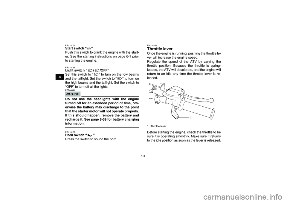
EBU18282Throttle lever Once the engine is running, pushing the throttle le-
ver will increase the engine speed.
Regulate the speed of the ATV by varying the
throttle position. Because the throttle is spring-
loaded, the ATV will decelerate, and the engine will
return to an idle any time the throttle lever is re-
leased.
Before starting the engine, check the throttle to be
sure it is operating smoothly. Make sure it returns
to the idle position as soon as the lever is released.1. Throttle lever
U1P066E0.book Page 3 Thursday, August 5, 2010 4:15 PM
Page 33 of 140
4-8
4
EBU18754Fuel Make sure there is sufficient gasoline in the tank.
WARNING
EWB02521Gasoline and gasoline vapors are extremely
flammable. To avoid fires and explosions and
to reduce the risk of injury when refueling, fol-
low these instructions.1. Before refueling, turn off the engine and be
sure that no one is sitting on the vehicle. Nev-
er refuel while smoking, or while in the vicinityof sparks, open flames, or other sources of ig-
nition such as the pilot lights of water heaters
and clothes dryers.
2. Do not overfill the fuel tank. When refueling,
be sure to insert the pump nozzle into the fuel
tank filler hole. Stop filling when the fuel reach-
es the bottom of the filler tube. Because fuel
expands when it heats up, heat from the en-
gine or the sun can cause fuel to spill out of
the fuel tank.1. Fuel tank cap
1. Fuel tank filler tube
2. Maximum fuel level
U1P066E0.book Page 8 Thursday, August 5, 2010 4:15 PM
Page 42 of 140

5-2
5
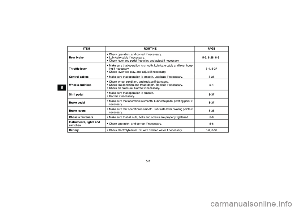
Rear brakeCheck operation, and correct if necessary.
Lubricate cable if necessary.
Check lever and pedal free play, and adjust if necessary.5-3, 8-28, 8-31
Throttle leverMake sure that operation is smooth. Lubricate cable and lever hous-
ing if necessary.
Check lever free play, and adjust if necessary.5-4, 8-27
Control cablesMake sure that operation is smooth. Lubricate if necessary. 8-35
Wheels and tiresCheck wheel condition, and replace if damaged.
Check tire condition and tread depth. Replace if necessary.
Check air pressure. Correct if necessary.5-4
Shift pedalMake sure that operation is smooth.
Correct if necessary.8-37
Brake pedal Make sure that operation is smooth. Lubricate pedal pivoting point if
necessary.8-37
Brake leversMake sure that operation is smooth. Lubricate lever pivoting points if
necessary.8-36
Chassis fastenersMake sure that all nuts, bolts and screws are properly tightened. 5-6
Instruments, lights and
switchesCheck operation, and correct if necessary. 5-6
BatteryCheck electrolyte level. Fill with distilled water if necessary. 5-6, 8-39 ITEM ROUTINE PAGEU1P066E0.book Page 2 Thursday, August 5, 2010 4:15 PM
Page 46 of 140
5-6
5
Aftermarket tires and rims
The tires and rims that came with your ATV were
designed to match the performance capabilities
and to provide the best combination of handling,
braking, and comfort. Other tires, rims, sizes, and
combinations may not be appropriate.
EBU19840Chassis fasteners Make sure that all nuts, bolts and screws are prop-
erly tightened.EBU19850Instruments, lights and switches Check that all instruments, lights and switches are
working properly. Correct if necessary.EBU19860Battery Check the fluid level in the battery. Fill with distilled
water if necessary. (See page 8-39.) Front:
Manufacturer/model:
YFM250A CARLISLE/TRAIL WOLF
YFM25BA MAXXIS/M905
Size:
AT22 x 7.00-10
Ty p e :
Tu b e l e s s
Rear:
Manufacturer/model:
YFM250A CARLISLE/TRAIL WOLF
YFM25BA MAXXIS/M906
Size:
AT22 x 10.00-10
Ty p e :
Tu b e l e s s
U1P066E0.book Page 6 Thursday, August 5, 2010 4:15 PM