Page 307 of 388

08 Maintenance and service
Engine compartment
08
��
307
Turn the handle about 20-25 degrees
clockwise. You will hear when the catch
releases.
Move the catch to the left and open the
bonnet. (The catch hook is located
between the headlamp and grille, see illus-
tration.)
WARNING
Check that the bonnet locks properly when
closed.
Engine compartment, overview
The appearance of the engine compartment may
vary depending on engine variant.
Coolant expansion tank
Power steering fluid reservoir
Engine oil dipstick1
Radiator
Filler opening for engine oil
Brake and clutch fluid reservoir (left-hand
drive)
Battery
Relay and fuse box, engine compartment
Filling washer fluid
Air filter
WARNING
High voltage from the ignition system. The
voltage in the ignition system is highly dan-
gerous. The remote control key must always
be in 0 position when work is being done in
the engine compartment, see page 81.
Do not touch the spark plugs or ignition coil
when the remote control key is in II position
or when the engine is hot.
Checking the engine oil
Volvo recommends Castrol oil products.
1Engines with electronic oil level sensor have no dipstick (5-cyl. diesel).
ProCarManuals.com
Page 310 of 388

08 Maintenance and service
Engine compartment
08
310
NOTE
The oil level is only detected by the system
during driving. The system cannot directly
detect changes when the oil is filled or
drained. The car must be driven
about 30 km before the oil level display is
correct.
WARNING
Do not fill more oil if filling level (3) or (4)
appears as shown in the illustration below.
The level must never be above MAX or
below MIN, as this could lead to engine
damage.
WARNING
Do not spill oil onto the hot exhaust manifold
due to the risk of fire.
Measuring the oil levelIf the oil level needs to be checked then it
should be carried out in accordance with the
sequence below.
1.
Activate key position II, see page 81.
2. Rotate the thumbwheel on the left-hand
stalk switch to position
Engine oil level
Wait....> You will then see information displayed
about the engine oil level.
The figures 1-4 represent filling level. Do not fill
more oil if filling level (3) or (4) is shown. Recom-
mended filling level is 4.
Coolant
Checking the level and topping up
When topping up the coolant, follow the
instructions on the packaging. It is important
that the mixture of coolant concentrate and
water is correct for the prevailing weather con-
ditions. Never top up with water only. The risk
of freezing increases with both too little and too
much coolant concentrate. For capacities, see
page 352.
ProCarManuals.com
Page 313 of 388

08 Maintenance and service
Lamps
08
��
313 General
All bulbs are specified, see page 317. Bulbs
and spotlights that are of a special type or that
are only suitable for replacement by a work-
shop are:
•General interior lighting in the roof, reading
lamps
•Glovebox lighting
•Courtesy lighting
•Direction indicators, door mirror
•Approach lighting
•Brake light
•Rear side position lamps, position lamps
•Xenon, Active Xenon lamps
•LED lamps, general
WARNING
On cars equipped with Xenon lamps, head-
lamp replacement must be performed at a
workshop - an authorised Volvo workshop
is recommended. The lamp must be han-
dled with extreme caution because it is
equipped with a high voltage unit.
IMPORTANT
Never touch the glass part of the bulbs with
your fingers. Grease and oils from your fin-
gers are vaporised by the heat, coating the
reflector and then causing damage.
Headlamps front
All of the headlamp bulbs are replaced via the
engine compartment. Loosen and remove the
whole headlamp.
WARNING
Always switch off the ignition and remove
the remote control key before starting to
replace a bulb.
Removing the headlamp1.
Press the START-/STOP ENGINE button
quickly.
2. (Upper illustration)
Pull out the headlamp's locking pins.
Release the headlamp by alternately
tilting and pulling it out.
ProCarManuals.com
Page 314 of 388

Detach the headlamp connector by
pressing down the clip with your th")
08 Maintenance and service
Lamps
08
314
IMPORTANT
Do not pull the electrical cable, only the con-
nector.
3. (Lower illustration)
Detach the headlamp connector by
pressing down the clip with your thumb.
At the same time, guide out the con-
nector with your other hand.
4. Lift out the headlamp and place it on a soft
surface to avoid scratching the lens.
5. Replace the bulb in question.
Securing the headlamp
1. Plug in the connector, a clicking sound
should be heard.2. Reinstall the headlamp and locking pins.
The short pin is fitted closest to the grille.
Check that they are correctly inserted.
3. Check the lighting.
The headlamp must be mounted and the con-
nector correctly installed before the lighting is
switched on or the remote control key is
inserted into the ignition switch.
Removing the cover
Before starting to replace a bulb, see
page 313.
1. Unscrew the cover's four screws with the
tool (1) in the tool kit, see page 288. They
should not be detached completely.
(3 - 4 turns are sufficient.)
IMPORTANT
Use the tool in the toolkit to remove and
attach this correctly.
2. Slide the cover to one side.
3. Remove the cover.
Reinstall the cover in reverse order.
Dipped beam, halogen
1. Detach the headlamp, see page 313.
2. Remove the cover.
3. Unplug the connector from the bulb.
4. Detach the bulb by pulling it straight out.
ProCarManuals.com
Page 319 of 388
08 Maintenance and service
Wiper blades and washer fluid
08
��
319 Wiper blades
Service position
In order to change, clean or lift the wiper blades
(for scraping off ice from the windscreen) they
must be in service position.
1. Make sure that the driver's door is closed.
2. Insert the remote control key in the ignition
switch.
3. Set the remote control key in ignition posi-
tion II, see page 81.
4. Turn the remote control key to key position
0 and keep the remote control key in the
ignition switch.5. Move the right-hand stalk switch up for
about 1 second. The wipers then move to
standing straight up.
The wipers return to the starting position when
the car is started.
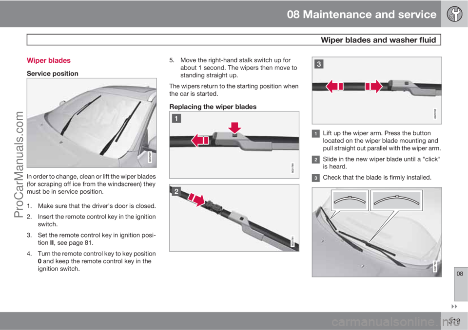
Replacing the wiper blades
Lift up the wiper arm. Press the button
located on the wiper blade mounting and
pull straight out parallel with the wiper arm.
Slide in the new wiper blade until a "click"
is heard.
Check that the blade is firmly installed.
G021763
ProCarManuals.com
Page 330 of 388
08 Maintenance and service
Fuses
08
330* Option/accessory, for more information, see Introduction.
Under the glovebox
Positions
Box
AFunctionA
Primary fuse for audio
control module*40
--
--
--
--
Box
AFunctionA
Door handle (Keyless*)5
--
Control panel, driver's
door20
Control panel, front pas-
senger door20
Box
AFunctionA
Control panel, rear pas-
senger door, right20
Control panel, rear pas-
senger door, left20
Keyless*7.5
Power seat driver's side*20
ProCarManuals.com
Page 332 of 388
08 Maintenance and service
Fuses
08
332* Option/accessory, for more information, see Introduction.
Box
BFunctionA
Remote control key
receiver, Movement detec-
tor alarm*, Climate panel5
Steering lock15
Siren alarm*, Data link con-
nector OBDII5
--
Airbags10
Collision warning system5
Accelerator pedal, PTC
element air preheater*,
Dimming, interior rearview
mirror*, Seat heating, rear*7.5
--
Brake light5
Sunroof*20
Immobiliser5
ProCarManuals.com
Page 361 of 388
09 Specifications
Type approval09
��
361 Remote control system
Country
A, B, CY,
CZ, D, DK,
E, EST, F,
FIN, GB,
GR, H, I,
IRL, L, LT,
LV, M, NL,
P, PL, S,
SK, SLO
Delphi hereby certifies
that this remote control key
system conforms to the
essential characteristic
requirements and other rele-
vant regulations of directive
1999/5/EC.
IS, LI, N, CH
HR
ROKDelphi 2003-07-15, Germany
R-LPD1-03-0151
Country
BR
RC
CCAB06LP1940T4
Radar system
Country
Singapore
IDA: Infocomm Development
Authority of Singapore.
Brazil
ProCarManuals.com