2011 VOLKSWAGEN TRANSPORTER battery
[x] Cancel search: batteryPage 186 of 486
Opening and closing the stowage compartment on the centre console
• To open the storage compartment@, slide the cover open.
• To close, push the cover shut, making sure that the storage compartment is closed completely
Ash tray
• Press the storage compartment@ in until it opens automatically. The ashtray is now accessible
• To empty the ashtray, press the button (8 in the storage compartment. The ashtray pops out of its holder. After emptying the ashtray, re-insert it.
Cigarette lighter
• Press the storage compartment@ in until it opens automatically.
• With the ignition switched on, press in the knob on the cigarette lighter.
• Wait for the lighter to pop out.
• Pull out the cigarette lighter and light the tobac-co product on the glowing spiral &.
• Insert the cigarette lighter back into the socket.
Opening and closing the stowage compartment at the front of the centre console
• To open, press the storage compartment@ in until it opens automatically.
• To close, push the storage compartment shut, making sure that it closes completely &.
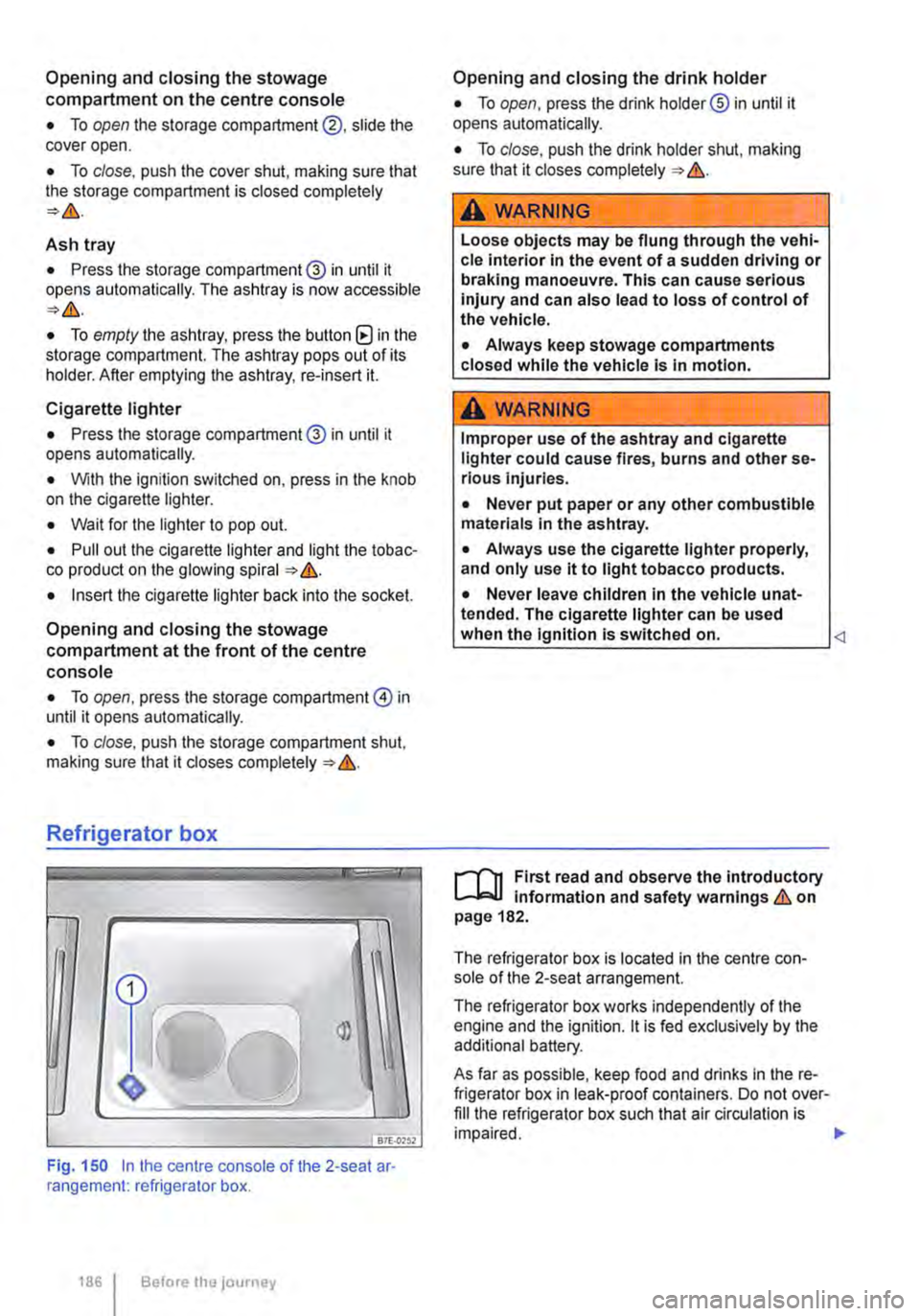
Refrigerator box
fBiU>,.,
Fig. 150 In the centre console of the 2-seat ar· rangement: refrigerator box.
1861 Before the journey
Opening and closing the drink holder
• To open, press the drink holder® in until it opens automatically.
• To close, push the drink holder shut, making sure that it closes completely &.
A WARNING
Loose objects may be flung through the vehi-cle interior In the event of a sudden driving or braking manoeuvre. This can cause serious injury and can also lead to loss of control of the vehicle.
• Always keep stowage compartments closed while the vehicle is in motion.
A WARNING
Improper use of the ashtray and cigarette lighter could cause fires, burns and other se-rious Injuries.
• Never put paper or any other combustible materials in the ashtray.
• Always use the cigarette lighter properly, and only use it to light tobacco products.
• Never leave children in the vehicle unat-tended. The cigarette lighter can be used when the Ignition is switched on.
The refrigerator box is located in the centre con-sole of the 2-seat arrangement.
The refrigerator box works independently of the engine and the ignition. lt is fed exclusively by the additional battery.
As far as possible, keep food and drinks in the re-frigerator box in leak-proof containers. Do not over-fill the refrigerator box such that air circulation is impaired. .,.
Page 187 of 486
Switching on the refrigerator box
• Slide the cover open =>Fig. 149 (D.
• Move switch =>Fig. 150 CD to I position. When the refrigerator box is switched on, the lamp in the box lights up.
• Fill the refrigerator box and then close the lid =>&.
Switching off the refrigerator box
• Slide the cover open =>Fig. 149 (D.
• Move switch =>Fig. 150 CD to 0 position. The in-dicator lamp in the refrigerator box goes out.
• Close the cover.
Notes on cleaning and care
Clean the refrigerator box thoroughly before using it for the first time, if it is dirty or if it has not been used for a long time.
To avoid stains and mildew in the refrigerator box if it remains unused for a long time, leave the cover slightly open.
• Use water and normal household cleaning fluid to clean the refrigerator box.
• The refrigerator box should be defrosted regu-larly to prevent layers of ice forming. To do this, switch the refrigerator box off and leave the cover open. Do not use an additional heat source to de-frost the refrigerator more quickly. This could dam-age the refrigerator =>
If the refrigerator box is left on when the engine is not running, the additional battery runs down. The refrigerator box is therefore fitted with a battery monitor. The battery monitor will switch the refriger-ated box off if the charge of the additional battery becomes too low. The battery monitor will switch the refrigerator box on again as soon as the addi-tional battery has reached a suitable charge level, for example, after a long journey.
Rear-seat telephony, Business
a:n Introduction
This chapter contains information on the following subjects:
Components . . . . . . . . . . . . . . . . . . . . . . . . . . . . 189
Pairing a mobile telephone before using it for the first time . . . . . . . . . 190
Functional description ........... . 190
A WARNING
Objects that are not secured, or are secured incorrectly, can cause serious injuries in the event of a sudden driving or braking manoeu-vre or accident.
• The refrigerator box lid must always be kept closed and locked when the vehicle is in motion.
• Never use the refrigerator box as a table or stowage compartment when the vehicle is In motion.
A WARNING
If the ambient temperature In the vehicle Is too low, the temperature in the refrigerator box could fall below +2 •c {+35 °F) degrees. ThIs could cause the contents of the refriger-ator box to freeze and bottles and other con-tainers to burst, potentially causing Injuries.
• Do not use the refrigerator box when the ambient temperature Is too low.
CD
Handling the refrigerator box incorrectly could damage it.
• Do not place containers, food or other ob-jects which are warmer than +50 •c (+122 •F) In the refrigerator box.
• Do not place corrosive substances or sol-vents in the refrigerator box.
• Do not use an additional heat source to de-frost the refrigerator box.
m The refrigerator box is not suitable for cooling W the vehicle interior. The refrigerator box should only be used to keep food cool and for transporting heat-sensitive items on short journeys.
The rear-seat telephony system (hands-free sys-tem in the passenger compartment with Private Mode) works independently of other provision for mobile telephones fitted in the vehicle. Neither the
Equipment, Business 1187
Page 192 of 486

Equipment, California
Vehicle overview, California
Fig. 153 View from above: overview of the interior equipment (left-hand drive)
The illustration shows optional equipment as well. Therefore, the equipment shown in the illustration may differ from the equipment which is fitted in the vehicle.
Key to Fig. 153:
CD Central control panel in the headliner . . . . . . . . . . . . . . . . . . . . . . . . . • . . . . . . . . . . . . . . . . . . . . 204
® Rotating front passenger seat . . . . . . . . . . . . . . . . . . . . . . . . . . . . . . . . . . . . . . . . . . . . . . . . . . . 69
@ Folding table in the sliding door . . . . . . . . . . . . . . . . . . . . . . . . . . . . . . . . . . . . . . . . . . . . . . 229
@ Work table . . . . . . . . . . . . . . . . . . . . . . . . . . . . . . . . . . . . . . . . . . . . . . . . . . . . . . . . . . . . . . . . . . 229
® Bench seaUbed with: . . . . . . . . . . . . . . . . . . . . . . . . . . . . . . . . . . . . . . . . . . . . . . . . . . . 195
-Holder for toolkit .......... .
-Breakdown set ..................................................... .
-Drawer ................................................................. · · ·
-Crank for awning .............................................•..............
® Adjustable mattress, ............................................•...............
0
®
Stowage compartment in the headliner with integrated loudspeakers ................... .
Rotating driver seat with: ........................................................ .
-12-volt fuses ..
-Additional battery ........... .
® 230-volt Euro socket in the side trim panel behind the left front seat ..
1921 Before the journey
416
425
212
226
197
214
69
249
248
242 ...
Page 193 of 486
@ Kitchen unit with:
-Gas cooker ................................... . 233
242
242
-230-volt grounded safety socket ................. .
-12-volt socket .............................•..................................
-Cupboard with two sliding doors
-Drawer
-Waste water tank with drain lever and opening for cleaning ...... . 237
-First aid kit on the rear panel of the left stowage compartment in the cupboard
@ Refrigerator box ...
@ Wardrobe with:
241
-Cleaning opening for fresh water tank . . . . . . . . . . . . . . . . . . . . . . . . . . . . . . . . . . . . . . . 237
-Second additional battery . . . . . ........ , . . . . . . . . . . . . . . . . . . . . . . . . . . 248
-Lockable stowage compartment . . . . . . . . . . . . . . . . . . . . . . . . . . . . . . . . . . . . . . . . . . . . . . . . 214
@ Stowage area with:
-Residual current circuit breaker ............... , ...... . 247
233
229
-Gas bottle holder .................. .
® Tailgate with room for stowing two camping chairs
Number of seats
The vehicle has a total of 4 seats: 2 at the front and 2 at the rear. Each seat is equipped with a seat belt.
Retrofitting seats
Additional seats can be retrofitted, provided that the maximum number of seats quoted by the man-ufacturer is not exceeded. For this purpose, seat anchor points should be fitted to the vehicle floor by a specialist workshop in accordance with Volks-wagen AG guidelines.
These additional seats must also have seat belt anchor points and suitable seat belts.
The Volkswagen Commercial Vehicles dealership can provide you with more information on retrofit-ting seats.
Furniture Catches
The flaps and doors are fitted with furniture catch-es to prevent them from opening when the vehicle is in motion.
Seat functions, rear, California
ClJ Introduction
This chapter contains information on the following subjects:
Bench seat/bed . . . . . . . . . . . . . . . . . . . . • • . . . 195
Bed (bench seat/bed) . . . . . . . . . . . 196 Mattress, bench seat/bed . . . . . . . . . . . . . . . . . 197
Components of the mattress, 3-seat bench . . 198
To open the doors in the kitchen unit, press and hold the catch. Slide the door open.
Equipment accessible only from the outside of the vehicle
• Opening for filling the fresh water tank on the rear left side of the vehicle (with lockable lid and separate key)
• 230-volt electrical feed on the rear left side of the vehicle (with flap cover)
• Fresh water tank drain opening under the vehi-cle.
• Waste water tank drain opening under the vehi-cle.
• Awning rails on the left and right side of the top of the vehicle on the roof frame.
• Awning adapter on left (if vehicle is fitted with an awning) and on right in the awning rail.
• Awning: attach to aluminium rail on right side over sliding door only.
Mattress for a medium-length bed, 3-seat bench . . . . . . . . . . . . . . . . . . . . . . . . . . . . 199 Mattress for a long bed, 3-seat bench . . . . . . . 201 Stowing the mattress, 3-seat bench . . . . . . . . 203 .,..
Equipment, California 1193
Page 205 of 486
Button, control
Display
®
Additional information =>Fig. 168.
To return to initial screen or cancel a setting without saving it
To completely switch off all functions which were activated using the central control panel, e.g. supplementary heating system, refrigerator box, and wake-up time <1
1 9.5 ° c
Fr f."l11 :28
0
Pj
3
0 117H-01S9
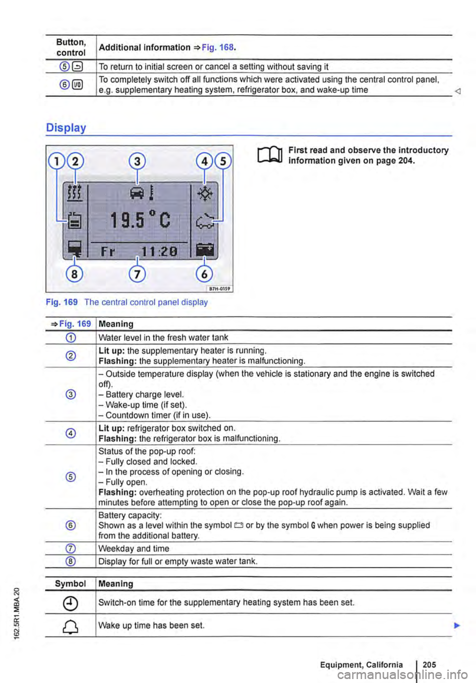
First read and observe the introductory lnfonmation given on page 204.
Fig. 169 The central control panel display
=>Fig. 169 Meaning
CD Water level in the fresh water tank
® Lit up: the supplementary heater is running. Flashing: the supplementary heater is malfunctioning.
-Outside temperature display (when the vehicle is stationary and the engine is switched
@ off). -Battery charge level. -Wake-up time (if set). -Countdown timer (if in use).
@ Lit up: refrigerator box switched on. Flashing: the refrigerator box is malfunctioning.
Status of the pop-up roof: -Fully closed and locked.
® -In the process of opening or closing. -Fully open. Flashing: overheating protection on the pop-up roof hydraulic pump is activated. Wait a few minutes before attempting to open or close the pop-up roof again.
Battery capacity:
® Shown as a level within the symbol o or by the symbol G when power is being supplied from the additional battery.
Symbol Meaning
Switch-on time for the supplementary heating system has been set.
Wake up time has been set.
Equipment, California 1205
Page 206 of 486
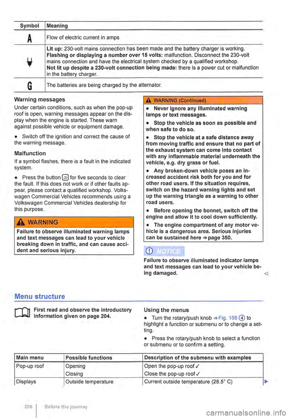
Symbol Meaning
A Flow of electric current in amps
Lit up: 230-volt mains connection has been made and the battery charger is working. Flashing or displaying a number over 15 volts: malfunction. Disconnect the 230-volt mains connection and have the electrical system checked by a qualified workshop. Not lit up despite a 230-volt connection being made: there is a power cut or malfunction in the battery charger.
G The batteries are being charged by the alternator.
Warning messages
Under certain conditions, such as when the pop-up roof is open, warning messages appear on the dis-play when the engine is started. These warn against possible vehicle or equipment damage.
• Switch off the ignition and correct the cause of the warning message.
Malfunction
If a symbol flashes, there is a fault in the indicated system.
• Press the button G?) for five seconds to clear the fault. If this does not work or if other faults ap-pear, please contact a qualified workshop. Volks-wagen Commercial Vehicles recommends using a Volkswagen Commercial Vehicles dealership for this purpose.
A WARNING
Failure to observe illuminated warning lamps and text messages can lead to your vehicle breaking down in traffic, and can cause acci-dent and serious injury.
A WARNING (Continued)
• Never Ignore any Illuminated warning lamps or text messages.
• Stop the vehicle as soon as possible and when safe to do so.
• Stop the vehicle at a safe distance away from moving traffic and ensure that no part of the exhaust system can come Into contact with any Inflammable material underneath the vehicle, e.g. dry grass or fuel.
• Any broken-down vehicle poses an In-creased accident risk both for you and for other road users. If the situation requires, switch on the hazard warning lights and set up the warning triangle as a warning to other road users.
• Before opening the bonnet, switch off the engine and allow it to cool down sufficiently.
• The engine compartment of any motor ve-hicle is a dangerous area. Serious injuries can be sustained here 350.
CD
Failure to observe illuminated indicator lamps and text messages can lead to your vehicle be-ing damaged.
J'"'""'('n First read and observe the introductory L-J,:.IJ information given on page 204.
Main menu Possible functions
Pop-up roof Opening
Closing
Displays Outside temperature
206 Before the journey
Using the menus
• Turn the rotary/push knob 168@ to highlight a function or submenu or to change a set-ting.
• Press the rotary/push knob to select a function or submenu or to confirm a setting.
Description of the submenu with examples
Open the pop-up roof .,1
Close the pop-up roof .,t
Current outside temperature (28.SO C) ...
Page 207 of 486
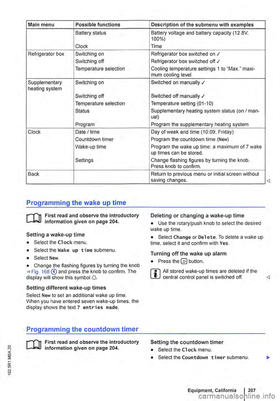
Main menu Possible functions
Battery status
Clock
Refrigerator box Switching on
Switching off
Temperature selection
Supplementary Switching on heating system
Switching off
Temperature selection
Status
Program
Clock Date I time
Countdown timer
Wake-up time
Settings
Back
Programming the wake up time
r--f"'n First read and observe the introductory L-lo::.U information given on page 204.
Setting a wake-up time
• Select the Clock menu.
• Select the Wake up time submenu.
• Select New.
• Change the flashing figures by turning the knob 168@ and press the knob to confirm. The display will show this symbol 0.
Setting different wake-up times
Select New to set an additional wake up time. When you have entered seven wake-up times, the display shows the text 7 entries made.
Programming the countdown timer
r--f"'n First read and observe the introductory L-lo::.U information given on page 204.
Description of the submenu with examples
Battery voltage and battery capacity (12.8V, 100%)
Time
Refrigerator box switched on .t
Refrigerator box switched off ./
Cooling temperature settings 1 to "Max." maxi-mum cooling level
Switched on manually .;
Switched off manually .;
Temperature setting (01-10)
Supplementary heating system status (on I man-ual)
Program the supplementary heating system
Day of week and time (10:09. Friday)
Program the countdown time (New)
Program the wake up time: a maximum of 7 wake up times can be stored.
Change flashing figures by turning the knob. Press knob to confirm.
Return to previous menu or initial screen without saving changes.
Deleting or changing a wake-up time
• Use the rotary/push knob to select the desired wake up time.
• Select Change or Del et e. To delete a wake up time, select it and confirm with Yes.
Turning off the wake up alarm
• Press button.
r::l All stored wake-up times are deleted if the L!J central control panel is switched off.
Setting the countdown timer
• Select the Clock menu.
• Select the Countdown timer submenu.
Equipment, California I 207
Page 208 of 486
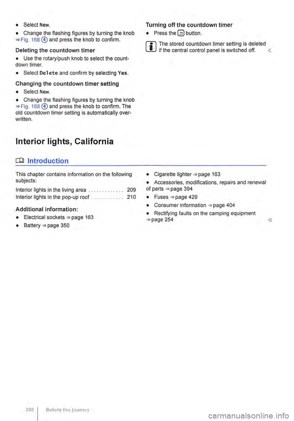
• Select New.
• Change the flashing figures by turning the knob 168 @) and press the knob to confirm.
Deleting the countdown timer
• Use the rotary/push knob to select the count-down timer.
• Select Delete and confirm by selecting Yes.
Changing the countdown timer setting
• Select New.
• Change the flashing figures by turning the knob 168@) and press the knob to confirm. The old countdown timer setting is automatically over-written.
Interior lights, California
CClJ Introduction
This chapter contains information on the following subjects:
Interior lights in the living area . . . . • . • . . . . . . 209
Interior lights in the pop-up roof . . . . . . . . . . . 210
Additional information:
• Electrical sockets 163
• Battery 350
208 Before the journey
Turning off the countdown timer
• Press the (2) button.
W The stored countdown timer setting is deleted L!J if the central control panel is switched off. <
• Cigarette lighter 163
• Accessories, modifications, repairs and renewal of parts 394
• Fuses 429
• Consumer information 404
• Rectifying faults on the camping equipment 254