2011 VOLKSWAGEN TRANSPORTER mirror
[x] Cancel search: mirrorPage 217 of 486

Opaque shades kit, integrated
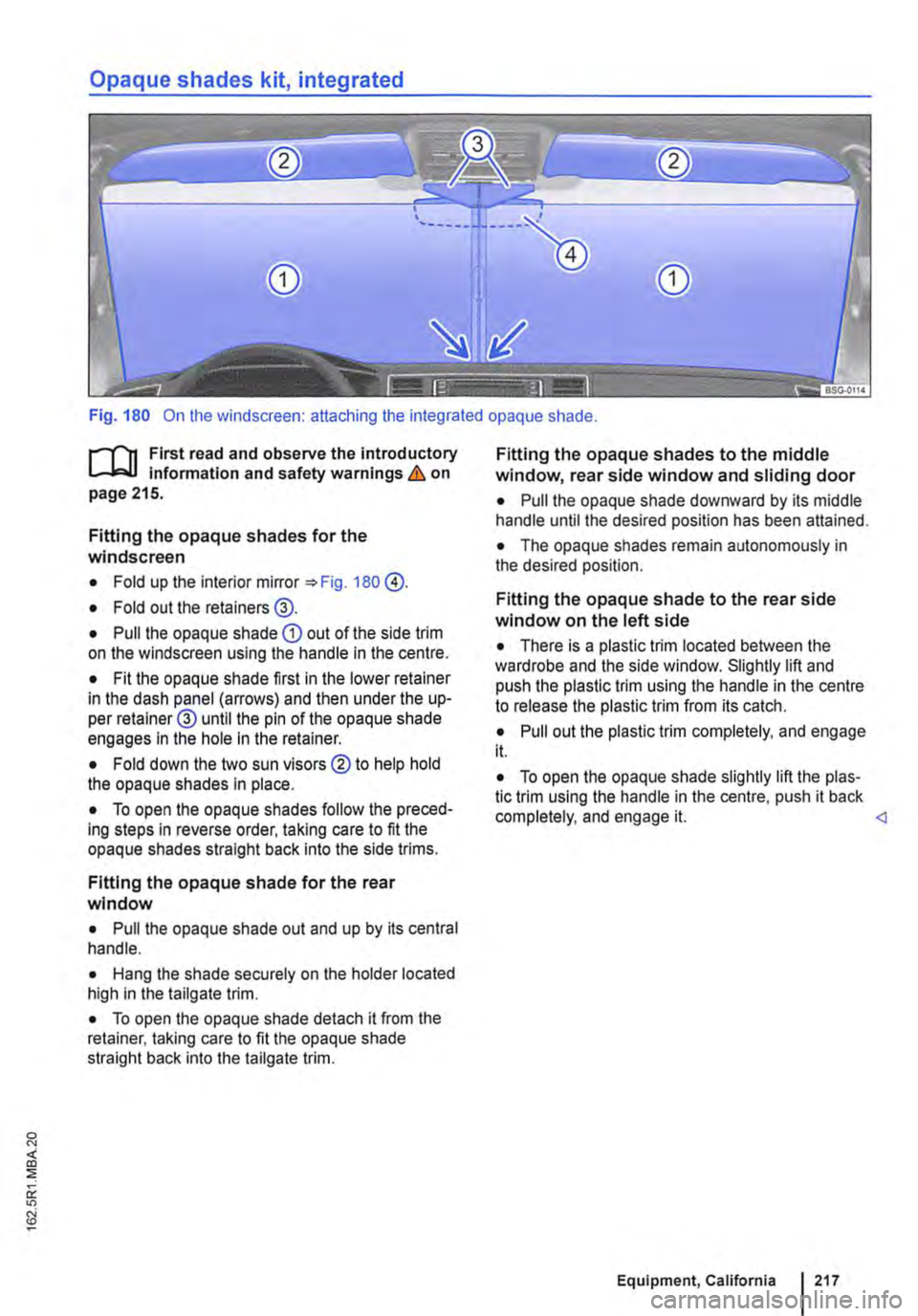
Fig. 180 On the windscreen: attaching the integrated opaque shade.
f""""'('n First read and observe the introductory L-W.I information and safety warnings & on page 215.
Fitting the opaque shades for the windscreen
• Fold up the interior mirror 180 @.
• Fold out the retainers@.
• Pull the opaque shade CD out of the side trim on the windscreen using the handle in the centre.
• Fit the opaque shade first in the lower retainer in the dash panel (arrows) and then under the up-per retainer@ until the pin of the opaque shade engages In the hole in the retainer.
• Fold down the two sun visors ®to help hold the opaque shades in place.
• To open the opaque shades follow the preced-ing steps in reverse order, taking care to fit the opaque shades straight back Into the side trims.
Fitting the opaque shade for the rear window
• Pull the opaque shade out and up by its central handle.
• Hang the shade securely on the holder located high in the tailgate trim.
• To open the opaque shade detach it from the retainer, taking care to fit the opaque shade straight back into the tailgate trim.
Fitting the opaque shades to the middle window, rear side window and sliding door
• Pull the opaque shade downward by its middle handle until the desired position has been attained.
• The opaque shades remain autonomously in the desired position.
Fitting the opaque shade to the rear side window on the left side
• There is a plastic trim located between the wardrobe and the side window. Slightly lift and push the plastic trim using the handle in the centre to release the plastic trim from its catch.
• Pull out the plastic trim completely, and engage it.
• To open the opaque shade slightly lift the plas-tic trim using the handle in the centre, push it back completely, and engage it.
Page 264 of 486

Dual clutch gearbox DSG®
r-('n First read and observe the Introductory L-.lo:on Information and safety warnings & on page 260.
Description
The DSG® dual clutch gearbox is a gearbox which uses dual-clutch technology to change gear automatically. it uses a dual clutch and two independent gearboxes to enable very fast gear changes with no loss of torque. The DSG® dual clutch gearbox thus combines the performance and economy of a manual gearbox with the com-fort and convenience of a conventional automatic transmission.
How the system works
Engine power is transferred to the drive shafts via the gearbox. In order to change gears, the power transmission between the engine and the gearbox has to be interrupted. This is what the clutch is for.
With the DSG® dual clutch system with its two complementary gearboxes, one gearbox is always connected under load to the engine. When one gear is engaged, another gear is always preselec-
led in the other gearbox. The clutch on the non-driven gear is closed and the other is opened at the same time. This is what makes very fast gear changes possible.
The DSG® dual clutch gearbox is designed to be more efficient than an automatic gearbox. In an au-tomatic gearbox, the torque converter is constantly in use, whereas in the DSG® dual clutch system the idle clutch can be opened, thus saving fuel. With its efficiency, low weight and intelligent control system, the DSG® dual clutch system usually ena-bles fuel consumption equal to or lower than a manual gearbox.
like the manual gearbox, the clutch in the DSG dual clutch system is subject to wear. Regular maintenance is necessary, varying accord-ing to what type of DSG® dual clutch system is in-stalled. For more information see the service schedule. In the DSG® dual clutch system, if one gearbox malfunctions it is deactivated and the oth-er gearbox functions alone *page 267. If this happens, have the system checked as soon as possible by a qualified workshop.
Fig. 221 Selector lever for automatic gearbox with lock button (arrow) in left-hand drive vehicles. The controls are mirrored for right-hand drive vehicles.
264 I While driving
r-('n First read and observe the Introductory L-.lo:on Information and safety warnings & on page 260.
The selector lever is equipped with a selector lever lock. When changing the selector lever position from P to a driving gear, depress the brake pedal and push the lock button in the selector lever in the direction of the arrow *Fig. 221. To move the se-lector lever out of position N to position D or R, first depress and hold the brake pedal.
The current selector lever position or the selected gear will be shown in the instrument duster display if the ignition is switched on. .,..
Page 266 of 486

A WARNING (Continued)
• Never leave the vehicle in driving mode N. The vehicle will roll downhill irrespective of whether or not the engine is running.
CD
If the handbrake is not applied when the vehi-cle Is stationary and the brake pedal is released when then selector lever Is In position P, the vehicle may move a few centimetres forwards or backwards.
Changing gear with Tiptronic
Fig. 222 Selector lever in Tiptronic position (left-hand drive). The controls are mirrored for right-hand drive vehicles.
r--T'n First read and observe the introductory L-lc:J.I Information and safety warnings & on page 260.
With a DSG® dual clutch gearbox, Tip-
Ironic allows the gears to be shifted up
and down manually.
m If the lever is moved accidentally to N when l!J driving, take your foot off the accelerator. Wait for the engine revs in the neutral position be-fore selecting a position again.
m If the selector lever is left in any position oth-L!J er than P for long periods when the engine is switched off, the vehicle battery discharges.
Operating Tiptronic with the selector lever
• Push the selector lever from position D to the right into the Tiptronic gate & in osG® dual clutch gearbox: selecting a gear on page 265.
• Gently push the selector lever forwards G or back 8 to shift gear up or down 222.
CD
• When accelerating, the gearbox automati-cally shifts up to the next gear shortly before the maximum permitted engine speed Is reached.
• When shifting down a gear manually, the gearbox will not change gear until the engine can no longer be overrevved.
r--T'n First read and observe the introductory L-lc:J.I information and safety warnings & on page 260.
The gearbox changes the forward gears up and down automatically.
2661 While driving
Driving down hills
The steeper the gradient, the lower the gear you will need. Lower gears increase the braking effect of the engine. Never allow the vehicle to roll down mountains or hills in the neutral position N. ,..
Page 312 of 486

System limits
r-('n First read and observe the Introductory L-J,:.U Information and safety warnings & on page 307.
The area monitoring system (Front Assist) has physical and system-related limits. The driver may therefore feel that, in certain circumstances, some Front Assist reactions occur unexpectedly or with a delay. You should therefore always be prepared to take full control of the vehicle if necessary.
The following conditions can prevent Front Assist from reacting, or cause a delay in its reaction:
• In tight bends.
• If the accelerator is fully depressed.
• If Front Assist is switched off or there is a fault.
• If TCS or ESC is switched off manually.
• If the ESC is taking corrective action.
• If there is a fault in several brake lights on the vehicle or on a trailer with an electrical connection to the vehicle.
• If the radar sensor is dirty or covered.
• If the vehicle is reversing.
• Under hard acceleration.
• In snow or heavy rain.
• In case of narrow vehicles, e.g. motorbikes.
• If vehicles are travelling slightly to the left or right of your vehicle.
• If vehicles are crossing in front of your vehicle.
• If there is oncoming traffic.
• In uncertain traffic situations.
• 1/Vhen loads or attachment parts on other vehi-cles protrude to the side, rear or above the normal dimensions of the vehicle.
COJ Introduction
This chapter contains information on the following subjects:
Indicator lamp ... .
Operation ....... .
Driving situations ..........•.............
313
314
315
The lane change assist system (Side As-
sist) provides assistance when checking
for traffic behind the vehicle.
The lane change assist system cannot be switched on if the factory-fitted towing bracket is electrically connected to the trailer. The lane change assist system must be switched off manually for non-fac-tory-fitted towing brackets.
The lane change assist system has been designed for use on surfaced roads only.
Additional information and warnings:
• Exterior views =<>page 5
• Volkswagen information system =<>page 24
• Accessories, modifications, repairs and renewal of parts =<>page 394.
3121 While drivmg
A WARNING
The Intelligent technology of the lane change assist system (Side Assist) cannot change the laws of physics or the system-related ve-hicle limitations. Always take care when us-Ing the lane change assist system as you could otherwise cause accidents or Injuries. The system Is not a substitute for the full concentration of the driver.
• Adapt your speed and distance from the vehicles ahead to suit visibility, weather, road and traffic conditions.
• Your hands should always be on the steer-Ing wheel so that you can steer at any time.
• Pay attention to the visual displays in the exterior mirror housing and in the Instrument cluster display, and respond to the com-mands.
• The lane change assist system may react to special roadside structures, e.g. high or offset crash barriers. This can lead to error warnings. ,..
Page 313 of 486

A WARNING (Continued)
• Never use the lane change assist system on unsurfaced roads. The lane change assist system has been designed exclusively for use on surfaced roads.
• Always pay close attention to what Is hap-pening around the vehicle.
• Never use the lane change assist system, If the radar sensors are dirty, covered or dam-aged. These circumstances can Impair the proper functioning of the system.
• lt may be hard to see the display In the ex-terior mirror In direct sunlight.
Indicator lamp
.---T'n First read and observe the introductory L-J,:..IJ Information and safety warnings & on page 312.
Lights up or Possible cause flashes
The lane change assist system is cur-rently not available.
Several warning and indicator lamps will light up briefly as a functional check when the ignition is switched on. They will go out after a few seconds.
m Only Volkswagen-approved vehicle paints L!..J may be used on the rear bumper. Other vehi-cle paints could limit or even distort the function of the lane change assist system.
m If the lane change assist system does not L!..J function as described in this chapter, or after a collision with another vehicle, do not use the sys-tem. Go to a qualified workshop.
m Go to a qualified workshop and have the sys-L!..J tern checked ifthere is a fault in the system or after an accident.
Failure to observe illuminated warning lamps and text messages can lead to your vehicle breaking down in traffic, and can cause acci-dent and serious Injury.
• Never ignore any illuminated warning lamps or text messages.
• Stop the vehicle as soon as possible and when safe to do so.
Page 314 of 486

Operation
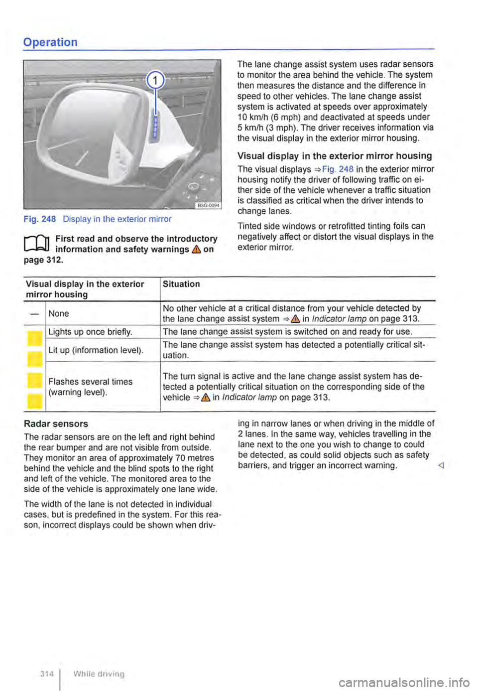
Fig. 248 Display in the exterior mirror
r-f"n First read and observe the introductory L-W! information and safety warnings & on page 312.
Visual display in the exterior Situation mirror housing
The lane change assist system uses radar sensors to monitor the area behind the vehicle. The system then measures the distance and the difference in speed to other vehicles. The lane change assist system is activated at speeds over approximately 10 km/h (6 m ph) and deactivated at speeds under 5 km/h (3 mph). The driver receives infonmation via the visual display in the exterior mirror housing.
Visual display in the exterior mirror housing
The visual displays 248 in the exterior mirror housing notify the driver of following traffic on ei-ther side of the vehicle whenever a traffic situation is classified as critical when the driver intends to change lanes.
Tinted side windows or retrofitted tinting foils can negatively affect or distort the visual displays in the exterior mirror.
None No other vehicle at a critical distance from your vehicle detected by -the lane change assist system & in Indicator lamp on page 313.
Lights up once briefly. The lane change assist system is switched on and ready for use.
Lit up (information level). The lane change assist system has detected a potentially critical sit-uation.
Flashes several times The turn signal is active and the lane change assist system has de-
(warning level). tected a potentially critical situation on the corresponding side of the in Indicator/amp on page 313.
Radar sensors
The radar sensors are on the left and right behind the rear bumper and are not visible from outside. They monitor an area of approximately 70 metres behind the vehicle and the blind spots to the right and left of the vehicle. The monitored area to the side of the vehicle is approximately one lane wide.
The width of the lane is not detected in individual cases. but is predefined in the system. For this rea-son. incorrect displays could be shown when driv-
314 I While driving
ing in narrow lanes or when driving in the middle of 2 lanes. In the same way, vehicles travelling in the lane next to the one you wish to change to could be detected, as could solid objects such as safety barriers. and trigger an incorrect warning.
Page 315 of 486
![VOLKSWAGEN TRANSPORTER 2011 Owners Manual Driving situations
A
(I
Fig. 249 [A] Driving situation when overtaking with traffic behind the vehicle [81 Visual display in the left-hand exterior mirror.
A
Fig. 250 situation when overtaking an VOLKSWAGEN TRANSPORTER 2011 Owners Manual Driving situations
A
(I
Fig. 249 [A] Driving situation when overtaking with traffic behind the vehicle [81 Visual display in the left-hand exterior mirror.
A
Fig. 250 situation when overtaking an](/manual-img/18/55786/w960_55786-314.png)
Driving situations
A
(I
Fig. 249 [A] Driving situation when overtaking with traffic behind the vehicle [81 Visual display in the left-hand exterior mirror.
A
Fig. 250 situation when overtaking and pulling in. [B' Visual display in the right-hand exterior mirror.
rll1 First read and observe the introductory L-W.I Information and safety warnings & on page 312.
The following driving situations trigger a light in the exterior mirror 249 [ID (arrow) or 250 [ID (arrow):
• When another vehicle is overtaking your vehi-cle 249
• When overtaking another vehicle 250 with a speed difference of up to approximately 15 km/h (9 m ph). No display will be shown if the take-over manoeuvre is much faster.
The display in the exterior mirror will be shown ear-lier the faster you are nearing another vehicle as the lane change assist system calculates the
speed difference to other vehicles. For this reason, the display could be activated at different times de-spite your vehicle being at the same distance from other vehicles.
Physical and system-specific limits
The lane change assist system might, for example, interpret the traffic situation incorrectly in certain driving situations. In the following situations, for ex-ample:
• In tight bends.
• When road lanes are of varying width.
• At the brow of a hill.
• In poor weather conditions.
• Where there are special roadside structures, e.g. high or offset crash barriers. <1
Driver Alert System (recommendation for rest breaks)
o::n Introduction
This chapter contains information on the following subjects:
Function and operation by the user.. . . . 316
The Driver Alert System informs the driv-
er if their driving shows signs of tired-
ness.
Driver assist systems 315
Page 380 of 486

Vehicle care and maintenance
Caring for and cleaning the vehicle exterior
o:n Introduction
This chapter contains information on the following subjects:
Washing the vehicle . . . . . . . . . . . . . . . 381
Washing the vehicle with a high-pressure cleaner . . . . . . . . . . . . . . . . . . . . . . . . . . . 382 Cleaning windows and exterior mirrors . . . . . . 382
Cleaning and changing wiper blades 383
Waxing and polishing the vehicle 384
Cleaning and caring for chrome and aluminium trim parts . . . . . . . . . . . . . . 385
Cleaning and caring for the decorative film . . 385
Cleaning wheels . . . . . . . . . . . . . . . . . . . . . 386
Care of rubber seals . . . . . . . . . . . . . . . . . . . . . 386
De-icing door lock cylinders . . . . . . • . . . . . . . . 387
Undersea! . . . . . . . . . . . . . . . . . . . . . . . . . . . . . . 387
Cleaning the engine compartment . 387
Regular and expert care helps to maintain the val-ue of the vehicle. Proper maintenance may also be one of the requirements for the approval of warran-ty claims in the event of corrosion or paint defects.
Suitable care products are available from Volkswa-gen Commercial Vehicles dealers.
Additional information and warnings:
• Preparation for working in the engine compart-ment ::-page 350
• Cleaning and caring for the interior ::-page 388
• Accessories, modifications, repairs and renewal of parts ::-page 394
A WARNING
Car care products can be toxic and hazard-ous. Unsuitable care products and Incorrect application of care products can cause acci-dents, serious Injuries, burns or poisoning.
• The care product must be kept In Its origi-nal sealed container.
380 Cleaning and maintenance
A WARNING (Continued)
• Read the manufacturer's Instructions .
• Never store car care products in empty food containers, bottles or any other non-original containers as people finding these containers may not know that they contain care products.
• Keep children away from care products .
• The products can give off harmful fumes during use. They should therefore only be used outside or In well-ventilated spaces.
• Never use fuel, turpentine, engine oil, nail varnish remover or other volatile fluids to wash, clean or care for your vehicle. These substances are toxic and highly Inflammable.
A WARNING
Incorrect care and cleaning of vehicle parts can Impair the safety features of the vehicle and thus cause serious Injury.
• Vehicle parts must be cleaned according to the manufacturer's Instructions.
• Only use approved or recommended cleaning products.
CD
Cleaning agents that contain solvents attack the material and can cause damage.
r:Q:... In the interests of environmental protection, "C!S the vehicle should only be washed in special-ly provided wash bays. This prevents waste water contaminated with oil, grease or fuel from entering the sewerage system. In some countries, washing vehicles anywhere else may be prohibited.
r:Q:... Environmentally-friendly care products "C!S should be used.
r:Q:... Leftover car care products should not be dis-"C!S posed of with ordinary household waste. Read the manufacturer's instructions.