2011 SUBARU TRIBECA warning light
[x] Cancel search: warning lightPage 154 of 422
amount of fuel remaining in the tank and
the average rate of fuel consumption.
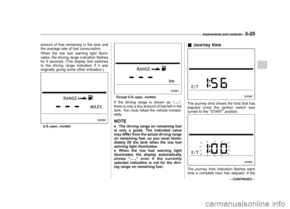
When the low fuel warning light illumi-
nates, the driving range indication flashes
for 5 seconds. (The display first switches
to the driving range indication if it was
originally giving some other indication.)
U.S.-spec. models
Except U.S.-spec. models
If the driving range is shown as “
”,
there is only a tiny amount of fuel left in the
tank. You must refuel the vehicle immedi-
ately. NOTE . The driving range on remaining fuel
is only a guide. The indicated value
may differ from the actual driving range
on remaining fuel, so you must imme-
diately fill the tank when the low fuel
warning light illuminates.. When the low fuel warning light
illuminates, the display automaticallyshows “
”even if the currently
selected indication is not for the driv-
ing range on remaining fuel. &
Journey time
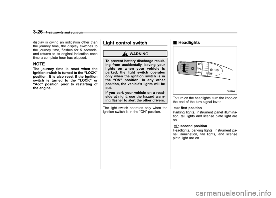
The journey time shows the time that has
elapsed since the ignition switch was
turned to the “START ”position.
The journey time indication flashes each
time a complete hour has elapsed. If the Instruments and controls
3-25
– CONTINUED –
Page 155 of 422
3-26Instruments and controls
display is giving an indication other than
the journey time, the display switches to
the journey time, flashes for 5 seconds,
and returns to its original indication each
time a complete hour has elapsed. NOTE
The journey time is reset when the
ignition switch is turned to the “LOCK ”
position. It is also reset if the ignition
switch is turned to the “LOCK ”or
“ Acc ”position prior to restarting of
the engine. Light control switch
WARNING
To prevent battery discharge result-
ing from accidentally leaving your
lights on when your vehicle is
parked, the light switch operates
only when the ignition switch is inthe “ON ”position. In any other
position, the vehicle ’s lights will be
out.
If you park your vehicle on a road-
side at night, use the hazard warn-
ing flasher to alert the other drivers.
The light switch operates only when the
ignition switch is in the “ON ”position. &
Headlights
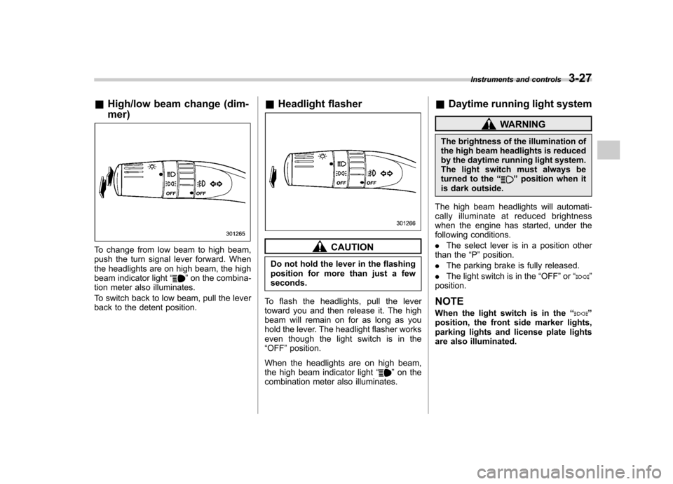
To turn on the headlights, turn the knob on
the end of the turn signal lever.
first position
Parking lights, instrument panel illumina-
tion, tail lights and license plate light areon.
second position
Headlights, parking lights, instrument pa-
nel illumination, tail lights, and license
plate light are on.
Page 156 of 422
&High/low beam change (dim- mer)
To change from low beam to high beam,
push the turn signal lever forward. When
the headlights are on high beam, the high
beam indicator light “
”on the combina-
tion meter also illuminates.
To switch back to low beam, pull the lever
back to the detent position. &
Headlight flasher
CAUTION
Do not hold the lever in the flashing
position for more than just a fewseconds.
To flash the headlights, pull the lever
toward you and then release it. The high
beam will remain on for as long as you
hold the lever. The headlight flasher works
even though the light switch is in the“ OFF ”position.
When the headlights are on high beam,
the high beam indicator light “
”on the
combination meter also illuminates. &
Daytime running light system
WARNING
The brightness of the illumination of
the high beam headlights is reduced
by the daytime running light system.
The light switch must always be
turned to the “
”position when it
is dark outside.
The high beam headlights will automati-
cally illuminate at reduced brightness
when the engine has started, under the
following conditions. . The select lever is in a position other
than the “P ”position.
. The parking brake is fully released.
. The light switch is in the “OFF ”or “
”
position.
NOTE
When the light switch is in the “
”
position, the front side marker lights,
parking lights and license plate lights
are also illuminated. Instruments and controls
3-27
Page 163 of 422
3-34Instruments and controls
When the wiper switch is in the “
”
position, turn the dial to adjust the operat-
ing interval of the wiper.
The operating interval can be adjusted in
nine steps.
The intermittent operation interval varies
depending on the vehicle speed in any of
the adjustment steps (longer when the
vehicle speed is low; shorter when the
vehicle speed is high). ! Washer
To wash the windshield, push the washer
button at the end of the wiper control lever.
The washer fluid sprays until you release
the washer button. The wipers operate
while you push the button. NOTE
The windshield washer fluid warning
light illuminates when the washer fluid
level in the tank has dropped to the
lower limit. If the warning light illumi-
nates, refill the tank with fluid. For the
tank refilling method, refer to
“Wind-
shield washer fluid ”F 11-29. &
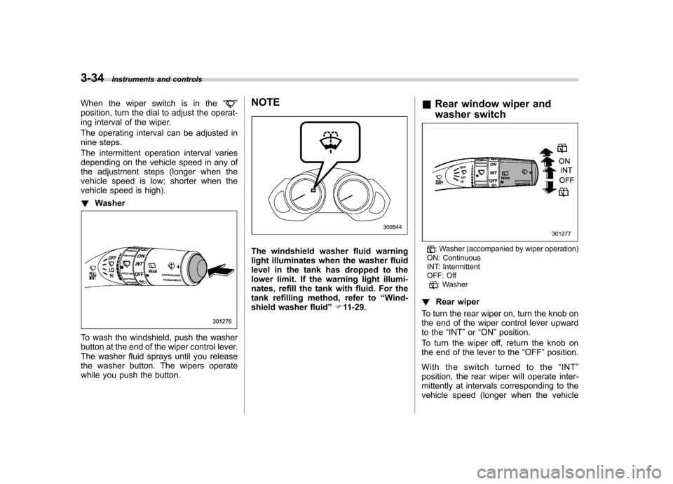
Rear window wiper and
washer switch: Washer (accompanied by wiper operation)
ON: Continuous
INT: Intermittent
OFF: Off
: Washer
! Rear wiper
To turn the rear wiper on, turn the knob on
the end of the wiper control lever upward
to the “INT ”or “ON ”position.
To turn the wiper off, return the knob on
the end of the lever to the “OFF ”position.
With the switch turned to the “INT ”
position, the rear wiper will operate inter-
mittently at intervals corresponding to the
vehicle speed (longer when the vehicle
Page 181 of 422
4-8Climate control
!Airflow mode selection button
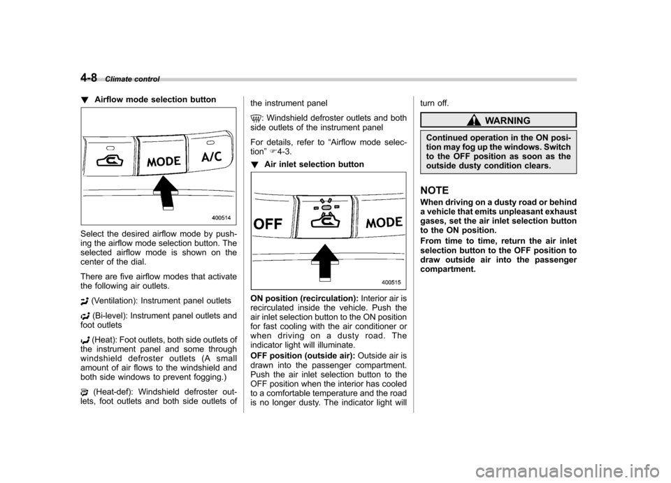
Select the desired airflow mode by push-
ing the airflow mode selection button. The
selected airflow mode is shown on the
center of the dial.
There are five airflow modes that activate
the following air outlets.
(Ventilation): Instrument panel outlets
(Bi-level): Instrument panel outlets and
foot outlets
(Heat): Foot outlets, both side outlets of
the instrument panel and some through
windshield defroster outlets (A small
amount of air flows to the windshield and
both side windows to prevent fogging.)
(Heat-def): Windshield defroster out-
lets, foot outlets and both side outlets of the instrument panel
: Windshield defroster outlets and both
side outlets of the instrument panel
For details, refer to “Airflow mode selec-
tion ”F 4-3.
! Air inlet selection button
ON position (recirculation): Interior air is
recirculated inside the vehicle. Push the
air inlet selection button to the ON position
for fast cooling with the air conditioner or
when driving on a dusty road. The
indicator light will illuminate.
OFF position (outside air): Outside air is
drawn into the passenger compartment.
Push the air inlet selection button to the
OFF position when the interior has cooled
to a comfortable temperature and the road
is no longer dusty. The indicator light will turn off.
WARNING
Continued operation in the ON posi-
tion may fog up the windows. Switch
to the OFF position as soon as the
outside dusty condition clears.
NOTE
When driving on a dusty road or behind
a vehicle that emits unpleasant exhaust
gases, set the air inlet selection button
to the ON position.
From time to time, return the air inlet
selection button to the OFF position to
draw outside air into the passengercompartment.
Page 231 of 422
6-14Interior equipment
Cargo area cover (if equipped)
The cargo area cover is provided for
covering the cargo area and to protect its
contents from direct sunlight. This cover is
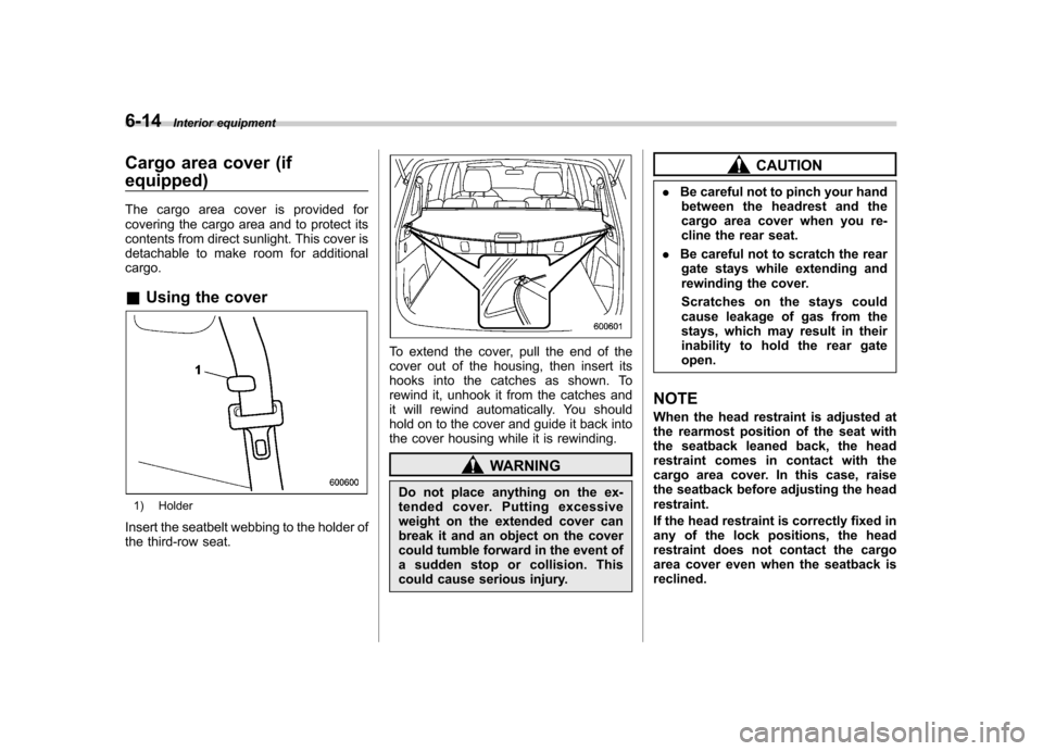
detachable to make room for additionalcargo. &Using the cover
1) Holder
Insert the seatbelt webbing to the holder of
the third-row seat.
To extend the cover, pull the end of the
cover out of the housing, then insert its
hooks into the catches as shown. To
rewind it, unhook it from the catches and
it will rewind automatically. You should
hold on to the cover and guide it back into
the cover housing while it is rewinding.
WARNING
Do not place anything on the ex-
tended cover. Putting excessive
weight on the extended cover can
break it and an object on the cover
could tumble forward in the event of
a sudden stop or collision. This
could cause serious injury.
CAUTION
. Be careful not to pinch your hand
between the headrest and the
cargo area cover when you re-
cline the rear seat.
. Be careful not to scratch the rear
gate stays while extending and
rewinding the cover.
Scratches on the stays could
cause leakage of gas from the
stays, which may result in their
inability to hold the rear gateopen.
NOTE
When the head restraint is adjusted at
the rearmost position of the seat with
the seatback leaned back, the head
restraint comes in contact with the
cargo area cover. In this case, raise
the seatback before adjusting the headrestraint.
If the head restraint is correctly fixed in
any of the lock positions, the head
restraint does not contact the cargo
area cover even when the seatback isreclined.
Page 234 of 422
HomeLink®Wireless Control
System (if equipped)
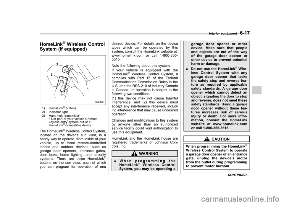
1) HomeLink®buttons
2) Indicator light
3) Hand-held transmitter* * Not part of your vehicle ’s remote
keyless entry system but of a HomeLink
®-compatible device.
The HomeLink
®Wireless Control System,
located on the driver ’s sun visor, is a
handy way to operate, from inside of your
vehicle, up to three remote-controlled
indoor and outdoor devices, such as
garage door openers, entrance gates,
door locks, home lighting, and security
systems. There are three HomeLink
®
buttons on the sun visor, each of which
you can program for operation of one desired device. For details on the device
types which can be operated by this
system, consult the HomeLink website at
www.homelink.com or call 1-800-355-3515.
Note the following about this system:
Ifyourvehicleisequippedwiththe HomeLink
®Wireless Control System, it
complies with Part 15 of the Federal
Communication Commission Rules in the
U.S. and the RSS-210 of Industry Canada
in Canada. Its operation is subject to the
following two conditions:
(1) this device may not cause harmful
interference, and (2) this device must
accept any interference received, includ-
ing interference that may cause undesiredoperation.
Changes and modifications to this system
by anyone other than an authorized
service facility could void authorization to
use this equipment.
HomeLink and the HomeLink house are
registered trademarks of Johnson Con-
trols, Inc.
WARNING
. When programming the
HomeLink
®Wireless Control
System, you may be operating a garage door opener or other
device. Make sure that people
and objects are out of the way
of the garage door opener or
other device to prevent potential
harm or damage.
. Do not use the HomeLink
®Wire-
less Control System with any
garage door opener that lacks
the safety stop and reverse fea-
ture as required by applicable
safety standards. A garage door
opener which cannot detect an
object, signaling the door to stop
and reverse, does not meet these
safety standards. Using a garage
door opener without these fea-
tures increases risk of serious
injury or death. For more infor-
mation, consult the HomeLink
website at www.homelink.com
or call 1-800-355-3515.
CAUTION
When programming the HomeLink
®
Wireless Control System to operate
a garage door opener or an entrance
gate, unplug the device ’s motor
from the outlet during programming
to prevent motor burnout. Interior equipment
6-17
– CONTINUED –
Page 238 of 422
3. Press and hold the hand-held trans-
mitter button. The HomeLink®indicator
light will flash, first slowly and then rapidly.
4. When the indicator light begins to flash
rapidly, release both buttons.
The programming for the previous device
is now erased and the new device can be
operated by pushing the HomeLink
®
button. & Erasing HomeLink
®button
memory
NOTE . Performing this procedure erases
the memory of all the preprogrammed
buttons simultaneously. The memory
of individual buttons cannot be erased.. It is recommended that upon the
sale of the vehicle, the memory of all
programmed HomeLink
®buttons be
erased for security purposes.
1. Press and hold the two outside buttons
until the indicator light begins to flash
(after 20 seconds).
2. Release both buttons. &
In case a problem occurs
If you cannot activate a device using the
corresponding HomeLink
®button after
programming, contact HomeLink at
www.homelink.com or call 1-800-355-
3515 for assistance. Rear view camera (if
equipped)
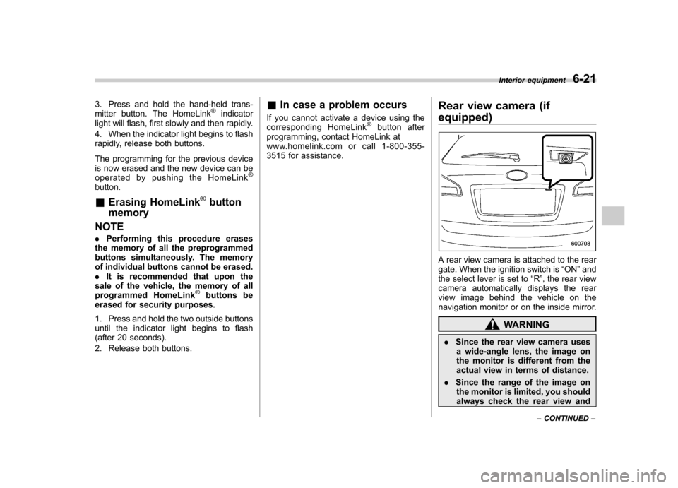
A rear view camera is attached to the rear
gate. When the ignition switch is
“ON ”and
the select lever is set to “R ”, the rear view
camera automatically displays the rear
view image behind the vehicle on the
navigation monitor or on the inside mirror.
WARNING
. Since the rear view camera uses
a wide-angle lens, the image on
the monitor is different from the
actual view in terms of distance.
. Since the range of the image on
the monitor is limited, you should
always check the rear view and Interior equipment
6-21
– CONTINUED –