2011 SUBARU TRIBECA tow
[x] Cancel search: towPage 168 of 422
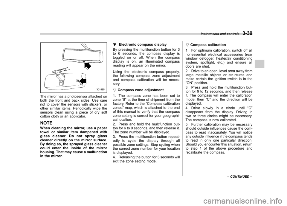
The mirror has a photosensor attached on
both the front and back sides. Use care
not to cover the sensors with stickers, or
other similar items. Periodically wipe the
sensors clean using a piece of dry soft
cotton cloth or an applicator. NOTE
When cleaning the mirror, use a paper
towel or similar item dampened with
glass cleaner. Do not spray glass
cleaner directly on the mirror surface.
By doing so, the sprayed glass cleaner
could enter the inside of the mirror
housing. That may cause a malfunction
in the mirror.!
Electronic compass display
By pressing the multifunction button for 3
to 6 seconds, the compass display is
toggled on or off. When the compass
display is on, an illuminated compass
reading will appear on the mirror.
Using the electronic compass properly,
the following compass zone adjustment
and compass calibration will be neces-
sary. ! Compass zone adjustment
1. The compass zone has been set to zone “8 ” at the time of shipment from the
factory. Refer to the “Compass calibration
zones ”map, which is attached to the end
of this manual to verify that the compass
zone setting is correct for your geographi-
cal location.
2. Press and hold the multifunction but-
ton for 6 to 9 seconds, and then release it.
The zone number will be displayed.
3. Press the multifunction button repeat-
edly to cycle the display through all
possible zone settings. Stop cycling when
the correct zone number for your location
is displayed.
4. Releasing the button for 3 seconds will
exit the zone setting mode. !
Compass calibration
1. For optimum calibration, switch off all
nonessential electrical accessories (rear
window defogger, heater/air conditioning
system, spotlight, etc.) and ensure all
doors are shut.
2. Drive to an open, level area away from
large metallic objects or structures and
make certain the ignition switch is in the“ ON ”position.
3. Press and hold the multifunction but-
ton for 9 to 12 seconds, and then release
it. The compass will enter the calibration
mode, then “C ” and the direction will be
displayed.
4. Drive slowly in a circle until “C ”
disappears from the display. Driving in
two or three circles might be necessary.
The compass is now calibrated.
5. Further calibration may be necessary
should outside influences cause the com-
pass to read inaccurately. You will notice
any outside influence if the compass tends
to read in only one particular direction.
Should you encounter this situation, return
to step 1 of the above procedure and
recalibrate the compass. Instruments and controls
3-39
– CONTINUED –
Page 180 of 422
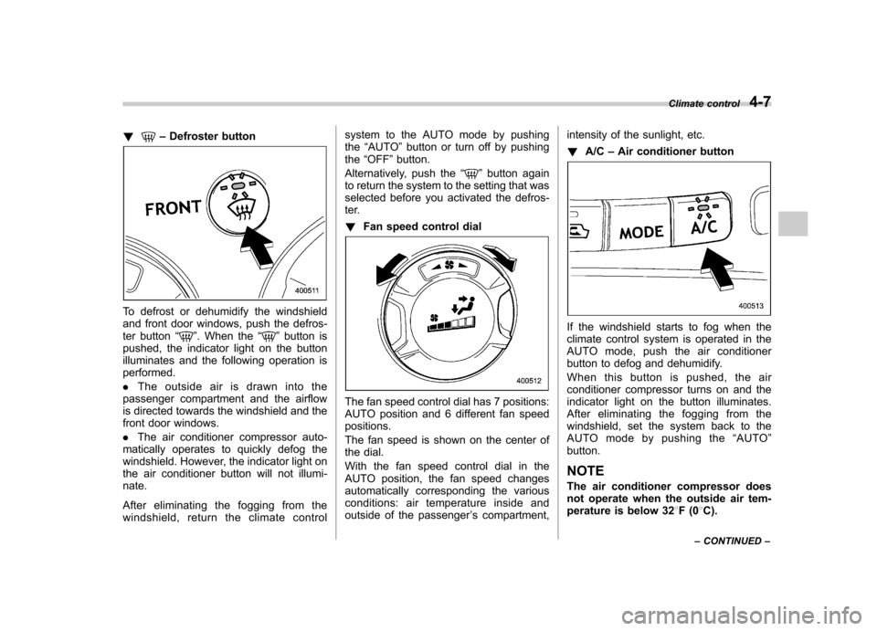
!–Defroster button
To defrost or dehumidify the windshield
and front door windows, push the defros-
ter button “
”. When the “”button is
pushed, the indicator light on the button
illuminates and the following operation isperformed. . The outside air is drawn into the
passenger compartment and the airflow
is directed towards the windshield and the
front door windows. . The air conditioner compressor auto-
matically operates to quickly defog the
windshield. However, the indicator light on
the air conditioner button will not illumi-nate.
After eliminating the fogging from the
windshield, return the climate control system to the AUTO mode by pushingthe
“AUTO ”button or turn off by pushing
the “OFF ”button.
Alternatively, push the “
”button again
to return the system to the setting that was
selected before you activated the defros-
ter. ! Fan speed control dial
The fan speed control dial has 7 positions:
AUTO position and 6 different fan speedpositions.
The fan speed is shown on the center of
the dial.
With the fan speed control dial in the
AUTO position, the fan speed changes
automatically corresponding the various
conditions: air temperature inside and
outside of the passenger ’s compartment, intensity of the sunlight, etc. !
A/C –Air conditioner button
If the windshield starts to fog when the
climate control system is operated in the
AUTO mode, push the air conditioner
button to defog and dehumidify.
When this button is pushed, the air
conditioner compressor turns on and the
indicator light on the button illuminates.
After eliminating the fogging from the
windshield, set the system back to the
AUTO mode by pushing the “AUTO ”
button.
NOTE
The air conditioner compressor does
not operate when the outside air tem-
perature is below 32 8F(0 8C).
Climate control
4-7
– CONTINUED –
Page 222 of 422
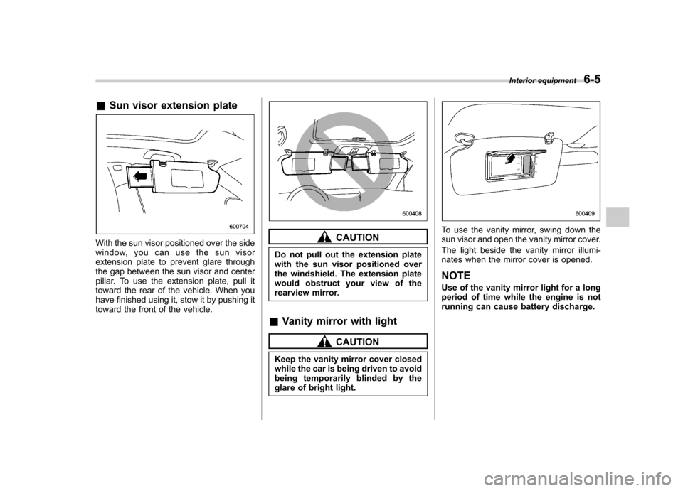
&Sun visor extension plate
With the sun visor positioned over the side
window, you can use the sun visor
extension plate to prevent glare through
the gap between the sun visor and center
pillar. To use the extension plate, pull it
toward the rear of the vehicle. When you
have finished using it, stow it by pushing it
toward the front of the vehicle.CAUTION
Do not pull out the extension plate
with the sun visor positioned over
the windshield. The extension plate
would obstruct your view of the
rearview mirror.
& Vanity mirror with light
CAUTION
Keep the vanity mirror cover closed
while the car is being driven to avoid
being temporarily blinded by the
glare of bright light.
To use the vanity mirror, swing down the
sun visor and open the vanity mirror cover.
The light beside the vanity mirror illumi-
nates when the mirror cover is opened. NOTE
Use of the vanity mirror light for a long
period of time while the engine is not
running can cause battery discharge. Interior equipment
6-5
Page 257 of 422
7-14Starting and operating
is started.
If the select lever does not move from the “P ” position with the brake pedal de-
pressed, the select lever button pushed
in, and the ignition switch in the ON
position, refer to “Shift lock function ”F 7-
14. ! R (Reverse)
This position is for backing the vehicle.
To shift from the “N ” to “R ”position, stop
the vehicle completely then move the
lever to the “R ” position while pushing
the select lever button. ! N (Neutral)
This position is for restarting a stalled engine.
In this position the wheels and transmis-
sion are not locked. In this position, the
transmission is neutral; the vehicle will roll
freely, even on the slightest incline unless
the parking brake or foot brake is applied.
Avoid coasting with the transmission neutral.
During coasting, there is no engine brak-
ing effect.
NOTE
When the ignition switch has been
turned to the “LOCK ”position, move-
ment of the select lever from the “N ” position to the
“R ” position is possible
for a limited time period by depressing
the brake pedal and then becomes
impossible. If the select lever becomes
impossible to be moved after a limited
time period, turn the ignition switch tothe “ON ”position. You will then be able
to move the select lever to the “P ”
position.
WARNING
Do not drive the vehicle with the
select lever in the “N ” (Neutral)
position. Engine braking has no
effect in this condition and the risk
of an accident is consequently in-creased.
! D (Drive)
This position is for normal driving.
The transmission automatically shifts into
a suitable gear from 1st to 5th according to
the vehicle speed and the acceleration
you require.
When more acceleration is required in this
position, depress the accelerator pedal
fully to the floor and hold that position. The
transmission will automatically downshift
to 4th, 3rd, 2nd or 1st gear. When you
release the pedal, the transmission will return to the original gear position.
To use the SPORT mode, move the lever
from this position into the manual gate.
To use the manual mode, move the lever
from this position into the manual gate
then move it toward the
“+ ” and “� ” ends.
! While climbing a grade
When driving up a hill, undesired upshift to
4th or 5th gear is prevented from taking
place when the accelerator is released.
This minimizes the chance of subsequent
downshifting to a lower gear when accel-
erating again. This prevents repeated
upshifting and downshifting resulting in a
smoother operation of the vehicle.
NOTE
The transmission may downshift to 2nd
or 1st gear, depending on the way the
accelerator pedal is depressed to ac-
celerate the vehicle again. & Shift lock function
The shift lock function helps prevent the
improper operation of the select lever. . The select lever cannot be operated
unless the ignition switch is turned to the “ ON ”position and the brake pedal is
depressed. . The select lever cannot be moved from
Page 260 of 422

Gearshifts can be performed using the
select lever.
Shift to the next-higher gear by briefly
pushing the select lever toward the“+ ”
end of the manual gate.
Shift to the next-lower gear by briefly
pulling the select lever toward the “� ”
end of the manual gate. NOTE
Please read the following points care-
fully and bear them in mind when using
the manual mode. . When the temperature of the engine
oil is higher than normal, warning
beeps are emitted and the shift position
indicator shows “� ”. If these warnings
are issued, deselect the manual mode
to protect the engine from damage. .
The transmission does not automa-
tically shift up in the manual mode.
Perform gearshifts in accordance with
road conditions so that the tachometer
needle does not enter the red zone. If
the engine speed reaches a predeter-
mined level, a fuel-cut function will
operate. Shift up if this happens. Also,
the transmission may automatically
shift up to protect the engine.. If you attempt to shift down when
the engine speed is too high, i.e., when
a downshift would push the tachometer
needle beyond the red zone, beeps will
be emitted to warn you that the down-
shift is not possible. . If you attempt to shift up when the
vehicle speed is too low, the transmis-
sion will not respond.. You can perform a skip-shift (for
example, from 4th to 2nd) by operating
the select lever twice in rapid succes-sion.. The transmission automatically se-
lects 1st gear when the vehicle stopsmoving.. If the temperature of the automatic
transmission fluid becomes too high,the “AT OIL TEMP ”warning light will
illuminate and upshifts to 5th gear will
not be possible. Immediately stop the
vehicle in a safe place and let the
engine idle until the warning light turns off.
& Driving tips
. On a road surface where there is a risk
of wheelspin (for example, a snow- or
gravel-covered road), you can pull away
from a standstill safely and easily by first
selecting the 2nd gear of the manualmode. . Always apply the foot or parking brake
when the vehicle is stopped in the “D ”or
“ R ”position.
. Always set the parking brake when
parking your vehicle. Do not hold the
vehicle with only the transmission. . Do not keep the vehicle in a stationary
position on an uphill grade by using the “ D ”position. Use the brake instead.
. The engine may, on rare occasions,
knock when the vehicle rapidly acceler-
ates or rapidly pulls away from a standstill.
This phenomenon does not indicate aproblem. . A slight reduction in output torque may
occur before the engine warms up. Starting and operating
7-17
– CONTINUED –
Page 266 of 422
warning light illuminate simultaneously,
take the following steps.
1. Stop the vehicle in the nearest safe,
flat location.
2. Shut down the engine, apply the
parking brake, and then restart it.
3. Release the parking brake. If both
warning lights turn off, the EBD system
may be malfunctioning.
Drive carefully to the nearest SUBARU
dealer and have the system inspected.
4. If both warning lights illuminate again
and remain illuminated after the engine
has been restarted, shut down the engine
again, apply the parking brake, and check
the brake fluid level. Refer to“Brake fluid ”
F 11-18.
5. If the brake fluid level is not below the“ MIN ”mark, the EBD system may be
malfunctioning. Drive carefully to the
nearest SUBARU dealer and have the
system inspected.
6. If the brake fluid level is below the “ MIN ”mark, DO NOT drive the vehicle.
Instead, have the vehicle towed to the
nearest SUBARU dealer for repair.
WARNING
. Driving with the brake system
warning light illuminated is dan- gerous. This indicates your brake
system may not be working
properly. If the light remains
illuminated, have the brakes in-
spected by a SUBARU dealer
immediately.
. If at all in doubt about whether
the brakes are operating prop-
erly, do not drive the vehicle.
Have your vehicle towed to the
nearest SUBARU dealer for re-
pair. Vehicle Dynamics Control system
WARNING
Always use the utmost care in driving –overconfidence because
you are driving with a Vehicle Dy-
namics Control system equipped
vehicle could easily lead to a ser-
ious accident.
CAUTION
. Even if your vehicle is equipped
with Vehicle Dynamics Control
system, winter tires should be
used when driving on snow-cov-
ered or icy roads; in addition,
vehicle speed should be reduced
considerably. Simply having a
Vehicle Dynamics Control sys-
tem does not guarantee that the
vehicle will be able to avoid
accidents in any situation.
. Activation of the Vehicle Dy-
namics Control system is an
indication that the road being
travelled on has a slippery sur-
face; since having Vehicle Dy-
namics Control is no guarantee Starting and operating
7-23
– CONTINUED –
Page 267 of 422

7-24Starting and operating
that full vehicle control will be
maintained at all times and under
all conditions, its activation
should be seen as a sign that
the speed of the vehicle should
be reduced considerably.
. Whenever suspension compo-
nents, steering components, or
an axle are removed from a
vehicle equipped with Vehicle
Dynamics Control system, have
an inspection of that system
performedbyanauthorized
SUBARU dealer.
. The following precautions should
be observed in order to ensure
that the Vehicle Dynamics Con-
trol system is operating properly. – All four wheels should be
fitted with tires of the same
size, type, and brand. Further-
more, the amount of wear
should be the same for all
four tires.
– Keep the tire pressure at the
proper level as shown on the
vehicle placard attached to
the driver ’s side door pillar.
In the event of wheelspin and/or skidding
on a slippery road surface and/or during cornering and/or an evasive maneuver,
the Vehicle Dynamics Control system
adjusts the engine
’s output and the
wheels ’respective braking forces to help
maintain traction and directional control. . Traction Control Function
The traction control function is designed to
prevent spinning of the driving wheels on
slippery road surfaces, thereby helping to
maintain traction and directional control.
Activation of this function is shown by
steady illumination of the Vehicle Dy-
namics Control operation indicator light. . Skid Suppression Function
The skid suppression function is designed
to help maintain directional stability by
suppressing the wheels ’tendency to slide
sideways during steering operations. Acti-
vation of this function is shown by flashing
of the Vehicle Dynamics Control operation
indicator light.
NOTE . Slight twitching of the brake pedal
may be felt when the Vehicle Dynamics
Control system operates; a small de-
gree of vehicle or steering wheel shak-
ing may also be noticed in this situa-
tion. These are normal characteristics
of Vehicle Dynamics Control operation
and are no cause for alarm.. When driving off immediately after starting the engine, a short operation
noise may be noticed coming from the
engine compartment. This noise is
generated as a result of a check being
performed on the Vehicle Dynamics
Control system and is normal..
Depending on the timing of activa-
tion of the brakes, the brake pedal may
seem to jolt when you drive off after
starting the engine. This is a conse-
quence of the Vehicle Dynamics Con-
trol operational check and is normal.. In the circumstances shown in the
following list, the vehicle may be more
unstable than it feels to the driver. The
Vehicle Dynamics Control System may
therefore operate. Such operation does
not indicate a system malfunction.
–on gravel-covered or rutted
roads – on unfinished roads
– when the vehicle is towing a
trailer– when the vehicle is fitted with
snow tires or winter tires
. Activation of the Vehicle Dynamics
Control system will cause operation of
the steering wheel to feel slightly
different compared to that for normalconditions. . Even if the vehicle is equipped with
a Vehicle Dynamics Control system, it
Page 274 of 422
.towing a trailer
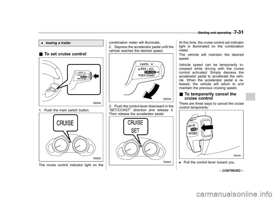
& To set cruise control
1. Push the main switch button.
The cruise control indicator light on the combination meter will illuminate.
2. Depress the accelerator pedal until the
vehicle reaches the desired speed.
3. Push the control lever downward in the “
SET/COAST ”direction and release it.
Then release the accelerator pedal.
At this time, the cruise control set indicator
light is illuminated on the combination
meter.
The vehicle will maintain the desired speed.
Vehicle speed can be temporarily in-
creased while driving with the cruise
control activated. Simply depress the
accelerator pedal to accelerate the vehi-
cle. When the accelerator pedal is re-
leased, the vehicle will return to and
maintain the previous cruising speed. & To temporarily cancel the
cruise control
There are three ways to cancel the cruise
control temporarily:
. Pull the control lever toward you. Starting and operating
7-31
– CONTINUED –