2011 SUBARU IMPREZA WRX change time
[x] Cancel search: change timePage 108 of 458

&Disarming the system
Briefly press the “
”button (for less than
2 seconds) on the remote transmitter. The
driver ’s door will unlock, an electronic
chirp will sound twice, the turn signal
lights will flash twice. The flashing of the
security indicator light will then change
slowly (once approximately every 3 sec-
onds from twice approximately every 2
seconds), indicating that the alarm system
has been disarmed. NOTE
After disarming the alarm system,
briefly press the “
”button a second
time within 5 seconds to unlock all
other doors and the rear gate (5-door). ! Emergency disarming
If you cannot disarm the system using the
transmitter (i.e. the transmitter is lost,
broken or the transmitter battery is too
weak), you can disarm the system without
using the transmitter as follows. . Turn the ignition switch from the
“ LOCK ”to the “ON ”position with a
registered key. & Valet mode
When you choose the valet mode, the
alarm system does not operate. In valet
mode, the remote transmitter is used only for locking and unlocking the doors and
rear gate (5-door) and panic activation.
To enter the valet mode, change the
setting of your vehicle
’s alarm system for
deactivation mode. Refer to “Activating
and deactivating the alarm system ”F 2-
16. The security indicator light will con-
tinue to flash once every 3 seconds
indicating that the system is in the valetmode.
To exit valet mode, change the setting of
your vehicle ’s alarm system for activation
mode. Refer to “Activating and deactivat-
ing the alarm system ”F 2-16.
& Passive arming
When passive arming mode has been
programmed by the dealer, arming of the
system is automatically accomplished
without using the remote transmitter. Note
that in this mode, DOORS MUST BE
MANUALLY LOCKED. ! To enter the passive mode
If you wish to program the passive arming
mode, have it done by your SUBARU
dealer. !
Arming the system
CAUTION
In passive mode, the system will
automatically activate the alarm but
WILL NOT automatically lock the
doors. In order to lock the doors
you must either lock them as in-
dicated in step 4 below or with the
key once they have been closed.
Failure to lock the doors manually
will result in a higher security risk.
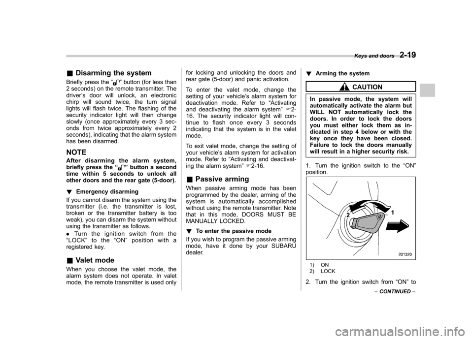
1. Turn the ignition switch to the “ON ”
position.
1) ON
2) LOCK
2. Turn the ignition switch from “ON ”to
Keys and doors
2-19
– CONTINUED –
Page 121 of 458

Instruments and controlsCruise control set indicator light ......................... 3-27
Front fog light indicator light (if equipped) .......... 3-27
Headlight indicator light (if equipped) ................. 3-27
Driver ’s control center differential auto indicator
light (STI) ......................................................... 3-27
Driver ’s control center differential indicator and
warning lights (STI) .......................................... 3-27
REV indicator light (STI) ..................................... 3-28
Clock ................................................................... 3-28
Information display ............................................ 3-29
Outside temperature indicator ............................ 3-29
Current fuel consumption (if equipped) ............... 3-30
Average fuel consumption .................................. 3-30
Turn off display of fuel consumption indicator .......................................................... 3-31
Light control switch ........................................... 3-31
Headlights. ......................................................... 3-32
High/low beam change (dimmer) ......................... 3-32
Headlight flasher ................................................ 3-32 Daytime running light system
............................. 3-33
Turn signal lever ................................................ 3-33
Illumination brightness control ......................... 3-33
Headlight beam leveler (if equipped) ............... 3-34
Front fog light switch (if equipped) .................. 3-36
Wiper and washer .............................................. 3-36
Windshield wiper and washer switches .............. 3-38
Rear window wiper and washer switch –
5-door ............................................................. 3-39
Mirrors ................................................................ 3-40
Inside mirror ...................................................... 3-40
Auto-dimming mirror/compass (if equipped) ....... 3-40
Auto-dimming mirror/compass with HomeLink
®(if equipped) .................................................... 3-41
Outside mirrors ................................................. 3-47
Defogger and deicer .......................................... 3-48
Tilt/telescopic steering wheel ........................... 3-50
Horn .................................................................... 3-51
Page 126 of 458

: Deactivated
NOTE . Your vehicle ’s initial movement
setting of the meter/gauge needles
has been set for activation “
”at the
time of shipment from the factory. . It is not possible to cancel the initial
movement setting of the meter/gauge
needles when the ignition switch is inthe “ON ”position. Cancel the setting
whentheignitionswitchisinthe“ LOCK ”or “Acc ”position.
& Meter/Gauge needle illumi-
nation setting (turbo models
except STI)
When the setting is activated or deacti-
vated, the meter needles and gauge
needles illuminate and turn off as follows. Activated:
When the driver ’s door is opened while
theignitionswitchisinthe “LOCK ”
position, the needles illuminate and turn
off after approximately 20 seconds. The
illumination of the needles gradually turns
off after the ignition switch is turned fromthe “ON ”position to the “LOCK ”position.
Deactivated:
The needles do not illuminate when thedriver ’s door is opened while the ignition switch is in the
“LOCK ”position. The
illumination of the needles turns off im-
mediately after the ignition switch is turned
from the “ON ”position to the “LOCK ”
position.
NOTE . Even during the illumination after
the driver ’s door is opened, if the
ignition switch is turned to the “ON ”
position, the combination meter will
illuminate as usual.. If the doors are locked by the remote
keyless entry system during the illumi-
nation after the driver ’s door is opened,
the illumination will be turned off.. Even while the illumination gradu-
ally turns off after the ignition switch is
turned to the “LOCK ”position, if the
ignition switch is turned to the “ON ”
position, the combination meter illumi-
nate as usual.
To change the setting:
1. Turn the ignition switch to the “LOCK ”
or “Acc ”position.
2. Press the trip knob to show “”or
“” on the odometer and trip meter
display. The display can be switched as
shown in the following illustration by
pressing the trip knob.
*: “”or “”, and “”or “”cannot
Instruments and controls
3-7
– CONTINUED –
Page 127 of 458

3-8Instruments and controls
be displayed when the ignition switch is
in the “ON ”position.
3. To change the current setting, press
the trip knob for at least 2 seconds.
: Activated
: Deactivated
NOTE
The initial illumination setting of the
meter/gauge needles of your vehicle
has been set for activation “
”at the
time of shipment from the factory.
& Speedometer
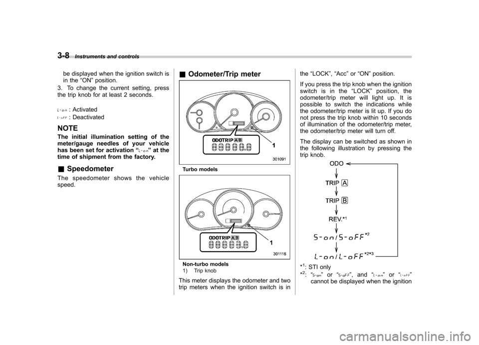
The speedometer shows the vehicle speed. &
Odometer/Trip meter
Turbo models
Non-turbo models
1) Trip knob
This meter displays the odometer and two
trip meters when the ignition switch is in the
“LOCK ”, “Acc ”or “ON ”position.
If you press the trip knob when the ignition
switch is in the “LOCK ”position, the
odometer/trip meter will light up. It is
possible to switch the indications while
the odometer/trip meter is lit up. If you do
not press the trip knob within 10 seconds
of illumination of the odometer/trip meter,
the odometer/trip meter will turn off.
The display can be switched as shown in
the following illustration by pressing the
trip knob.*1: STI only
*2: “” or “”,and “”or “”
cannot be displayed when the ignition
Page 131 of 458

3-12Instruments and controls
NOTE
Even if the REV alarm system is not set,
the REV indicator light will illuminate
whenever the engine speed enters thetachometer ’s red zone.
& Setting the alarm-level en-
gine speed
1. Push the trip knob to select “REV ”on
the combination meter.
2. When the trip knob is pushed for more
than 2 seconds, the thousands placeflashes.
3. Release your finger from the trip knob
once, then push and hold the trip knob
again. The number will change sequen-
tially from 2 to 7. Release your finger at
the desired alarm-level engine speed.
4. When the trip knob is pushed, the
hundreds place flashes.
5. Release your finger from trip knob
once, then push and hold the trip knob
again. The number will change sequen-
tially from 0 to 9. Release your finger at
the desired alarm-level engine speed.
6. When the trip knob is pushed, the
buzzer sounds and the REV alarm system
will automatically enter its new setting
mode (step 7 below), in which you can
activate or deactivate the buzzer.
The alarm-level engine speed can be set
(in 100 rpm steps) within the range from
2,000 rpm to 7,000 rpm.7. Every time that the trip knob is pushed
and held, the buzzer changes to activate
or deactivate.b –on: Activated
b –off: Deactivated
When the mode is changed to “activate ”,
the buzzer sounds.
8. Push the trip knob to complete the
setting procedure.
NOTE . The REV alarm system does not
operate while settings are being en- tered.. The speed-setting mode terminates
if “--00 ”rpm is selected.
. The speed-setting mode is canceled
if the ignition switch is turned from ON
Page 137 of 458

3-18Instruments and controls
approximately 2 seconds when the igni-
tion switch is turned to the “ON ”position.
After that, this indicator light/warning light
changes to BLUEand maintains illumina-
tion in BLUE. This BLUE illuminated light
turns off when the engine is warmed up
sufficiently.
If the engine coolant temperature in-
creases over the specified range, the
indicator light/warning light blinks inRED . At this time, the engine is close to
overheating.
If the engine coolant temperature in-
creases further, the indicator light/warning
light illuminates in REDcontinuously. At
this time, the engine may be overheating.
When the indicator light/warning light
blinks in REDor illuminates in RED, safely
stop the vehicle as soon as possible, and
refer to the emergency steps to take in the
case of engine overheating. Refer to“ Engine overheating ”F 9-13. After that,
have the system checked by your nearest
SUBARU dealer.
Also, if the indicator light/warning light
often blinks in RED, the electrical system
may be malfunctioning. Contact your
SUBARU dealer for an inspection. NOTE
If the engine is restarted after a certain
driving condition, this indicator light/
warning light may illuminate in RED.
However, this is not a malfunction if the
indicator light/warning light turns off
after a short time. &
Charge warning light
If this light illuminates when the engine is
running, it may indicate that the charging
system is not working properly.
If the light illuminates while driving or does
not turn off after the engine starts, stop the
engine at the first safe opportunity and
check the alternator belt. If the belt is
loose, broken or if the belt is in good
condition but the light remains illuminated,
contact your nearest SUBARU dealer
immediately. &Oil pressure warning light
If this light illuminates when the engine is
running, it may indicate that the engine oil
pressure is low and the lubricating system
is not working properly.
If the light illuminates while driving or does
not turn off after the engine starts, stop the
engine at the first safe opportunity and check the engine oil level. If the oil level is
low, add oil immediately. If the engine oil is
at the proper level but the light remains
illuminated, contact your nearest
SUBARU dealer immediately.
For details about checking the engine oil
level or adding the engine oil, refer to“
Engine oil ”F 11-10.
CAUTION
Do not operate the engine with the
oil pressure warning light illumi-
nated. This may cause serious en-
gine damage.
& AT OIL TEMP warning
light (AT models)
If this light illuminates when the engine is
running, it may indicate that the automatic
transmission fluid temperature is too hot.
If the light illuminates while driving, im-
mediately stop the vehicle in a safe place
and let the engine idle until the warning
light turns off. !Automatic transmission control
system warning
If the “AT OIL TEMP ”warning light flashes
after the engine starts, it may indicate that
the automatic transmission control system
Page 147 of 458

3-28Instruments and controls
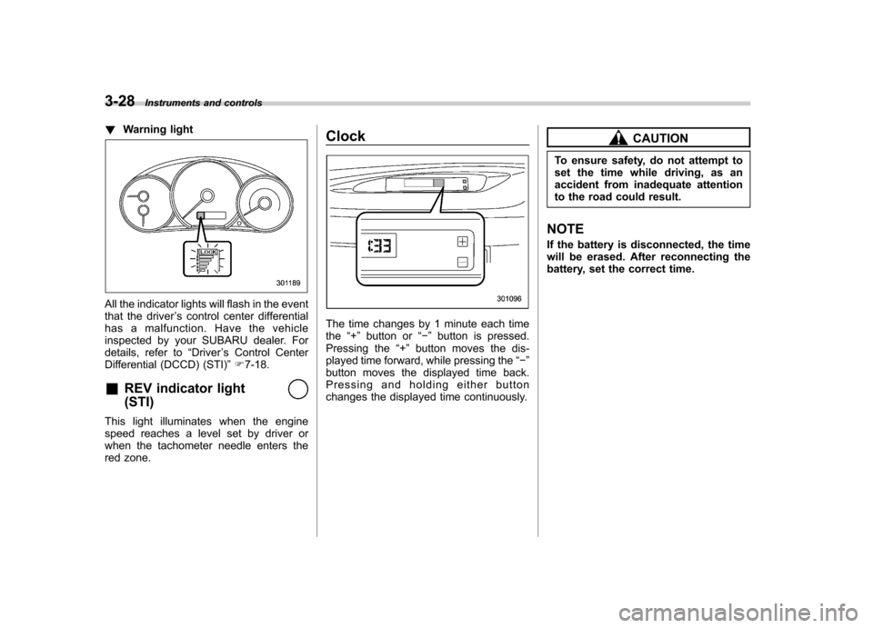
!Warning light
All the indicator lights will flash in the event
that the driver ’s control center differential
has a malfunction. Have the vehicle
inspected by your SUBARU dealer. For
details, refer to “Driver ’s Control Center
Differential (DCCD) (STI) ”F 7-18.
& REV indicator light (STI)
This light illuminates when the engine
speed reaches a level set by driver or
when the tachometer needle enters the
red zone. Clock
The time changes by 1 minute each time the
“+ ” button or “� ” button is pressed.
Pressing the “+ ” button moves the dis-
played time forward, while pressing the “� ”
button moves the displayed time back.
Pressing and holding either button
changes the displayed time continuously.
CAUTION
To ensure safety, do not attempt to
set the time while driving, as an
accident from inadequate attention
to the road could result.
NOTE
If the battery is disconnected, the time
will be erased. After reconnecting the
battery, set the correct time.
Page 152 of 458

&Daytime running light system
WARNING
The brightness of the illumination of
the high beam headlights is reduced
by the daytime running light system.
The light switch must always be
turned to the “
”position when it
is dark outside.
The high beam headlights will automati-
cally illuminate at reduced brightness
when the engine has started, under the
following conditions: . The select lever is in a position other
than the “P ”position (AT models).
. The parking brake is fully released.
. The light switch is in the “OFF ”or “
”
position.
NOTE
When the light switch is in the “
”
position, the front side marker lights,
tail lights and license plate lights areilluminated. Turn signal lever
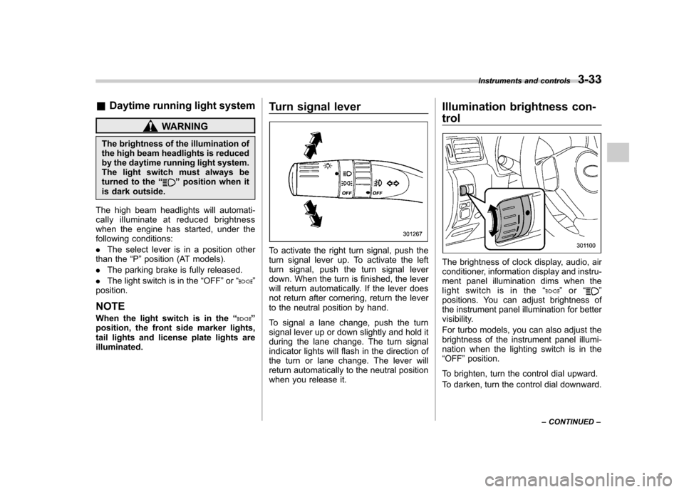
To activate the right turn signal, push the
turn signal lever up. To activate the left
turn signal, push the turn signal lever
down. When the turn is finished, the lever
will return automatically. If the lever does
not return after cornering, return the lever
to the neutral position by hand.
To signal a lane change, push the turn
signal lever up or down slightly and hold it
during the lane change. The turn signal
indicator lights will flash in the direction of
the turn or lane change. The lever will
return automatically to the neutral position
when you release it.Illumination brightness con- trol
The brightness of clock display, audio, air
conditioner, information display and instru-
ment panel illumination dims when the
light switch is in the
“
”or “”
positions. You can adjust brightness of
the instrument panel illumination for better
visibility.
For turbo models, you can also adjust the
brightness of the instrument panel illumi-
nation when the lighting switch is in the“ OFF ”position.
To brighten, turn the control dial upward.
To darken, turn the control dial downward. Instruments and controls
3-33
– CONTINUED –