2011 RENAULT SCENIC air condition
[x] Cancel search: air conditionPage 23 of 329

13B-23
MR-372-J84-13B050$195.mif
V17
Siemens Injection
SID301 and 304
Vdiag No.: 44-45-48-49-4D-4C
Program No.: B1 and B2DIESEL INJECTION
Fault finding – Function13B
TDC sensor:
The angular position is measured using a magneto-inductive sensor triggered by machined teeth on the flywheel.
This sensor gives the engine speed and the position of the crankshaft for injection.
Camshaft sensor:
This sensor gives a signal to perform the injection cycle. When the piston of cylinder 1 is at top dead centre, either at
the end of the compression stroke or at the end of the exhaust stroke, the camshaft sensor enables a distinction to
be made between these two states.
Electric coolant pump:
The electric coolant pump is activated when the coolant temperature has reached a significant temperature
threshold when the engine has stopped.
The role of the electric water pump is to cool the turbocharger when the engine stops (Vdiag 45, 49 only).
Refrigerant pressure sensor:
The role of the sensor is to measure the refrigerant fluid pressure in the air conditioning circuit.
Electric fuel pump:
The pump is controlled by a relay during each regeneration or purge phase; it is submerged in the tank and is
connected to the secondary fuel circuit only.
Coolant temperature sensor:
The engine coolant temperature sensor informs the computer about the engine coolant temperature.
Air temperature sensor:
The air temperature sensor is fitted in the inlet manifold and informs the computer about the temperature of the air
sucked up by the engine.
Turbocharging pressure sensor solenoid valve:
This solenoid valve operates the turbocharger wastegate pneumatic circuit to lower the turbocharging pressure.
Catalytic converter:
Its role is to convert pollutant gases into harmless gases.
Catalytic converter downstream temperature sensor:
This sensor gives the temperature of the exhaust gas at the catalytic converter output.
Turbine upstream temperature sensor:
This sensor gives the temperature of the exhaust gas at the turbine inlet.
Particle filter downstream temperature sensor:
This sensor gives the exhaust gas temperature at the particle filter outlet (Vdiag 45, 49, 4D only).
Particle filter upstream temperature sensor:
This sensor gives the exhaust gas temperature at the particle filter inlet (Vdiag 45, 49, 4D only).
Particle filter differential pressure sensor:
A differential pressure sensor monitors the status of the particle filter (particle weight) and triggers regeneration.
The role of the sensor is to inform the computer of the pressure difference between particle filter inlet and outlet
(Vdiag 45, 49, 4D only).
Page 26 of 329

13B-26
MR-372-J84-13B050$273.mif
V17
13B
DIESEL INJECTION
Fault finding – Replacement of components
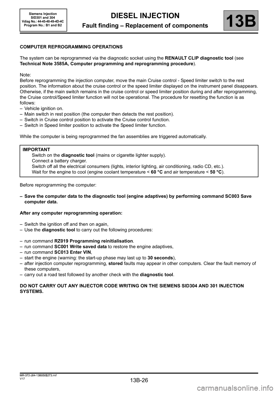
COMPUTER REPROGRAMMING OPERATIONS
The system can be reprogrammed via the diagnostic socket using the RENAULT CLIP diagnostic tool (see
Technical Note 3585A, Computer programming and reprogramming procedure).
Note:
Before reprogramming the injection computer, move the main Cruise control - Speed limiter switch to the rest
position. The information about the cruise control or the speed limiter displayed on the instrument panel disappears.
Otherwise, if the main switch remains in the cruise control or speed limiter position during and after reprogramming,
the Cruise control/Speed limiter function will not be operational. The procedure for resetting the function is as
follows:
– Vehicle ignition on.
– Main switch in rest position (the computer then detects the rest position).
– Switch in Cruise control position to activate the Cruise control function.
– Switch in Speed limiter position to activate the Speed limiter function.
While the computer is being reprogrammed the fan assemblies are triggered automatically.
Before reprogramming the computer:
– Save the computer data to the diagnostic tool (engine adaptives) by performing command SC003 Save
computer data.
After any computer reprogramming operation:
– Switch the ignition off and then on again,
–Use the diagnostic tool to carry out the following procedures:
– run command RZ019 Programming reinitialisation.
– run command SC001 Write saved data to restore the engine adaptives,
– run command SC013 Enter VIN,
– start the engine (warning: the start-up phase may last up to 30 seconds),
– after injection computer reprogramming, stored faults may appear in other computers. Clear the fault memory of
these computers,
– carry out a road test followed by another check with the diagnostic tool.
DO NOT CARRY OUT ANY INJECTOR CODE WRITING ON THE SIEMENS SID304 AND 301 INJECTION
SYSTEMS.IMPORTANT
Switch on the diagnostic tool (mains or cigarette lighter supply).
Connect a battery charger.
Switch off all the electrical consumers (lights, interior lighting, air conditioning, radio CD, etc.).
Wait for the engine to cool (engine coolant temperature < 60 °C and air temperature < 50 °C).
MR-372-J84-13B050$273.mif
Siemens Injection
SID301 and 304
Vdiag No.: 44-45-48-49-4D-4CProgram No.: B1 and B2
Page 27 of 329

13B-27
MR-372-J84-13B050$273.mif
V17
Siemens Injection
SID301 and 304
Vdiag No.: 44-45-48-49-4D-4C
Program No.: B1 and B2DIESEL INJECTION
Fault finding – Replacement of components13B
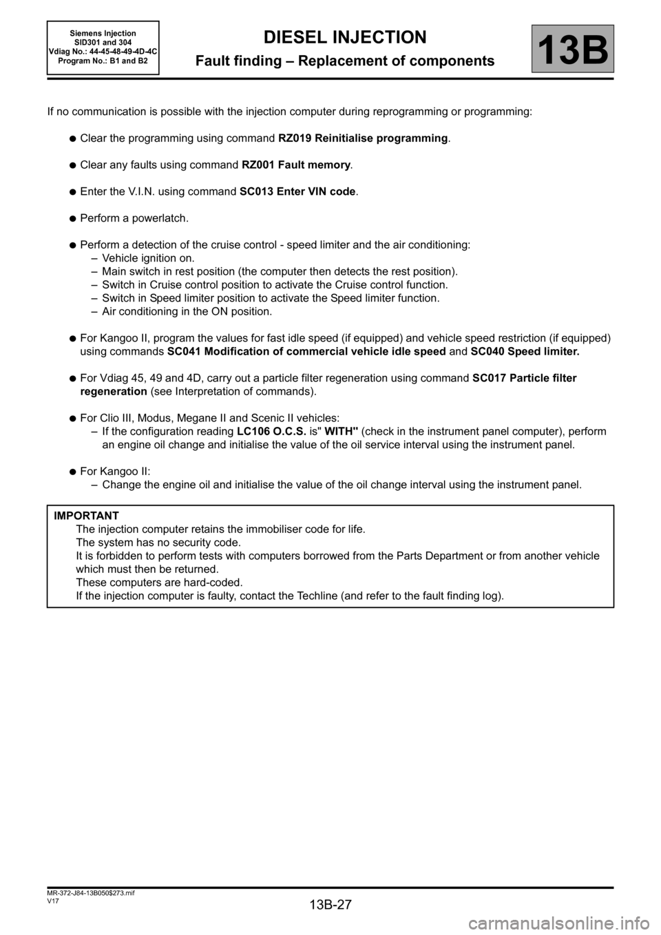
If no communication is possible with the injection computer during reprogramming or programming:
●Clear the programming using command RZ019 Reinitialise programming.
●Clear any faults using command RZ001 Fault memory.
●Enter the V.I.N. using command SC013 Enter VIN code.
●Perform a powerlatch.
●Perform a detection of the cruise control - speed limiter and the air conditioning:
– Vehicle ignition on.
– Main switch in rest position (the computer then detects the rest position).
– Switch in Cruise control position to activate the Cruise control function.
– Switch in Speed limiter position to activate the Speed limiter function.
– Air conditioning in the ON position.
●For Kangoo II, program the values for fast idle speed (if equipped) and vehicle speed restriction (if equipped)
using commands SC041 Modification of commercial vehicle idle speed and SC040 Speed limiter.
●For Vdiag 45, 49 and 4D, carry out a particle filter regeneration using command SC017 Particle filter
regeneration (see Interpretation of commands).
●For Clio III, Modus, Megane II and Scenic II vehicles:
– If the configuration reading LC106 O.C.S. is" WITH" (check in the instrument panel computer), perform
an engine oil change and initialise the value of the oil service interval using the instrument panel.
●For Kangoo II:
– Change the engine oil and initialise the value of the oil change interval using the instrument panel.
IMPORTANT
The injection computer retains the immobiliser code for life.
The system has no security code.
It is forbidden to perform tests with computers borrowed from the Parts Department or from another vehicle
which must then be returned.
These computers are hard-coded.
If the injection computer is faulty, contact the Techline (and refer to the fault finding log).
Page 28 of 329

13B-28
MR-372-J84-13B050$273.mif
V17
Siemens Injection
SID301 and 304
Vdiag No.: 44-45-48-49-4D-4C
Program No.: B1 and B2DIESEL INJECTION
Fault finding – Replacement of components13B
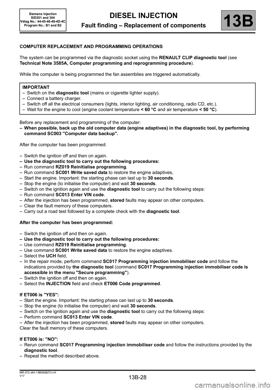
COMPUTER REPLACEMENT AND PROGRAMMING OPERATIONS
The system can be programmed via the diagnostic socket using the RENAULT CLIP diagnostic tool (see
Technical Note 3585A, Computer programming and reprogramming procedure).
While the computer is being programmed the fan assemblies are triggered automatically.
Before any replacement and programming of the computer:
– When possible, back up the old computer data (engine adaptives) in the diagnostic tool, by performing
command SC003 "Computer data backup".
After the computer has been programmed:
– Switch the ignition off and then on again.
– Use the diagnostic tool to carry out the following procedures:
– Run command RZ019 Reinitialise programming.
– Run command SC001 Write saved data to restore the engine adaptives,
– Start the engine. Important: the starting phase can last up to 30 seconds.
– Stop the engine (to initialise the computer) and wait 30 seconds.
– Switch on the ignition again and use the diagnostic tool to carry out the following steps:
– Run command SC013 Enter VIN code.
– After the injection has been programmed, stored faults may appear on other computers.
– Clear the fault memory of these computers.
– Carry out a road test followed by a complete check with the diagnostic tool.
After the computer has been programmed:
– Switch the ignition off and then on again.
– Use the diagnostic tool to carry out the following procedures:
– Use command RZ019 Reinitialise programming.
– Use command SC001 Write saved data to restore the engine adaptives.
– Select the UCH field,
– In the repair mode, perform command SC017 Programming injection immobiliser code and follow the
indications provided by the diagnostic tool (command SC017 Programming injection immobiliser code is
accessible in the menu "Secure programming").
– Switch the ignition off and then on again.
– Select the INJECTION field and check ET006 Code programmed.
If ET006 is "YES":
– Start the engine. Important: the starting phase can last up to 30 seconds.
– Stop the engine (to initialise the computer) and wait 30 seconds.
– Switch on the ignition again and use the diagnostic tool to carry out the following steps:
– Perform command SC013 Enter VIN code.
– After the injection has been programmed, stored faults may appear on other computers.
Clear the fault memory of these computers.
If ET006 is: "NO":
– Rerun command SC017 Programming injection immobiliser code and follow the instructions provided by the
diagnostic tool.
– Repeat the method described above.IMPORTANT
– Switch on the diagnostic tool (mains or cigarette lighter supply).
– Connect a battery charger.
– Switch off all the electrical consumers (lights, interior lighting, air conditioning, radio CD, etc.).
– Wait for the engine to cool (engine coolant temperature < 60 °C and air temperature < 50 °C).
Page 30 of 329

13B-30
MR-372-J84-13B050$312.mif
V17
13B
DIESEL INJECTION
Fault finding – Configurations and programming
SPECIAL COMMANDS
SC001: Write saved data.
Use this command after replacing or (re)programming the computer (if the data has been saved using command
SC003).
SC003: Save computer data.
This command enables the computer operating data, the engine adaptives, to be recorded.
Use this command before replacing or (re)programming a computer.
SC013: Enter VIN.
This command permits manual entry of the vehicle's VIN into the computer.
Use this command each time the computer is replaced or (re)programmed.
SC017: Particle filter regeneration.
The regeneration command is used to burn particles which have accumulated in the filter.
Run this command when the particle filter is clogged.
SC040: Speed limiter (Kangoo II only).
This command enables the vehicle's speed to be restricted to a certain speed.
Use this command at the customer's request.
SC041: Modification of the commercial vehicle idle speed (Kangoo II only).
This command enables the idle speed for vehicles such as refrigerated vehicles, ambulances etc. to be increased or
decreased.
CONFIGURATION READING
LC005: Gearbox type.
Manual gearbox or automatic transmission/sequential gearbox
LC009: Air conditioning.
With or without.
LC065: Water in diesel fuel sensor.
With or without.
LC120: Cruise control.
With or without.
LC121: Speed limiter.
With or without.
MR-372-J84-13B050$312.mif
Siemens Injection
SID301 and 304
Vdiag No.: 44-45-48-49-4D-4C
Program No.: B1 and B2
Page 35 of 329

13B-35
MR-372-J84-13B050$390.mif
V17
13B
DIESEL INJECTION
Fault finding – Interpretation of faults
DF001
PRESENT
OR
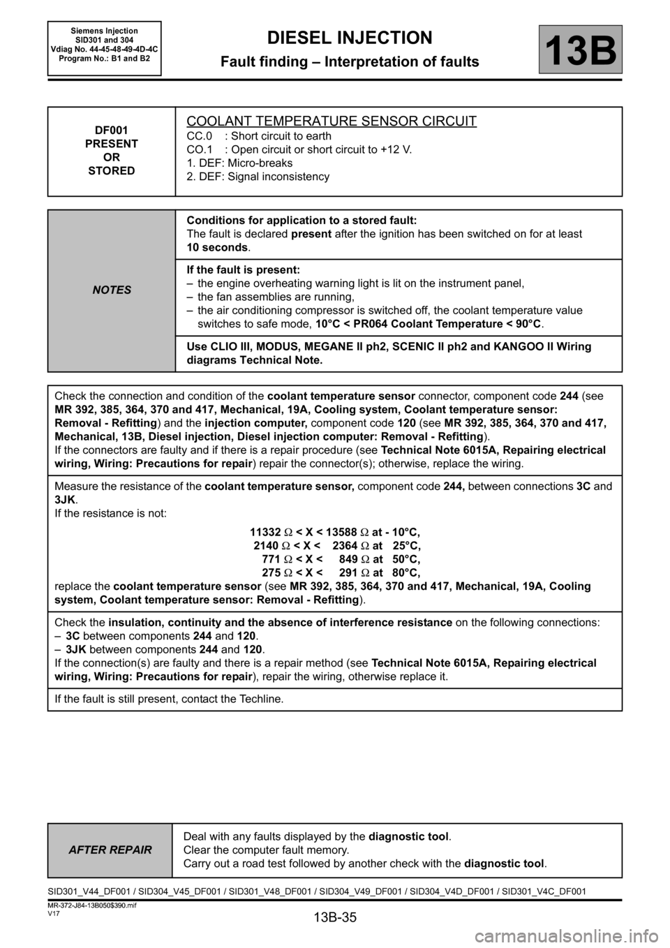
STOREDCOOLANT TEMPERATURE SENSOR CIRCUIT
CC.0 : Short circuit to earth
CO.1 : Open circuit or short circuit to +12 V.
1. DEF: Micro-breaks
2. DEF: Signal inconsistency
NOTESConditions for application to a stored fault:
The fault is declared present after the ignition has been switched on for at least
10 seconds.
If the fault is present:
– the engine overheating warning light is lit on the instrument panel,
– the fan assemblies are running,
– the air conditioning compressor is switched off, the coolant temperature value
switches to safe mode, 10°C < PR064 Coolant Temperature < 90°C.
Use CLIO III, MODUS, MEGANE II ph2, SCENIC II ph2 and KANGOO II Wiring
diagrams Technical Note.
Check the connection and condition of the coolant temperature sensor connector, component code244 (see
MR 392, 385, 364, 370 and 417, Mechanical, 19A, Cooling system, Coolant temperature sensor:
Removal - Refitting) and the injection computer, component code120 (see MR 392, 385, 364, 370 and 417,
Mechanical, 13B, Diesel injection, Diesel injection computer: Removal - Refitting).
If the connectors are faulty and if there is a repair procedure (see Technical Note 6015A, Repairing electrical
wiring, Wiring: Precautions for repair) repair the connector(s); otherwise, replace the wiring.
Measure the resistance of the coolant temperature sensor, component code 244, between connections 3C and
3JK.
If the resistance is not:
11332Ω < X < 13588Ω at - 10°C,
2140Ω < X < 2364Ω at 25°C,
771Ω < X < 849Ω at 50°C,
275Ω < X < 291Ω at 80°C,
replace the coolant temperature sensor (see MR 392, 385, 364, 370 and 417, Mechanical, 19A, Cooling
system, Coolant temperature sensor: Removal - Refitting).
Check the insulation, continuity and the absence of interference resistance on the following connections:
–3C between components 244 and 120.
–3JK between components 244 and 120.
If the connection(s) are faulty and there is a repair method (see Technical Note 6015A, Repairing electrical
wiring, Wiring: Precautions for repair), repair the wiring, otherwise replace it.
If the fault is still present, contact the Techline.
AFTER REPAIRDeal with any faults displayed by the diagnostic tool.
Clear the computer fault memory.
Carry out a road test followed by another check with the diagnostic tool.
SID301_V44_DF001 / SID304_V45_DF001 / SID301_V48_DF001 / SID304_V49_DF001 / SID304_V4D_DF001 / SID301_V4C_DF001
MR-372-J84-13B050$390.mif
Siemens Injection
SID301 and 304
Vdiag No. 44-45-48-49-4D-4C
Program No.: B1 and B2
Page 36 of 329

13B-36
MR-372-J84-13B050$390.mif
V17
DIESEL INJECTION
Fault finding – Interpretation of faults
Siemens Injection
SID301 and 304
Vdiag No. 44-45-48-49-4D-4C
Program No.: B1 and B2
13B
DF003
PRESENT
OR
STOREDATMOSPHERIC PRESSURE SENSOR CIRCUIT
CC.1 : Short circuit to + 12 V
CO.0 : Open circuit or short circuit to earth
1. DEF: Micro-breaks
NOTESConditions for application to a stored fault:
The fault is declared present after the ignition has been switched on for at least
10 seconds.
If the fault is present:
– the OBD warning light is lit,
– small amount of smoke may be present,
– the atmospheric pressure value changes to safe mode, PR035 Atmospheric
pressure = 900 mbar.
Special notes:
The atmospheric pressure sensor is integrated into the injection computer and
cannot be separated.
Disconnect the injection computer, component code 120, and check the condition of the contacts and the
condition of its connector (see MR 392, 385, 364, 370 and 417, Mechanical, 13B, Diesel injection, Diesel
injection computer: Removal - Refitting).
If the connector is faulty and there is a repair procedure (see Technical Note 6015A, Electrical wiring repair,
Wiring: Precautions for repair), repair the connector, otherwise replace the wiring.
If the fault is still present, contact the Techline.
AFTER REPAIRDeal with any faults displayed by the diagnostic tool.
Clear the computer fault memory.
Carry out a road test followed by another check with the diagnostic tool.
SID301_V44_DF003 / SID304_V45_DF003 / SID301_V48_DF003 / SID304_V49_DF003 / SID304_V4D_DF003 / SID301_V4C_DF003
Page 37 of 329

13B-37
MR-372-J84-13B050$390.mif
V17
DIESEL INJECTION
Fault finding – Interpretation of faults
Siemens Injection
SID301 and 304
Vdiag No. 44-45-48-49-4D-4C
Program No.: B1 and B2
13B
DF004
PRESENT
OR
STORED
TURBOCHARGING PRESSURE SENSOR CIRCUIT
CC.1 : Short circuit to + 12 V
CO.0 : Open circuit or short circuit to earth
1. DEF: Micro-breaks
2. DEF: Signal outside lower limit
3. DEF: Signal outside upper limit
NOTESIf the fault is present:
– the Level 1 warning light is lit, the OBD warning light is lit, loss of performance.
CC.1
CO.0
1.DEF
NOTESPriority when dealing with a number of faults:
First apply the procedure for dealing with the fault DF012
Sensor supply voltage no. 2.
Conditions for application to a stored fault:
The fault is declared present after the ignition has been
switched on.
If the fault is present:
– the EGR function is inhibited,
– the turbocharging pressure value is in safe mode, PR041
Turbocharging pressure sensor = 1000 mbar,
– turbocharging is cut off.
Use CLIO III, MODUS, MEGANE II ph2, SCENIC II ph2 and
KANGOO II Wiring diagrams Technical Note.
Check the connection and condition of the turbocharging pressure sensor connector, component code1071
and the injection computer, component code120 (see MR 392, 385, 364, 370 and 417, Mechanical, 13B,
Diesel injection, Diesel injection computer: Removal - Refitting).
If the connectors are faulty and if there is a repair procedure (see Technical Note 6015A, Repairing electrical
wiring, Wiring: Precautions for repair) repair the connector(s); otherwise, replace the wiring.
With the ignition on, check for the presence of + 5 V on connection 3LQ and check for an earth on connection
3LN on the turbocharging pressure sensor, component code 1071.
If the connection(s) are faulty and there is a repair method (see Technical Note 6015A, Repairing electrical
wiring, Wiring: Precautions for repair), repair the wiring, otherwise replace it.
Check the insulation, continuity and the absence of interference resistance on the following connections:
–3LQ between components 1071 and 120,
–3LP between components 1071 and 120,
–3LN between components 1071 and 120.
If the connection(s) are faulty and there is a repair method (see Technical Note 6015A, Repairing electrical
wiring, Wiring: Precautions for repair), repair the wiring, otherwise replace it.
If the fault is still present, replace the turbocharging pressure sensor.
AFTER REPAIRDeal with any faults displayed by the diagnostic tool.
Clear the computer fault memory.
Carry out a road test followed by another check with the diagnostic tool.
SID301_V44_DF004 / SID304_V45_DF004 / SID301_V48_DF004 / SID304_V49_DF004 / SID304_V4D_DF004 / SID301_V4C_DF004