2011 RENAULT SCENIC charging
[x] Cancel search: chargingPage 314 of 431

13B-314V9 MR-372-J84-13B450$152.mif
DIESEL INJECTION
Fault finding – Interpretation of parameters13B
PR209TURBOCHARGING PRESSURE LOOP DIFFERENCE
PARAMETER
DEFINITIONThis parameter indicates the turbocharging pressure loop difference in bar.
NOTESSpecial notes:
Only perform these tests if the parameters do not correspond with the system
operation programming.
Conformity check with engine running, engine coolant temperature > 80°C
PR209 = PR009 – PR041 = ~ 0
If PR209 is significant, apply the interpretation of command AC004 Turbocharging solenoid valve.
EDC16C36_V44_PR209/EDC16C36_V4C_PR209/EDC16C36_V48_PR209/EDC16C36_V50_PR209/EDC16C36_V54_PR209/
EDC16C36_V58_PR209
AFTER REPAIRCarry out a road test, then check with the diagnostic tool.
EDC16 C36
Program No.: 91
Vdiag No.: 44, 4C, 48,
50, 54, 58
Page 315 of 431

13B-315V9 MR-372-J84-13B450$152.mif
DIESEL INJECTION
Fault finding – Interpretation of parameters13B
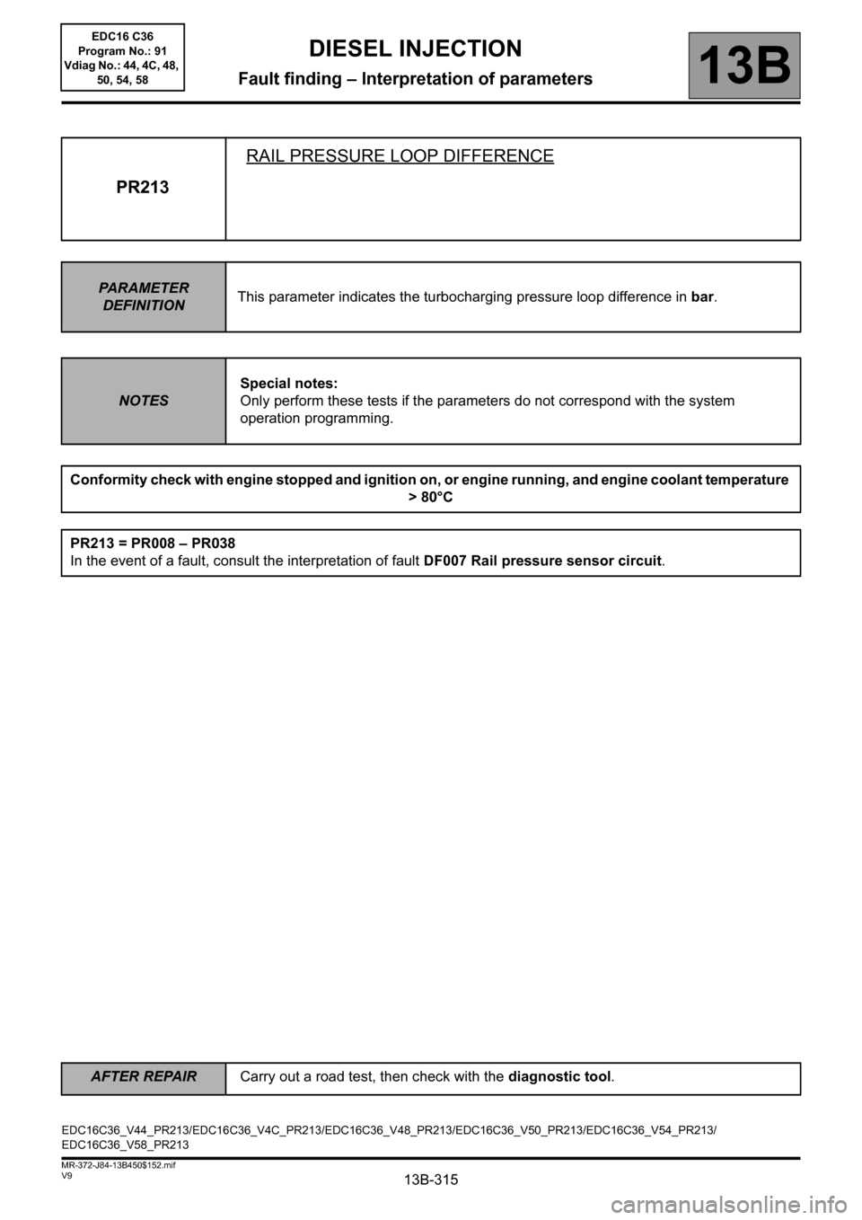
PR213RAIL PRESSURE LOOP DIFFERENCE
PARAMETER
DEFINITIONThis parameter indicates the turbocharging pressure loop difference in bar.
NOTESSpecial notes:
Only perform these tests if the parameters do not correspond with the system
operation programming.
Conformity check with engine stopped and ignition on, or engine running, and engine coolant temperature
> 80°C
PR213 = PR008 – PR038
In the event of a fault, consult the interpretation of fault DF007 Rail pressure sensor circuit.
EDC16C36_V44_PR213/EDC16C36_V4C_PR213/EDC16C36_V48_PR213/EDC16C36_V50_PR213/EDC16C36_V54_PR213/
EDC16C36_V58_PR213
AFTER REPAIRCarry out a road test, then check with the diagnostic tool.
EDC16 C36
Program No.: 91
Vdiag No.: 44, 4C, 48,
50, 54, 58
Page 316 of 431

13B-316V9 MR-372-J84-13B450$152.mif
DIESEL INJECTION
Fault finding – Interpretation of parameters13B
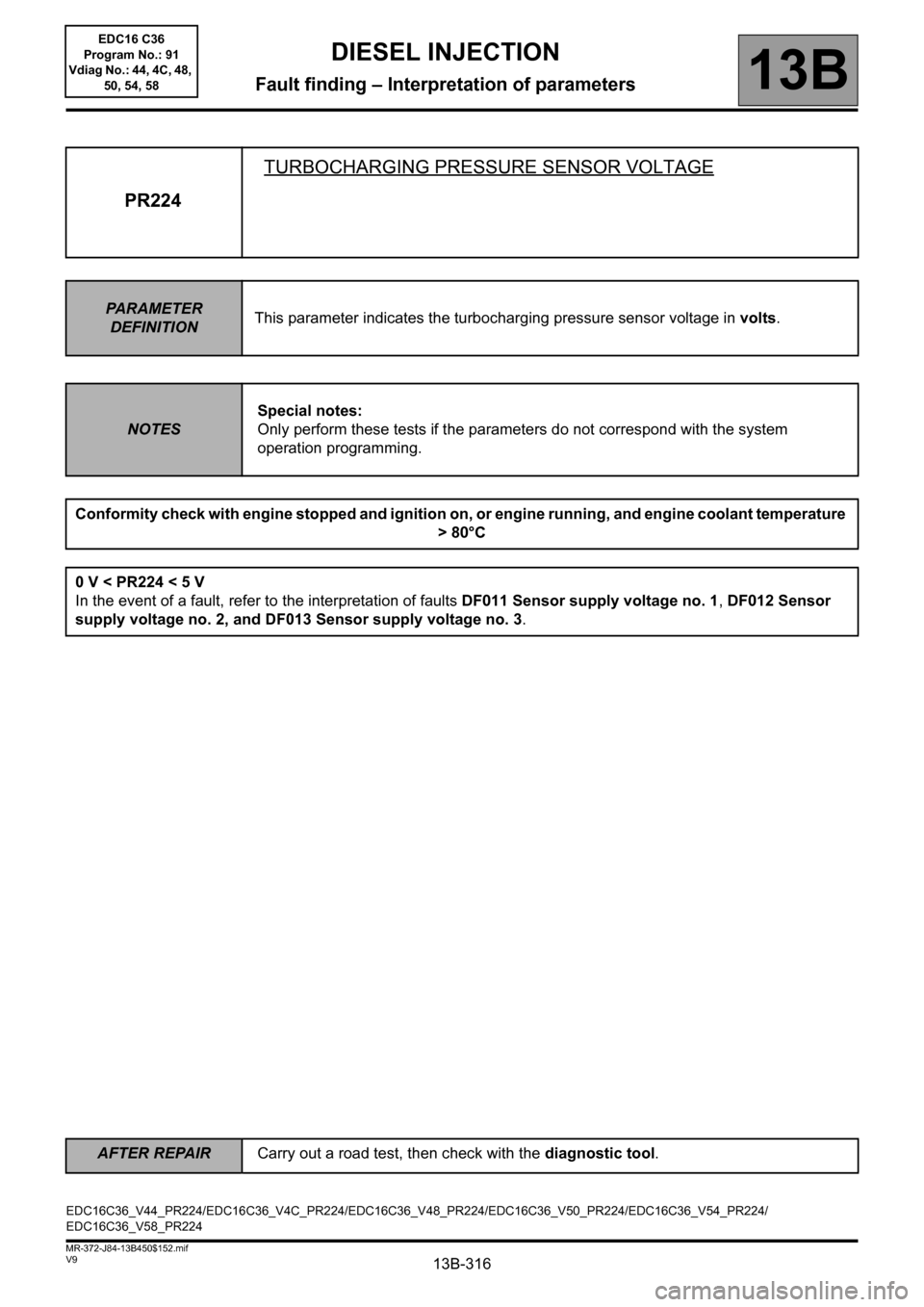
PR224TURBOCHARGING PRESSURE SENSOR VOLTAGE
PARAMETER
DEFINITIONThis parameter indicates the turbocharging pressure sensor voltage in volts.
NOTESSpecial notes:
Only perform these tests if the parameters do not correspond with the system
operation programming.
Conformity check with engine stopped and ignition on, or engine running, and engine coolant temperature
> 80°C
0 V < PR224 < 5 V
In the event of a fault, refer to the interpretation of faults DF011 Sensor supply voltage no. 1, DF012 Sensor
supply voltage no. 2, and DF013 Sensor supply voltage no. 3.
EDC16C36_V44_PR224/EDC16C36_V4C_PR224/EDC16C36_V48_PR224/EDC16C36_V50_PR224/EDC16C36_V54_PR224/
EDC16C36_V58_PR224
AFTER REPAIRCarry out a road test, then check with the diagnostic tool.
EDC16 C36
Program No.: 91
Vdiag No.: 44, 4C, 48,
50, 54, 58
Page 350 of 431

13B-350V9 MR-372-J84-13B450$160.mif
13B
EDC16 C36
Program No.: 91
Vdiag No.: 44, 4C, 48,
50, 54, 58
Tool
commandDiagnostic tool title comments
SC001Write saved data See Interpretation of commands.
SC002Enter injector codes See Interpretation of commands.
SC003Save computer data See Interpretation of commands.
SC017Particle filter regeneration See Interpretation of commands.
SC031Operational fault finding of cylinders See Interpretation of commands.
SC035High pressure fuel circuit fault finding See Interpretation of commands.
SC036Reinitialise programming See Interpretation of commands.
RZ001Fault memory See Interpretation of commands.
RZ005Programming See Interpretation of commands.
RZ034Computer memory See Interpretation of commands.
LC009Air conditioning See configuration and programming.
LC056Heating elements See configuration and programming.
LC065Water in diesel fuel sensor See configuration and programming.
LC120Cruise control See configuration and programming.
LC121Speed limiter See configuration and programming.
AC004Turbocharging solenoid valve See Interpretation of commands.
AC011Rail pressure regulator See Interpretation of commands.
AC012Damper valve See Interpretation of commands.
AC037Preheating relay See Interpretation of commands.
AC038Low speed GMV relay See Interpretation of commands.
AC039High speed GMV relay See Interpretation of commands.
AC103EGR by-pass See Interpretation of commands.
AC231Richness ratio sensor heating See Interpretation of commands.
VP010Write VIN See Interpretation of commands.
VP036Fuel supply inhibited See
Interpretation of commands.
VP037Lift fuel supply inhibition See Interpretation of commands.
DIESEL INJECTION
Fault finding – Command summary table
Page 367 of 431

13B-367
AFTER REPAIRRepeat the conformity check in the interpretation of statuses and parameters
V9 MR-372-J84-13B450$170.mif
DIESEL INJECTION
Fault finding – Interpretation of commands13B
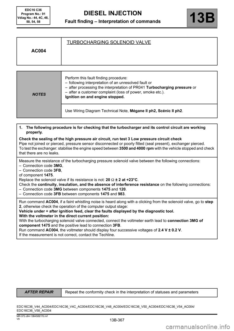
AC004TURBOCHARGING SOLENOID VALVE
NOTESPerform this fault finding procedure:
– following interpretation of an unresolved fault or
– after processing the interpretation of PR041 Turbocharging pressure or
– after a customer complaint (loss of power, smoke etc.).
Ignition on and engine stopped.
Use Wiring Diagram Technical Note, Mégane II ph2, Scénic II ph2.
1. The following procedure is for checking that the turbocharger and its control circuit are working
properly.
Check the sealing of the high pressure air circuit, run test 3 Low pressure circuit check
Pipe not joined or pierced, pressure sensor disconnected or poorly fitted (seal present), exchanger pierced.
To test the exchanger: stabilise the engine speed between 3500 and 4000 rpm with the vehicle stopped and check
that there are no leaks.
Measure the resistance of the turbocharging pressure solenoid valve between the following connections:
– Connection code 3MG,
– Connection code 3FB,
of component 1475.
Replace the solenoid valve if its resistance is not: 20 Ω ± 2 at +23°C.
Check the continuity, insulation, and the absence of interference resistance on the following connections:
– Connection code 3MG between components 1475 and 120.
– Connection code 3FB between components 1475 and 983.
Run command AC004, if a faint whistling noise is heard along with a clicking from the solenoid valve, go to step
2, otherwise check the operation of the computer output stage:
Vehicle under + after ignition feed, clear the faults displayed by the diagnostic tool.
With the voltmeter in the direct current position:
With the turbocharging solenoid valve connected, connect the voltmeter earth lead to connection 3MG of
component 1475 and the positive lead to connection3FB.
Run command AC004, the voltmeter should display four successive voltages of 2.4 V ± 0.2 V.
If the measurement is not correct, contact the Techline.
EDC16C36_V44_AC004/EDC16C36_V4C_AC004/EDC16C36_V48_AC004/EDC16C36_V50_AC004/EDC16C36_V54_AC004/
EDC16C36_V58_AC004EDC16 C36
Program No.: 91
Vdiag No.: 44, 4C, 48,
50, 54, 58
Page 383 of 431

13B-383
AFTER REPAIRCarry out a road test followed by a complete check with the diagnostic tool.
V9 MR-372-J84-13B450$190.mif
DIESEL INJECTION
Fault finding – Fault Finding Chart13B
ALP2 Starting difficult (or impossible)
NOTESBefore analysing this customer complaint, check that there are no faults, and the
conformity (or otherwise) of the parameters and statuses, using the diagnostic
tool.
If the customer complaint is not eliminated, perform the following checks.
Is it difficult or impossible to start the engine?
PART A:
Check the engine earths.
If the engine speed is less than 200 rpm, refer to Technical Note 6014A, Checking the charging circuit, Starter
fault finding, Starter.
If an engine speed of 200 rpm is achieved with starter motor in operation, PR055 Engine speed.
If the engine speed shown on CLIP is zero and the engine is running, check the resistance of the engine speed
sensor between the following connections:
– Connection code 3BG,
– Connection code 3BL,
of component 149.
Replace the sensor if the resistance is not between 200 Ω and 270 Ω at 20°C.
Check the continuity and insulation of the following connections:
– Connection code 3BG,
– Connection code 3BL,
between components 120 and 149.
If any of the connections are faulty and there is a repair method (see Technical Note 6015A, Electrical wiring
repair, Wiring: precautions for repairs), repair the wiring; otherwise replace the wiring.
Check the conformity of the engine earths (oxidation, tightness, etc.).
Check the mounting and condition (overheating) of the sensor.
Replace if necessary.
Check the synchronisation of the camshaft sensors and the engine speed sensors with the display of ET238
Synchronisation. If synchronisation is not active, refer to the checks described in DF195 Camshaft/engine
speed consistency.
Check the fuel circuit for leaks using test 3 Low pressure circuit check.
If test 3: Low pressure circuit check is correct.
PART
B
Impossible
Difficult
EDC16C36_V44_ALP02/EDC16C36_V4C_ALP02/EDC16C36_V48_ALP02/EDC16C36_V50_ALP02/EDC16C36_V54_ALP02/
EDC16C36_V58_ALP02EDC16 C36
Program No.: 91
Vdiag No.: 44, 4C, 48,
50, 54, 58
Page 385 of 431

13B-385
AFTER REPAIRCarry out a road test followed by a complete check with the diagnostic tool.
V9 MR-372-J84-13B450$190.mif
DIESEL INJECTION
Fault finding – Fault Finding Chart13B
ALP2
CONTINUED 2
Is there diesel fuel in the fuel tank?Fill the tank with diesel fuel.
Bleed the low and high pressure diesel circuit.
Does the starter motor work properly?
Ensure that the engine speed reaches PR055
Engine speed > ~ 200 rpm with the starter in
operation, Consult Technical Note 6014A, Checking the
charging circuit, 16A, Starter fault finding,
Starter.
Using the diagnostic tool, check the conformity of the immobiliser: ET003 Immobiliser must be INACTIVE.
ET003 not
in order, or
immobiliser warning light
permanently onET003 correct
(immobiliser code
warning light off)
Consult the fault finding procedure for the
immobiliser.Continue the fault finding procedure with Part A
of this fault finding chart.
PART
B
NO
YES
NO
YES
EDC16 C36
Program No.: 91
Vdiag No.: 44, 4C, 48,
50, 54, 58
Page 391 of 431

13B-391
AFTER REPAIRCarry out a road test followed by a complete check with the diagnostic tool.
V9 MR-372-J84-13B450$190.mif
DIESEL INJECTION
Fault finding – Fault Finding Chart13B
ALP7 Rough idle
NOTESBefore analysing this customer complaint, check that there are no faults, and the
conformity (or otherwise) of the parameters and statuses, using the diagnostic
tool.
If the customer complaint is not eliminated, perform the following checks.
Check the sealing and condition of the inlet circuit by running Test 4 Turbocharged air circuit check.
Check the low pressure circuit
check the engine parameters:
– Check the update of the engine management computer calibration (last calibration).
– Check the conformity of the IMA codes (using the Identification screen on the Clip diagnostic tool).
– Check the charging circuit (see Technical Note 6014A Checking the charging circuit)
– To check the conformity of the engine speed signal, check:
– The wiring.
– The flywheel position and the condition of the flywheel teeth.
– The position and tightness of the engine speed sensor.
– Check the fuel flow correction from station to station, run Test 10 Poor injector operation.
Check the connections and wiring of the injectors.
Check the connections and wiring of the engine management computer to the injectors.
Repair if necessary.
A
EDC16C36_V44_ALP07/EDC16C36_V4C_ALP07/EDC16C36_V48_ALP07/EDC16C36_V50_ALP07/EDC16C36_V54_ALP07/
EDC16C36_V58_ALP07EDC16 C36
Program No.: 91
Vdiag No.: 44, 4C, 48,
50, 54, 58