Page 204 of 365

13B-204
MR-372-J84-13B200$540.mif
V13
EDC16
Program No: C1
Vdiag No: 18, 1C, 20,
50, 58, 5CDIESEL INJECTION
Fault finding – Interpretation of statuses13B
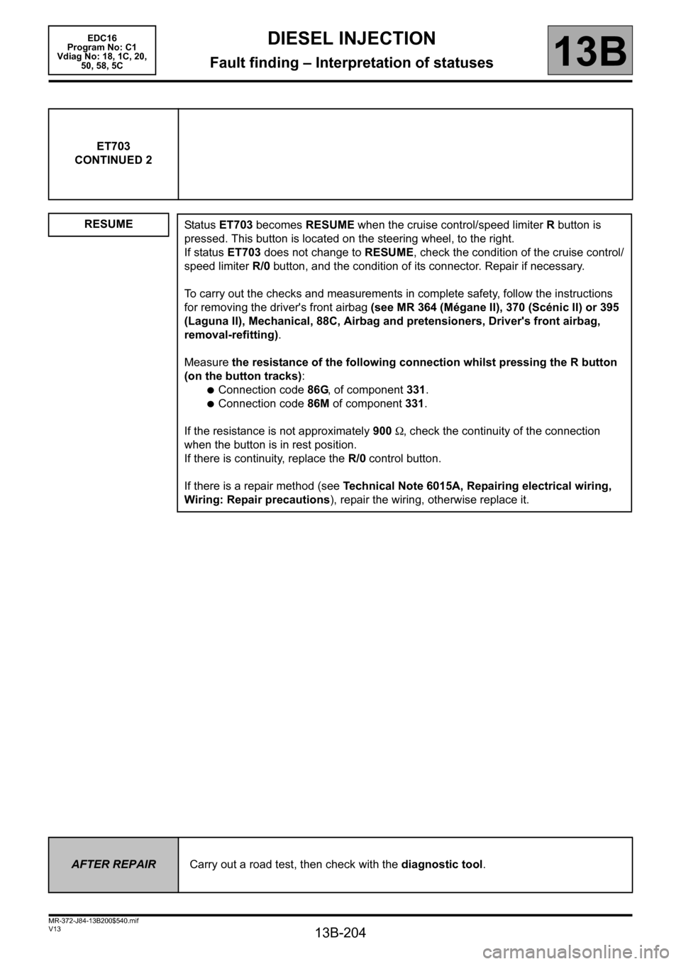
ET703
CONTINUED 2
RESUME
Status ET703 becomes RESUME when the cruise control/speed limiter R button is
pressed. This button is located on the steering wheel, to the right.
If status ET703 does not change to RESUME, check the condition of the cruise control/
speed limiter R/0 button, and the condition of its connector. Repair if necessary.
To carry out the checks and measurements in complete safety, follow the instructions
for removing the driver's front airbag (see MR 364 (Mégane II), 370 (Scénic II) or 395
(Laguna II), Mechanical, 88C, Airbag and pretensioners, Driver's front airbag,
removal-refitting).
Measure the resistance of the following connection whilst pressing the R button
(on the button tracks):
●Connection code86G, of component 331.
●Connection code 86M of component 331.
If the resistance is not approximately 900 Ω, check the continuity of the connection
when the button is in rest position.
If there is continuity, replace the R/0 control button.
If there is a repair method (see Technical Note 6015A, Repairing electrical wiring,
Wiring: Repair precautions), repair the wiring, otherwise replace it.
AFTER REPAIRCarry out a road test, then check with the diagnostic tool.
Page 293 of 365

13B-293
MR-372-J84-13B200$756.mif
V13
DIESEL INJECTION
Fault finding – Interpretation of commands
EDC16
Program No: C1
Vdiag No: 18, 1C, 20,
50, 58, 5C
13B
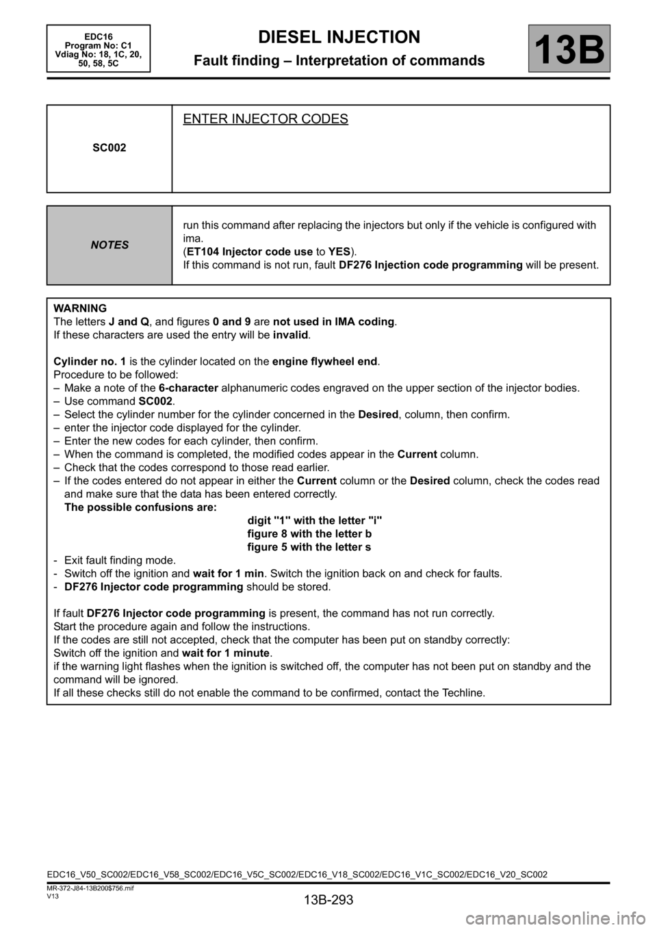
SC002
ENTER INJECTOR CODES
NOTESrun this command after replacing the injectors but only if the vehicle is configured with
ima.
(ET104 Injector code use to YES).
If this command is not run, fault DF276 Injection code programming will be present.
WARNING
The letters J and Q, and figures 0 and 9 are not used in IMA coding.
If these characters are used the entry will be invalid.
Cylinder no. 1 is the cylinder located on the engine flywheel end.
Procedure to be followed:
– Make a note of the 6-character alphanumeric codes engraved on the upper section of the injector bodies.
– Use command SC002.
– Select the cylinder number for the cylinder concerned in the Desired, column, then confirm.
– enter the injector code displayed for the cylinder.
– Enter the new codes for each cylinder, then confirm.
– When the command is completed, the modified codes appear in the Current column.
– Check that the codes correspond to those read earlier.
– If the codes entered do not appear in either the Current column or the Desired column, check the codes read
and make sure that the data has been entered correctly.
The possible confusions are:
digit "1" with the letter "i"
figure 8 with the letter b
figure 5 with the letter s
- Exit fault finding mode.
- Switch off the ignition and wait for 1 min. Switch the ignition back on and check for faults.
-DF276 Injector code programming should be stored.
If fault DF276 Injector code programming is present, the command has not run correctly.
Start the procedure again and follow the instructions.
If the codes are still not accepted, check that the computer has been put on standby correctly:
Switch off the ignition and wait for 1 minute.
if the warning light flashes when the ignition is switched off, the computer has not been put on standby and the
command will be ignored.
If all these checks still do not enable the command to be confirmed, contact the Techline.
EDC16_V50_SC002/EDC16_V58_SC002/EDC16_V5C_SC002/EDC16_V18_SC002/EDC16_V1C_SC002/EDC16_V20_SC002
Page 324 of 365

13B-324
MR-372-J84-13B200$828.mif
V13
DIESEL INJECTION
Fault finding – Fault Finding Chart
EDC16
Program No.: C1
Vdiag no.: 18, 1C, 20,
50, 58, 5C
13B
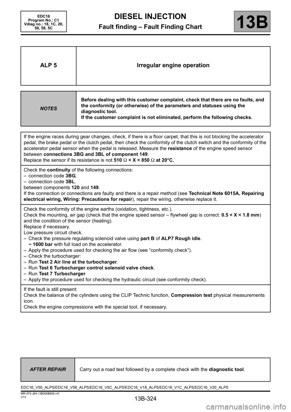
ALP 5 Irregular engine operation
NOTESBefore dealing with this customer complaint, check that there are no faults, and
the conformity (or otherwise) of the parameters and statuses using the
diagnostic tool.
If the customer complaint is not eliminated, perform the following checks.
If the engine races during gear changes, check, if there is a floor carpet, that this is not blocking the accelerator
pedal, the brake pedal or the clutch pedal, then check the conformity of the clutch switch and the conformity of the
accelerator pedal sensor when the pedal is released. Measure the resistance of the engine speed sensor
between connections 3BG and 3BL of component 149:
Replace the sensor if its resistance is not 510 Ω < X < 850 Ω at 20°C.
Check the continuity of the following connections:
– connection code 3BG,
– connection code 3BL.
between components 120 and 149.
If the connection or connections are faulty and there is a repair method (see Technical Note 6015A, Repairing
electrical wiring, Wiring: Precautions for repair), repair the wiring, otherwise replace it.
Check the conformity of the engine earths (oxidation, tightness, etc.).
Check the mounting, air gap (check that the engine speed sensor – flywheel gap is correct: 0.5 < X < 1.8 mm)
and the condition of the sensor (heating).
Replace if necessary.
Low pressure circuit check.
– Check the pressure regulating solenoid valve using part B of ALP7 Rough idle.
~ 1600 bar with full load on the accelerator.
– Apply the procedure used for checking the air flow (see “conformity check”).
– Check the turbocharger:
–Run Test 2 Air line at the turbocharger.
–Run Test 6 Turbocharger control solenoid valve check.
–Run Test 7 Turbocharger.
– Apply the procedure used for checking the hydraulic circuit (see conformity check).
If the fault is still present:
Check the balance of the cylinders using the CLIP Technic function, Compression test physical measurements
icon.
Check the engine compressions with the special tool, if necessary.
AFTER REPAIRCarry out a road test followed by a complete check with the diagnostic tool.
EDC16_V50_ALP5/EDC16_V58_ALP5/EDC16_V5C_ALP5/EDC16_V18_ALP5/EDC16_V1C_ALP5/EDC16_V20_ALP5
Page 327 of 365

13B-327
MR-372-J84-13B200$828.mif
V13
DIESEL INJECTION
Fault finding – Fault Finding Chart
EDC16
Program No.: C1
Vdiag no.: 18, 1C, 20,
50, 58, 5C
13B
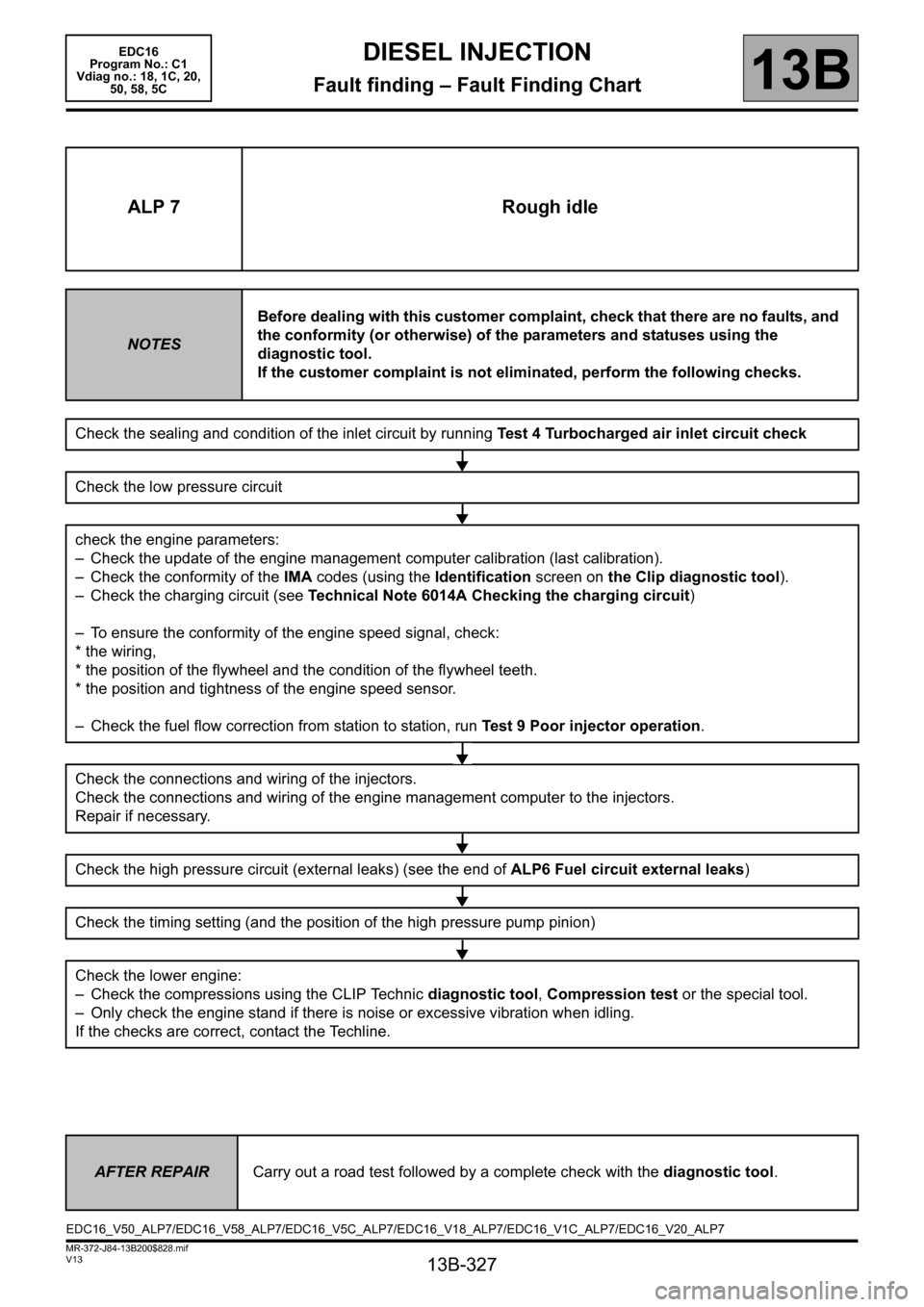
ALP 7 Rough idle
NOTESBefore dealing with this customer complaint, check that there are no faults, and
the conformity (or otherwise) of the parameters and statuses using the
diagnostic tool.
If the customer complaint is not eliminated, perform the following checks.
Check the sealing and condition of the inlet circuit by running Test 4 Turbocharged air inlet circuit check
Check the low pressure circuit
check the engine parameters:
– Check the update of the engine management computer calibration (last calibration).
– Check the conformity of the IMA codes (using the Identification screen on the Clip diagnostic tool).
– Check the charging circuit (see Technical Note 6014A Checking the charging circuit)
– To ensure the conformity of the engine speed signal, check:
* the wiring,
* the position of the flywheel and the condition of the flywheel teeth.
* the position and tightness of the engine speed sensor.
– Check the fuel flow correction from station to station, run Test 9 Poor injector operation.
Check the connections and wiring of the injectors.
Check the connections and wiring of the engine management computer to the injectors.
Repair if necessary.
Check the high pressure circuit (external leaks) (see the end of ALP6 Fuel circuit external leaks)
Check the timing setting (and the position of the high pressure pump pinion)
Check the lower engine:
– Check the compressions using the CLIP Technic diagnostic tool, Compression test or the special tool.
– Only check the engine stand if there is noise or excessive vibration when idling.
If the checks are correct, contact the Techline.
AFTER REPAIRCarry out a road test followed by a complete check with the diagnostic tool.
EDC16_V50_ALP7/EDC16_V58_ALP7/EDC16_V5C_ALP7/EDC16_V18_ALP7/EDC16_V1C_ALP7/EDC16_V20_ALP7