Page 275 of 365
13B-275
MR-372-J84-13B200$684.mif
V13
DIESEL INJECTION
Fault finding – Interpretation of parameters
EDC16
Program No: C1
Vdiag No: 18, 1C, 20,
50, 58, 5C
13B
PR406
CYLINDER NO. 3 FUEL FLOW CORRECTION
PARAMETER
DEFINITIONThis parameter indicates the cylinder's fuel flow correction in mg/stroke.
NOTESSpecial notes:
Only perform these tests if the parameters do not correspond with the system
operation programming.
Conformity check with engine stopped and ignition on.
PR406 = 0.0 mg/st.
In the event of a fault, consult test 9 Poor injector operation.
Conformity check with engine running, engine coolant temperature > 80 °C.
PR406 = ≈ 1 mg/stroke
In the event of a fault, consult test 9 Poor injector operation.
AFTER REPAIRCarry out a road test, then check with the diagnostic tool.
EDC16_V50_PR406/EDC16_V58_PR406/EDC16_V5C_PR406/EDC16_V18_PR406/EDC16_V1C_PR406/EDC16_V20_PR406
Page 327 of 365
13B-327
MR-372-J84-13B200$828.mif
V13
DIESEL INJECTION
Fault finding – Fault Finding Chart
EDC16
Program No.: C1
Vdiag no.: 18, 1C, 20,
50, 58, 5C
13B
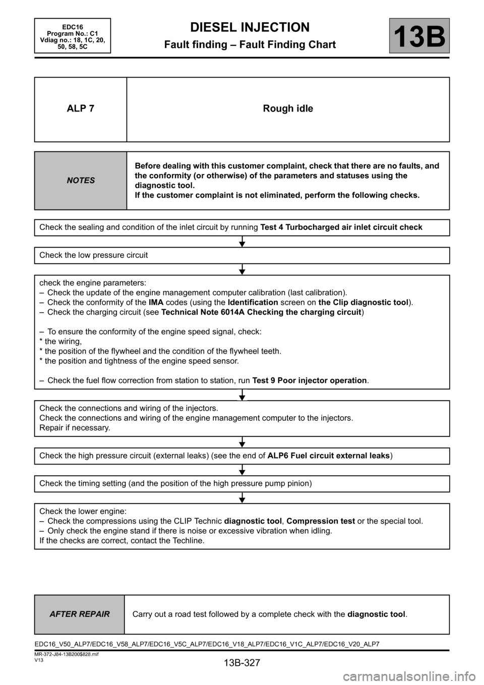
ALP 7 Rough idle
NOTESBefore dealing with this customer complaint, check that there are no faults, and
the conformity (or otherwise) of the parameters and statuses using the
diagnostic tool.
If the customer complaint is not eliminated, perform the following checks.
Check the sealing and condition of the inlet circuit by running Test 4 Turbocharged air inlet circuit check
Check the low pressure circuit
check the engine parameters:
– Check the update of the engine management computer calibration (last calibration).
– Check the conformity of the IMA codes (using the Identification screen on the Clip diagnostic tool).
– Check the charging circuit (see Technical Note 6014A Checking the charging circuit)
– To ensure the conformity of the engine speed signal, check:
* the wiring,
* the position of the flywheel and the condition of the flywheel teeth.
* the position and tightness of the engine speed sensor.
– Check the fuel flow correction from station to station, run Test 9 Poor injector operation.
Check the connections and wiring of the injectors.
Check the connections and wiring of the engine management computer to the injectors.
Repair if necessary.
Check the high pressure circuit (external leaks) (see the end of ALP6 Fuel circuit external leaks)
Check the timing setting (and the position of the high pressure pump pinion)
Check the lower engine:
– Check the compressions using the CLIP Technic diagnostic tool, Compression test or the special tool.
– Only check the engine stand if there is noise or excessive vibration when idling.
If the checks are correct, contact the Techline.
AFTER REPAIRCarry out a road test followed by a complete check with the diagnostic tool.
EDC16_V50_ALP7/EDC16_V58_ALP7/EDC16_V5C_ALP7/EDC16_V18_ALP7/EDC16_V1C_ALP7/EDC16_V20_ALP7
Page 350 of 365

13B-350
MR-372-J84-13B200$936.mif
V13
DIESEL INJECTION
Fault finding – Tests
EDC16
Program No: C1
Vdiag No: 18, 1C, 20,
50, 58, 5C
13B
TEST 9 Incorrect injector operation
Section A: Fuel regulation balance check for each injector (individual correction):
– In the CLIP diagnostic tool, choose the Fuel circuit subfunction.
– With the engine idling and the fuel temperature > 50°C, display the flow correction values for each injector
(individual correction), i.e.:
– PR364 Cylinder no. 1 fuel flow correction.
– PR405 Cylinder no. 2 fuel flow correction.
– PR406 Cylinder no. 3 fuel flow correction.
– PR365 Cylinder no. 4 fuel flow correction.
The flow correction range per injector is between - 5 mg/stroke and + 5 mg/stroke without reaching these
values.
– If this has not already been carried out, check the injector connections and wiring.
– Check the connections and wiring of the engine management computer to the injectors.
– Repair if necessary.
– Check the IMA injector codes, comparing the IMA codes on the injectors (the IMA codes must be read from left
to right) and the IMA codes read in the CLIP diagnostic tool.
– If the IMA codes are correct, continue the fault finding procedure,
– If not, modify the incorrect IMA codes using command SC002 Enter injector codes (see Interpretation of
commands).
To confirm the repair, consult part B of test 9.
CASE No. 1: If at least one of these values is equal to or greater than + 5 mg/st
– Check the valve clearance.
– Check the condition of the engine and the compressions (using the Clip diagnostic tool or a compression
gauge).
– If the compression test reveals a cylinder fault, carry out the necessary repairs.
– If the compression is correct, check that the injector is fitted correctly (see MR 364 (Mégane II), 370 (Scénic II)
or 395 (Laguna II), Mechanical, 13B, Diesel injection, Diesel injector: Removal - Refitting)
In particular, check that each injector has one compression washer.
Check the fuel regulation again for each injector (individual correction).
– If not, replace the injector and check for the sealing washer. Modify the IMA code using command SC002 Enter
injector codes (see Interpretation of commands).
–Apply Part B of this test to confirm the fault finding.
EDC16_V50_TEST9/EDC16_V58_TEST9/EDC16_V5C_TEST9/EDC16_V18_TEST9/EDC16_V1C_TEST9/EDC16_V20_TEST9
Page 351 of 365
13B-351
MR-372-J84-13B200$936.mif
V13
DIESEL INJECTION
Fault finding – Tests
EDC16
Program No: C1
Vdiag No: 18, 1C, 20,
50, 58, 5C
13B
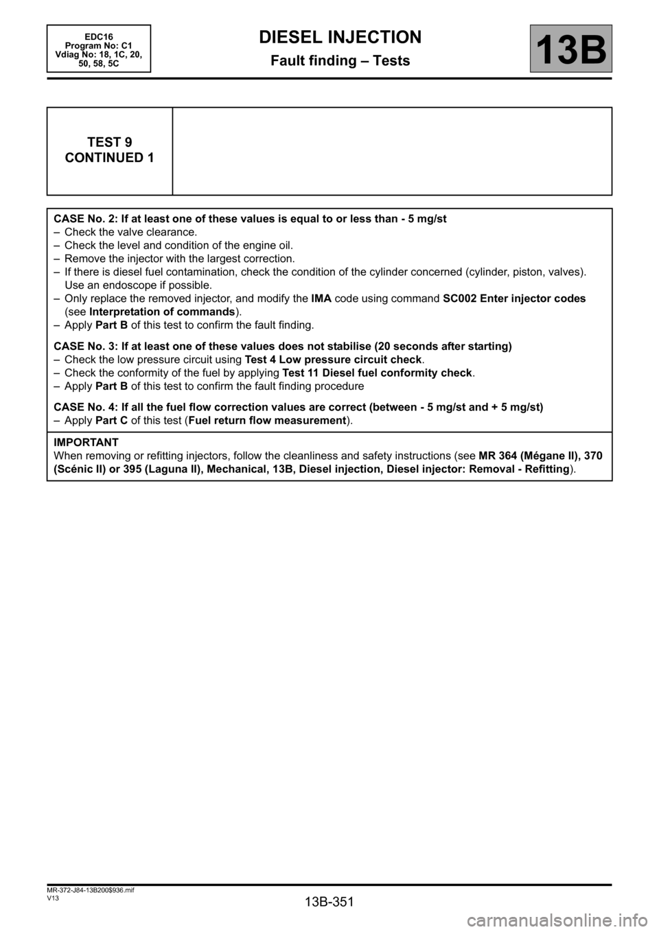
TEST 9
CONTINUED 1
CASE No. 2: If at least one of these values is equal to or less than - 5 mg/st
– Check the valve clearance.
– Check the level and condition of the engine oil.
– Remove the injector with the largest correction.
– If there is diesel fuel contamination, check the condition of the cylinder concerned (cylinder, piston, valves).
Use an endoscope if possible.
– Only replace the removed injector, and modify the IMA code using command SC002 Enter injector codes
(see Interpretation of commands).
–Apply Part B of this test to confirm the fault finding.
CASE No. 3: If at least one of these values does not stabilise (20 seconds after starting)
– Check the low pressure circuit using Test 4 Low pressure circuit check.
– Check the conformity of the fuel by applying Test 11 Diesel fuel conformity check.
–Apply Part B of this test to confirm the fault finding procedure
CASE No. 4: If all the fuel flow correction values are correct (between - 5 mg/st and + 5 mg/st)
–Apply Part C of this test (Fuel return flow measurement).
IMPORTANT
When removing or refitting injectors, follow the cleanliness and safety instructions (see MR 364 (Mégane II), 370
(Scénic II) or 395 (Laguna II), Mechanical, 13B, Diesel injection, Diesel injector: Removal - Refitting).
Page 352 of 365

13B-352
MR-372-J84-13B200$936.mif
V13
DIESEL INJECTION
Fault finding – Tests
EDC16
Program No: C1
Vdiag No: 18, 1C, 20,
50, 58, 5C
13B
TEST 9
CONTINUED 2
Section B: Confirmation of flow correction fault finding for each injector (individual correction):
Clear the faults and perform a test with the engine idling for at least 5 minutes and fuel temperature > 50°C.
Check that no fault appears on the CLIP diagnostic tool and that the corrective values do not reach ±5mg/
stroke to confirm the repair.
If the customer complaint is still present and the fuel flow correction values are between
-5 mg/stroke and + 5mg/stroke, apply Part A Fuel regulation balance check for each injector (individual)
of this test (Case no.4).
If one or more cylinders has an injector flow correction value in excess of ± 5 mg/stroke, apply Part A Fuel
regulation balance check for each injector (individual) of this test, as one or more injectors may be defective.
Part C: Measuring fuel return flow
1 – Fitting the tool:
This section is only to be carried out if PR063 "Fuel temperature" is higher than 50°C (see step 2 of
section C for this test).
Remove the engine undertray
Disconnect the entire fuel return pipe in accordance with the following procedure (do not remove the clips):
– press the clip,
– pull vertically on the end piece (see arrow in the diagram below) of the fuel return pipe.
IMPORTANT
The end piece is fragile. Be careful not to break it by pulling it too hard. Replace all removed clips
