Page 197 of 365

13B-197
MR-372-J84-13B200$540.mif
V13
EDC16
Program No: C1
Vdiag No: 18, 1C, 20,
50, 58, 5CDIESEL INJECTION
Fault finding – Interpretation of statuses13B
ET415
CONTINUED 2
STATUS 5
Cruise control or speed limiter monitoring
This status appears when the vehicle brakes or decelerates sharply without the
injection computer receiving a signal indicating that the brake pedal switch has been
pressed.
If status ET415 is STATUS 5, refer to the interpretation of:
– of status ET042 Cruise control/speed limiter,
– of status ET703 Cruise control/speed limiter buttons,
– of status ET704 Brake contact no. 1,
– and status ET705 Brake contact No 2,
to test the cruise control/speed limiter system components and find the defective
component.
Also check the operation of the accelerator pedal, and check for any faults on the
diagnostic tool relating to this component. Deal with them if necessary.
Reinitialise status ET415 on the injection computer by running command RZ007
"Fault memory".
If status ET415 changes to "STATUS 5", deal with present faults or those stored in the
injection computer.
If the fault is still present, contact Techline.
STATUS 6Gear lever in neutral (manual gearbox) or the neutral position (automatic
gearbox)
Status ET415 becomes STATUS 6 when driving with cruise control active (ET042
"Cruise control/speed limiter": CRUISE CONTROL) and:
– If the driver puts the gear lever in neutral position on a manual gearbox without
declutching or,
– if the gear lever is in neutral on an automatic gearbox.
This deactivates cruise control.
Reinitialise status ET415 on the injection computer by running command RZ007
"Fault memory".
If status ET415 becomes STATUS 6 without shifting the gear lever into neutral on a
manual gearbox without declutching, or into neutral on an automatic transmission, test
the ABS computer and check the configuration of the tyre size stored in the computer. If
the configuration is correct, contact the Techline.
AFTER REPAIRCarry out a road test, then check with the diagnostic tool.
Page 200 of 365

13B-200
MR-372-J84-13B200$540.mif
V13
EDC16
Program No: C1
Vdiag No: 18, 1C, 20,
50, 58, 5CDIESEL INJECTION
Fault finding – Interpretation of statuses13B
ET651
EGR PROGRAMMING CUT-OFF
STATUS DEFINITIONThis status indicates the EGR valve programming cut-off.
NOTESSpecial notes:
Only perform these tests if the status does not correspond with the system
programming functions.
Conformity check with engine stopped and ignition on, or engine running, and engine coolant
temperature > 80 °C
NONE
No EGR cut-off, the EGR valve is working properly in accordance with the
computer programs.
STATUS 1, 5, 6, 7, 9,
10, 12, 13, 15, 19
23, 24Switch off the ignition and wait 1 minute.
Switch the ignition on and check for faults.
Check the engine battery voltage with the engine switched off and the engine running.
If no faults are present or stored, restart the vehicle and test at idle speed.
Do not accelerate too much and reach an engine speed that is too high.
STATUS 3, 14, 16Accelerate above idle speed for a few seconds.
STATUS 2Check that the clutch pedal (ET405 "Clutch pedal switch") is not pressed and that the
vehicle has stopped completely.
STATUS 4, 17Test the present and stored faults and repair.
STATUS 8Reset the EGR offsets by referring to the interpretation of command SC036
"Reinitialise programming" and select "EGR valve".
AFTER REPAIRCarry out a road test, then check with the diagnostic tool.
EDC16_V50_ET651/EDC16_V58_ET651/EDC16_V5C_ET651/EDC16_V18_ET651/EDC16_V1C_ET651/EDC16_V20_ET651
Page 324 of 365

13B-324
MR-372-J84-13B200$828.mif
V13
DIESEL INJECTION
Fault finding – Fault Finding Chart
EDC16
Program No.: C1
Vdiag no.: 18, 1C, 20,
50, 58, 5C
13B
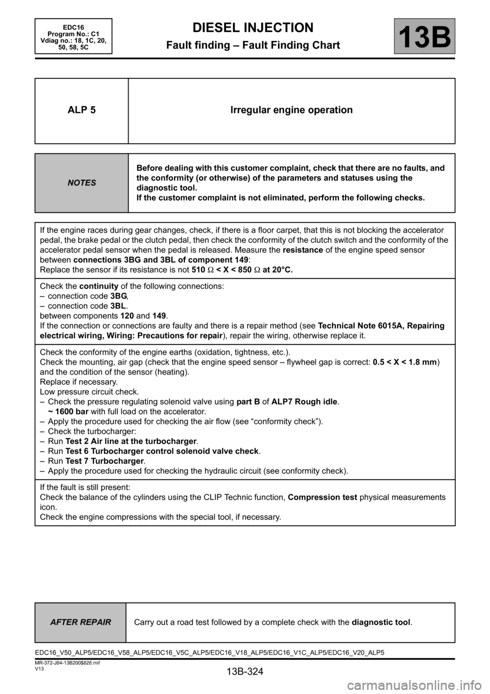
ALP 5 Irregular engine operation
NOTESBefore dealing with this customer complaint, check that there are no faults, and
the conformity (or otherwise) of the parameters and statuses using the
diagnostic tool.
If the customer complaint is not eliminated, perform the following checks.
If the engine races during gear changes, check, if there is a floor carpet, that this is not blocking the accelerator
pedal, the brake pedal or the clutch pedal, then check the conformity of the clutch switch and the conformity of the
accelerator pedal sensor when the pedal is released. Measure the resistance of the engine speed sensor
between connections 3BG and 3BL of component 149:
Replace the sensor if its resistance is not 510 Ω < X < 850 Ω at 20°C.
Check the continuity of the following connections:
– connection code 3BG,
– connection code 3BL.
between components 120 and 149.
If the connection or connections are faulty and there is a repair method (see Technical Note 6015A, Repairing
electrical wiring, Wiring: Precautions for repair), repair the wiring, otherwise replace it.
Check the conformity of the engine earths (oxidation, tightness, etc.).
Check the mounting, air gap (check that the engine speed sensor – flywheel gap is correct: 0.5 < X < 1.8 mm)
and the condition of the sensor (heating).
Replace if necessary.
Low pressure circuit check.
– Check the pressure regulating solenoid valve using part B of ALP7 Rough idle.
~ 1600 bar with full load on the accelerator.
– Apply the procedure used for checking the air flow (see “conformity check”).
– Check the turbocharger:
–Run Test 2 Air line at the turbocharger.
–Run Test 6 Turbocharger control solenoid valve check.
–Run Test 7 Turbocharger.
– Apply the procedure used for checking the hydraulic circuit (see conformity check).
If the fault is still present:
Check the balance of the cylinders using the CLIP Technic function, Compression test physical measurements
icon.
Check the engine compressions with the special tool, if necessary.
AFTER REPAIRCarry out a road test followed by a complete check with the diagnostic tool.
EDC16_V50_ALP5/EDC16_V58_ALP5/EDC16_V5C_ALP5/EDC16_V18_ALP5/EDC16_V1C_ALP5/EDC16_V20_ALP5