2011 RENAULT SCENIC air condition
[x] Cancel search: air conditionPage 324 of 365

13B-324
MR-372-J84-13B200$828.mif
V13
DIESEL INJECTION
Fault finding – Fault Finding Chart
EDC16
Program No.: C1
Vdiag no.: 18, 1C, 20,
50, 58, 5C
13B
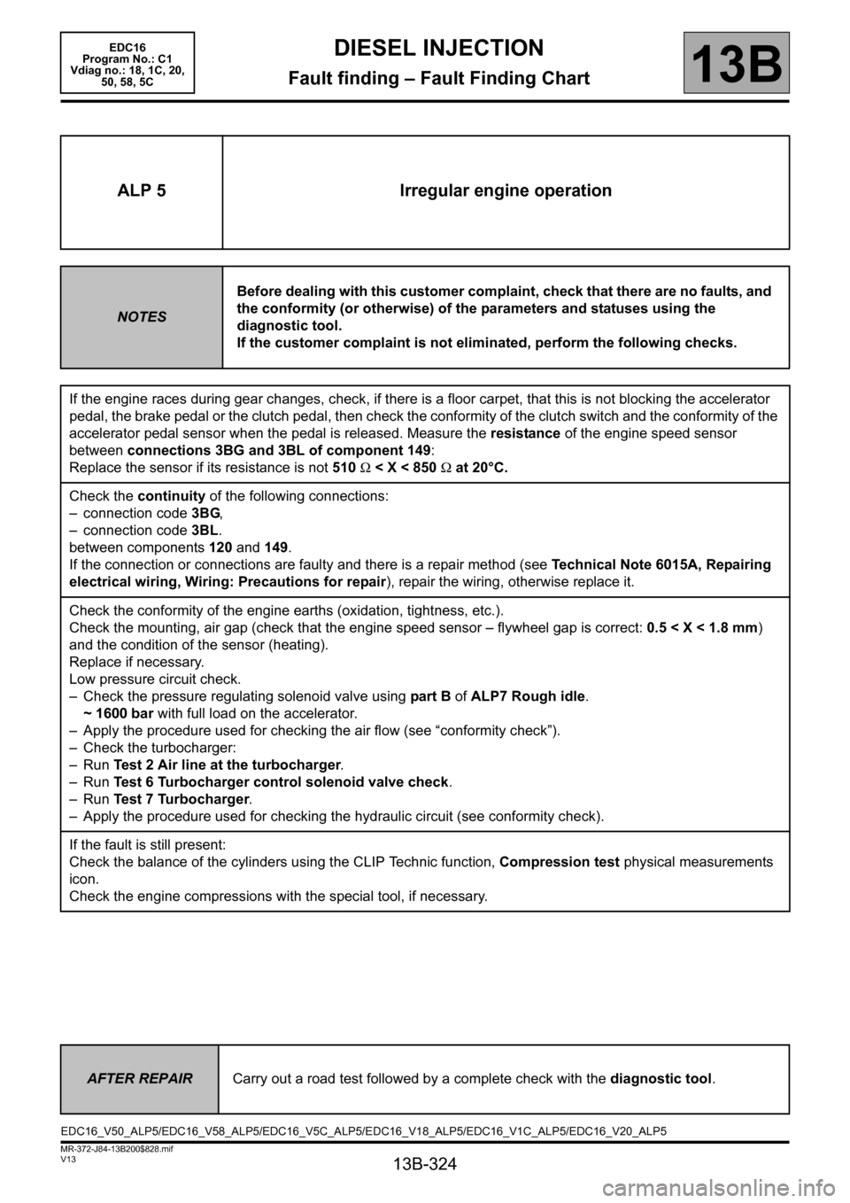
ALP 5 Irregular engine operation
NOTESBefore dealing with this customer complaint, check that there are no faults, and
the conformity (or otherwise) of the parameters and statuses using the
diagnostic tool.
If the customer complaint is not eliminated, perform the following checks.
If the engine races during gear changes, check, if there is a floor carpet, that this is not blocking the accelerator
pedal, the brake pedal or the clutch pedal, then check the conformity of the clutch switch and the conformity of the
accelerator pedal sensor when the pedal is released. Measure the resistance of the engine speed sensor
between connections 3BG and 3BL of component 149:
Replace the sensor if its resistance is not 510 Ω < X < 850 Ω at 20°C.
Check the continuity of the following connections:
– connection code 3BG,
– connection code 3BL.
between components 120 and 149.
If the connection or connections are faulty and there is a repair method (see Technical Note 6015A, Repairing
electrical wiring, Wiring: Precautions for repair), repair the wiring, otherwise replace it.
Check the conformity of the engine earths (oxidation, tightness, etc.).
Check the mounting, air gap (check that the engine speed sensor – flywheel gap is correct: 0.5 < X < 1.8 mm)
and the condition of the sensor (heating).
Replace if necessary.
Low pressure circuit check.
– Check the pressure regulating solenoid valve using part B of ALP7 Rough idle.
~ 1600 bar with full load on the accelerator.
– Apply the procedure used for checking the air flow (see “conformity check”).
– Check the turbocharger:
–Run Test 2 Air line at the turbocharger.
–Run Test 6 Turbocharger control solenoid valve check.
–Run Test 7 Turbocharger.
– Apply the procedure used for checking the hydraulic circuit (see conformity check).
If the fault is still present:
Check the balance of the cylinders using the CLIP Technic function, Compression test physical measurements
icon.
Check the engine compressions with the special tool, if necessary.
AFTER REPAIRCarry out a road test followed by a complete check with the diagnostic tool.
EDC16_V50_ALP5/EDC16_V58_ALP5/EDC16_V5C_ALP5/EDC16_V18_ALP5/EDC16_V1C_ALP5/EDC16_V20_ALP5
Page 325 of 365

13B-325
MR-372-J84-13B200$828.mif
V13
EDC16
Program No.: C1
Vdiag no.: 18, 1C, 20,
50, 58, 5CDIESEL INJECTION
Fault finding – Fault Finding Chart13B
ALP 6 Fuel system leaks
NOTESBefore dealing with this customer complaint, check that there are no faults, and
the conformity (or otherwise) of the parameters and statuses using the
diagnostic tool.
If the customer complaint is not eliminated, perform the following checks.
IMPORTANT
Please observe the cleanliness guidelines and safety advice.
Procedure for checking for an external leak on the fuel circuit:
Clean away traces of grease with clean thinner and wipe the part or parts concerned with cleaning cloths.
Start the engine and increase the engine coolant temperature to 80°C.
Stop the engine and check for traces of grease on the part or parts concerned.
If this is the case, replace the part or parts concerned.
Bleed the fuel circuit and continue the checks.
Does the priming bulb show traces of grease? (Visual
and tactile inspections)
(If there is a priming bulb)
NO
Does the diesel filter show traces of grease?
(Visual and tactile inspections)
NO
Do the fuel return pipes show traces of grease?
(Visual and tactile inspections)
NO
YESCheck the assembly
of the components
and the condition of
the seal at the union
of the two
components, if the
leak is at the seal.
Replace the part or
the parts concerned.
Bleed the fuel circuit
and continue the
checks.
YES
YES
AFTER REPAIRCarry out a road test followed by a complete check with the diagnostic tool.
EDC16_V50_ALP6/EDC16_V58_ALP6/EDC16_V5C_ALP6/EDC16_V18_ALP6/EDC16_V1C_ALP6/EDC16_V20_ALP6
Page 327 of 365

13B-327
MR-372-J84-13B200$828.mif
V13
DIESEL INJECTION
Fault finding – Fault Finding Chart
EDC16
Program No.: C1
Vdiag no.: 18, 1C, 20,
50, 58, 5C
13B
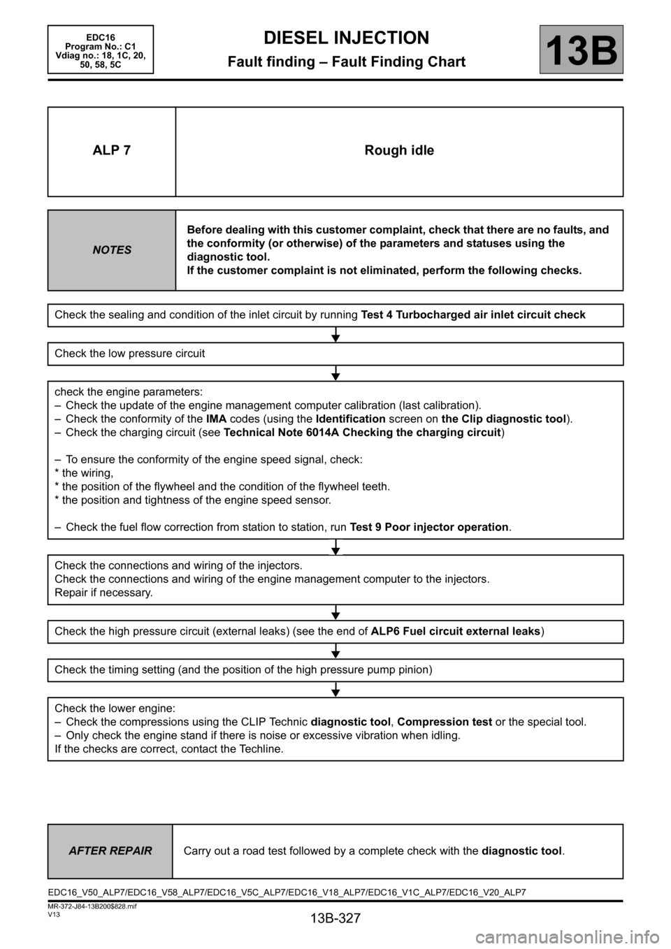
ALP 7 Rough idle
NOTESBefore dealing with this customer complaint, check that there are no faults, and
the conformity (or otherwise) of the parameters and statuses using the
diagnostic tool.
If the customer complaint is not eliminated, perform the following checks.
Check the sealing and condition of the inlet circuit by running Test 4 Turbocharged air inlet circuit check
Check the low pressure circuit
check the engine parameters:
– Check the update of the engine management computer calibration (last calibration).
– Check the conformity of the IMA codes (using the Identification screen on the Clip diagnostic tool).
– Check the charging circuit (see Technical Note 6014A Checking the charging circuit)
– To ensure the conformity of the engine speed signal, check:
* the wiring,
* the position of the flywheel and the condition of the flywheel teeth.
* the position and tightness of the engine speed sensor.
– Check the fuel flow correction from station to station, run Test 9 Poor injector operation.
Check the connections and wiring of the injectors.
Check the connections and wiring of the engine management computer to the injectors.
Repair if necessary.
Check the high pressure circuit (external leaks) (see the end of ALP6 Fuel circuit external leaks)
Check the timing setting (and the position of the high pressure pump pinion)
Check the lower engine:
– Check the compressions using the CLIP Technic diagnostic tool, Compression test or the special tool.
– Only check the engine stand if there is noise or excessive vibration when idling.
If the checks are correct, contact the Techline.
AFTER REPAIRCarry out a road test followed by a complete check with the diagnostic tool.
EDC16_V50_ALP7/EDC16_V58_ALP7/EDC16_V5C_ALP7/EDC16_V18_ALP7/EDC16_V1C_ALP7/EDC16_V20_ALP7
Page 328 of 365

13B-328
MR-372-J84-13B200$828.mif
V13
EDC16
Program No.: C1
Vdiag no.: 18, 1C, 20,
50, 58, 5CDIESEL INJECTION
Fault finding – Fault Finding Chart13B
ALP 8 Oil leaks from the turbocharger
NOTESBefore dealing with this customer complaint, check that there are no faults, and
the conformity (or otherwise) of the parameters and statuses using the
diagnostic tool.
If the customer complaint is not eliminated, perform the following checks.
Check the area around the turbocharger
Note:
An oil leak does not correspond always to a turbocharger fault, the oil leak can arise from the area around the
turbocharger.
According to the vehicle type, maximum visual access will either be from above or from below.
1- Do not start the engine.
Check the area around the turbocharger and identify the origin of the leaks.
Clean the oil traces on the turbocharger.
2- start the engine and let it warm up for several minutes.
IMPORTANT
If the air filter was removed previously, refit it before starting the engine (risks foreign matter entering the air inlet
circuit).
Accelerate with no load several times, progressively increasing the duration before releasing the accelerator
pedal.
Visually inspect the exterior condition of the fuel supply pipes and the turbocharger oil return and the area around
it.
Identify the origin of the leaks.
Is an oil leak present at the air compressor inlet or outlet?
YES NO
Check the air compressor inlet or outlet
Check for a loose interface (inlet or outlet) that is the cause of
the air leak.
Note:
it is normal to find traces of oil inside the pipes at the
turbocharger inlet or outlet as the air passing into the
compressor is laden with oil from the engine rebreathing circuit.
Is the suspected interface properly tightened?
YES
Replace the pipe concerned (see MR 364 (Mégane II), 370 (Scénic II) or 395 (Laguna II), Mechanical, 12B,
Turbocharging).
NOTighten the interface or the
concerned pipe.
End of procedure.
AFTER REPAIRCarry out a road test followed by a complete check with the diagnostic tool.
EDC16_V50_ALP8/EDC16_V58_ALP8/EDC16_V5C_ALP8/EDC16_V18_ALP8/EDC16_V1C_ALP8/EDC16_V20_ALP8
Page 335 of 365

13B-335
MR-372-J84-13B200$828.mif
V13
DIESEL INJECTION
Fault finding – Fault Finding Chart
EDC16
Program No.: C1
Vdiag no.: 18, 1C, 20,
50, 58, 5C
13B
Analysis of output for ALP9 Particle filter warning light comes on too frequently
ALP 9
CONTINUED 4
Output
no. Output conditionCause – type of
drivingRegeneratio
n frequencyWhat to tell the
customer?
Output 1The last 10 regeneration
attempts have failed due to
the engine cutting out.Regeneration failures
caused by engine cut-
off.No
regeneration
frequency
analysis.Explain to the customer
the need to wait until the
end of regeneration
(warning light goes out)
before switching off the
engine.
Output 2The last 10 regeneration
attempts have failed but not
because of the engine cutting
out.Inappropriate driving
profile…No
regeneration
frequency
analysis.Explain again to the
customer the driving
criteria for when the
warning light comes on.
Output 3After successful
regenerations stored in the
memory, the warning light did
not come on. The interval
cannot be calculated.Since the last
successful regeneration
recordings, the driving
profile has been such
that the warning lights
have not come on.Should be
normalVehicle correct
Output 4The interval between a
successful regeneration and
the particle filter warning light
coming on is correct (above
the lowest possible values).
The system does not have
any irregular components.Unfavourable driving
(urban zone,
underspeed etc.)Normal Vehicle correct
AFTER REPAIRCarry out a road test followed by a complete check with the diagnostic tool.
Page 341 of 365

13B-341
MR-372-J84-13B200$900.mif
V13
EDC16
Program No.: C1
Vdiag no.: 18, 1C, 20,
50, 58, 5CDIESEL INJECTION
Fault finding – Tests13B
TEST 2 Turbocharger air chain
Check for the air filter
Check the replacement frequency for the air filter in the Maintenance Booklet.
Compare the part numbers of the air filter fitted to the vehicle and that of the air filter recommended by the
manufacturer.
Check the air filter direction of fitting.
Is the air filter fitted to the vehicle correct?
YES NO
Check the condition of the air filter
Visually inspect the condition of the filter section of
the air filter.
Is either the air filter or its seal damaged?
Is the air filter clogged (does it contain a lot of
impurities)?
NO
Low pressure circuit check
Note:
According to the vehicle type, maximum visual
access will either be from above or from below.
Visually inspect the condition of the following
components:
– fresh air inlet scoop on the front end panel of the
vehicle,
– air filter air inlet pipe,
– filter air pipe up to the compressor inlet,
– air flowmeter mountings.
Is one of these components incorrect
(disconnected, cut, bent, pierced or kinked
pipes)?
NO
YESReplace the air filter (see MR 364
(Mégane II), 370 (Scénic II) or 395
(Laguna II), Mechanical, 12A, Fuel
mixture, Air filter, Removal –
Refitting).
YESReplace the defective parts (see MR 364
(Mégane II), 370 (Scénic II) or 395
(Laguna II), Mechanical, 12B,
Turbocharging).
EDC16_V50_TEST2/EDC16_V58_TEST2/EDC16_V5C_TEST2/EDC16_V18_TEST2/EDC16_V1C_TEST2/EDC16_V20_TEST2
Page 342 of 365

13B-342
MR-372-J84-13B200$900.mif
V13
EDC16
Program No.: C1
Vdiag no.: 18, 1C, 20,
50, 58, 5CDIESEL INJECTION
Fault finding – Tests13B
TEST 2
CONTINUED 1
High pressure circuit check
Note:
According to the vehicle type, maximum visual
access will either be from above or from below.
Visually inspect the condition of the following
components:
– outlet pipe of the compressor to the turbocharging
air cooler,
– turbocharging air cooler outlet pipe at inlet
manifold,
– inlet manifold,
– temperature and pressure sensors.
Is one of these components incorrect
(disconnected, cut, bent, pierced or kinked
pipes)?
NO
Exhaust system check
Visually inspect the condition of the following engine
parts:
– the exhaust manifold circuit to the turbocharger
turbine,
– the turbine outlet pipe to the end of the exhaust
pipe,
– the inlet manifold to the EGR valve
– check that the temperature and pressure sensors
are connected.
Do some of these components have black or
white marks on them?
NO
Run test 6 Turbocharger control solenoid valve check.
YES
Replace the defective parts (see
MR 364 (Mégane II), 370 (Scénic
II) or 395 (Laguna II), Mechanical,
12B, Turbocharging).
YES
Page 343 of 365

13B-343
MR-372-J84-13B200$900.mif
V13
EDC16
Program No.: C1
Vdiag no.: 18, 1C, 20,
50, 58, 5CDIESEL INJECTION
Fault finding – Tests13B
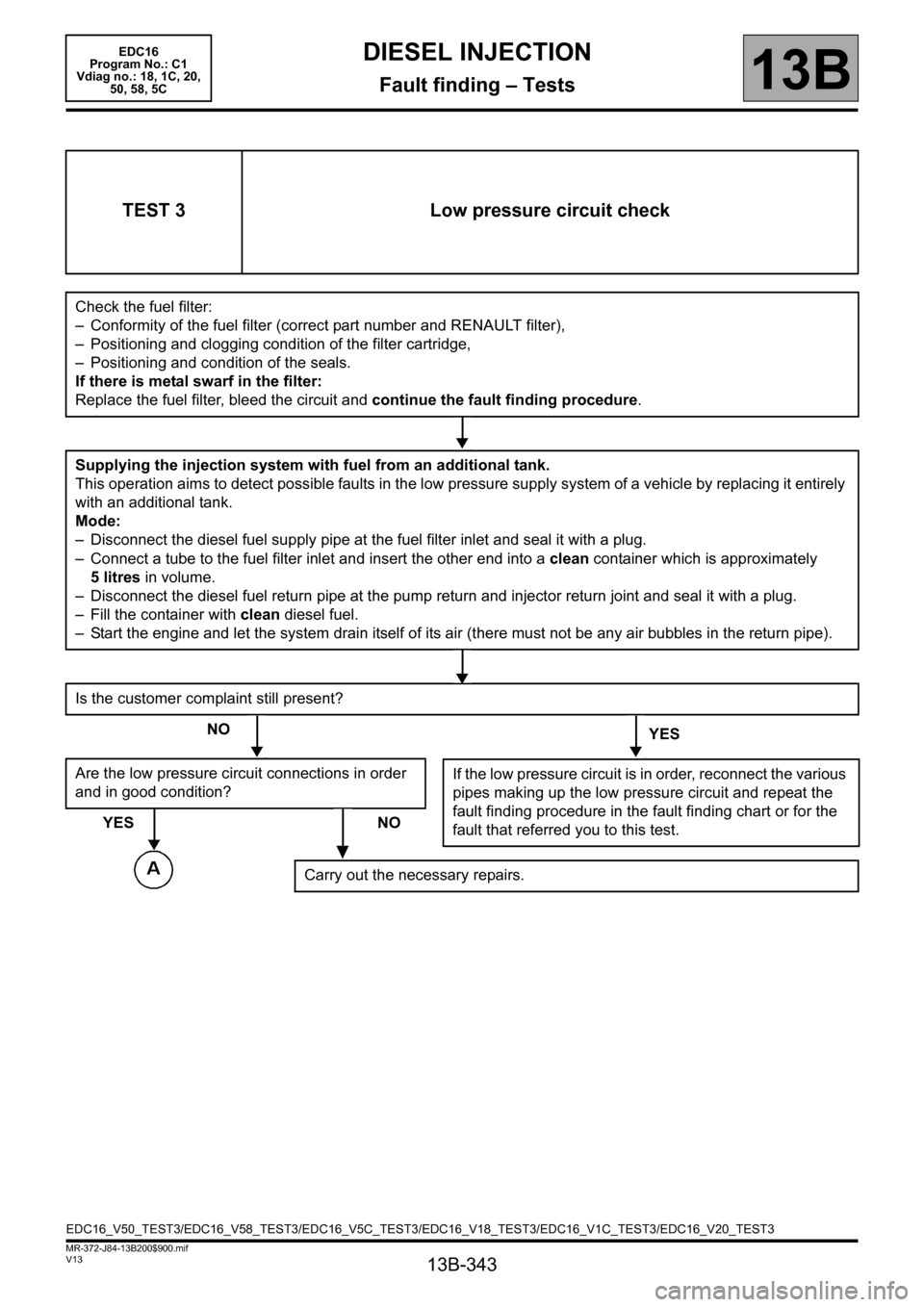
TEST 3 Low pressure circuit check
Check the fuel filter:
– Conformity of the fuel filter (correct part number and RENAULT filter),
– Positioning and clogging condition of the filter cartridge,
– Positioning and condition of the seals.
If there is metal swarf in the filter:
Replace the fuel filter, bleed the circuit and continue the fault finding procedure.
Supplying the injection system with fuel from an additional tank.
This operation aims to detect possible faults in the low pressure supply system of a vehicle by replacing it entirely
with an additional tank.
Mode:
– Disconnect the diesel fuel supply pipe at the fuel filter inlet and seal it with a plug.
– Connect a tube to the fuel filter inlet and insert the other end into a clean container which is approximately
5 litres in volume.
– Disconnect the diesel fuel return pipe at the pump return and injector return joint and seal it with a plug.
– Fill the container with clean diesel fuel.
– Start the engine and let the system drain itself of its air (there must not be any air bubbles in the return pipe).
Is the customer complaint still present?
NO
YES
Are the low pressure circuit connections in order
and in good condition?
YES NO
If the low pressure circuit is in order, reconnect the various
pipes making up the low pressure circuit and repeat the
fault finding procedure in the fault finding chart or for the
fault that referred you to this test.
Carry out the necessary repairs.
EDC16_V50_TEST3/EDC16_V58_TEST3/EDC16_V5C_TEST3/EDC16_V18_TEST3/EDC16_V1C_TEST3/EDC16_V20_TEST3