Page 258 of 3787

OVERHAULAT-241
< SERVICE INFORMATION >
DE
F
G H
I
J
K L
M A
B
AT
N
O P
7. Seal lip 8. D-ring9. Reverse clutch drum
10. Thrust washer 11. Reverse clutch assembly 12. Drive plate
13. Snap ring 14. Needle bearing15. Front sun gear
16. Needle bearing 17. High clutch hub18. Snap ring
19. Retaining plate 20. Drive plate21. Snap ring
22. Cancel cover 23. Spring retainer assembly 24. High clutch piston
25. Input shaft assembly (high clutch drum) 26. Needle bearing
27. High clutch assembly
28. Bearing race 29. Seal ring30. Driven plate
31. Needle bearing 32. Needle bearing33. Overrun clutch hub
34. End bearing 35. Forward clutch hub 36. Needle bearing
37. Rear planetary carrier 38. Rear sun gear39. Front planetary carrier
40. Low one-way clutch 41. Snap ring42. Needle bearing
43. Needle bearing 44. Rear internal gear 45. Thrust washer
46. Forward one-way clutch 47. Thrust washer48. Thrust washer
49. Forward clutch drum 50. Seal ring51. Seal ring
52. Overrun clutch piston 53. Spring retainer assembly 54. Snap ring
55. Dish plate 56. Driven plate57. Retaining plate
58. Snap ring 59. Dish plate60. Driven plate
61. Retaining plate 62. Snap ring63. Forward clutch assembly and over-
run clutch assembly
64. Drive plate 65. Drive plate66. D-ring
67. Forward clutch piston 68. D-ring69. Seal ring
70. Driven plate 71. Snap ring72. Low & reverse brake assembly
73. Retaining plate 74. Drive plate75. Retaining plate
76. Dish plate 77. Driven plate78. Snap ring
79. Spring retainer assembly 80. Low & reverse brake pis-
ton 81. D-ring
Revision: May 2010
2011 Versa
Page 264 of 3787
OVERHAULAT-247
< SERVICE INFORMATION >
DE
F
G H
I
J
K L
M A
B
AT
N
O P
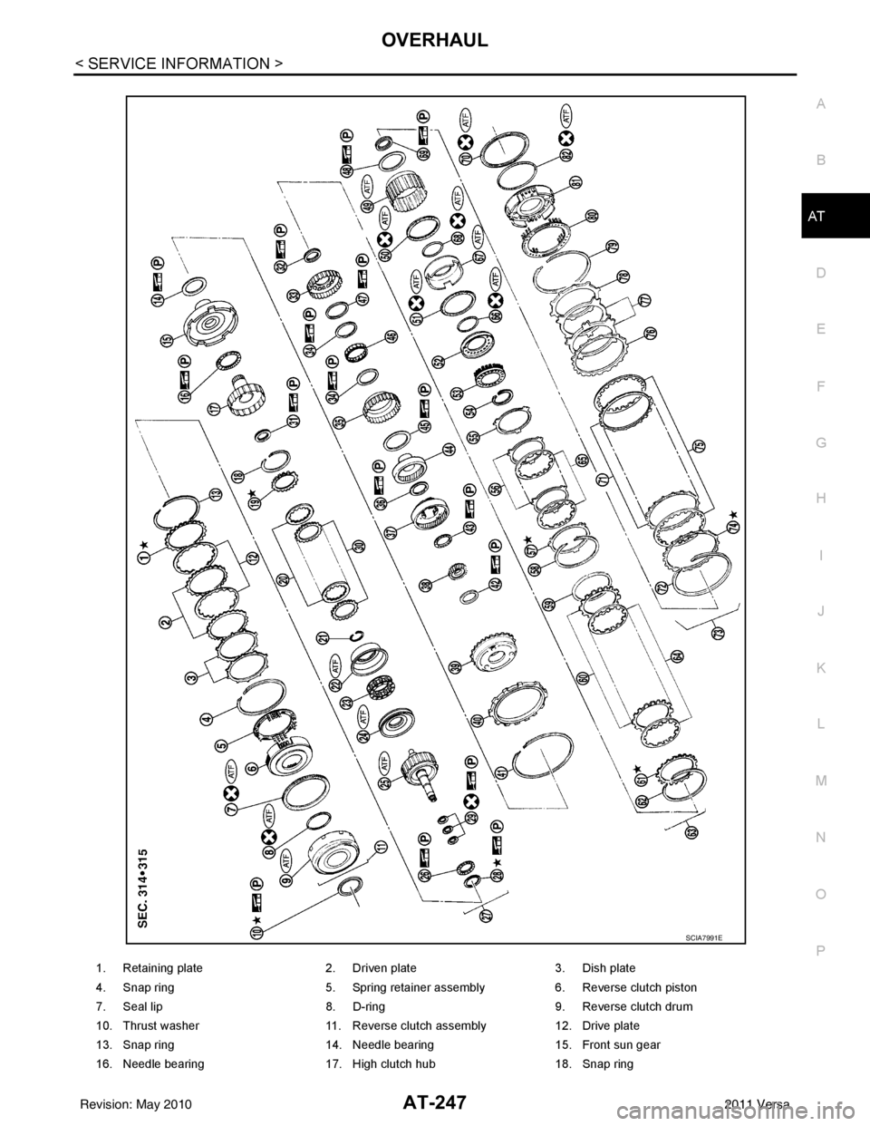
1. Retaining plate 2. Driven plate3. Dish plate
4. Snap ring 5. Spring retainer assembly6. Reverse clutch piston
7. Seal lip 8. D-ring9. Reverse clutch drum
10. Thrust washer 11. Reverse clutch assembly 12. Drive plate
13. Snap ring 14. Needle bearing15. Front sun gear
16. Needle bearing 17. High clutch hub18. Snap ring
SCIA7991E
Revision: May 2010 2011 Versa
Page 265 of 3787

AT-248
< SERVICE INFORMATION >
OVERHAUL
19. Retaining plate20. Drive plate21. Snap ring
22. Cancel cover 23. Spring retainer assembly 24. High clutch piston
25. Input shaft assembly (high clutch drum) 26. Needle bearing
27. High clutch assembly
28. Bearing race 29. Seal ring30. Driven plate
31. Needle bearing 32. Needle bearing33. Overrun clutch hub
34. End bearing 35. Forward clutch hub 36. Needle bearing
37. Rear planetary carrier 38. Rear sun gear 39. Front planetary carrier
40. Low one-way clutch 41. Snap ring42. Needle bearing
43. Needle bearing 44. Rear internal gear 45. Thrust washer
46. Forward one-way clutch 47. Thrust washer48. Thrust washer
49. Forward clutch drum 50. Seal lip51. Seal lip
52. Overrun clutch piston 53. Spring retainer assembly54. Snap ring
55. Dish plate 56. Driven plate57. Retaining plate
58. Snap ring 59. Dish plate60. Driven plate
61. Retaining plate 62. Snap ring63. Forward clutch assembly and over-
run clutch assembly
64. Drive plate 65. Drive plate 66. D-ring
67. Forward clutch piston 68. D-ring 69. Needle bearing
70. Seal lip 71. Driven plate 72. Snap ring
73. Low & reverse brake assembly 74. Retaining plate 75. Drive plate
76. Retaining plate 77. Dish plate78. Driven plate
79. Snap ring 80. Spring retainer assembly 81. Low & reverse brake piston
82. D-ring
Revision: May 2010 2011 Versa
Page 283 of 3787
AT-266
< SERVICE INFORMATION >
DISASSEMBLY
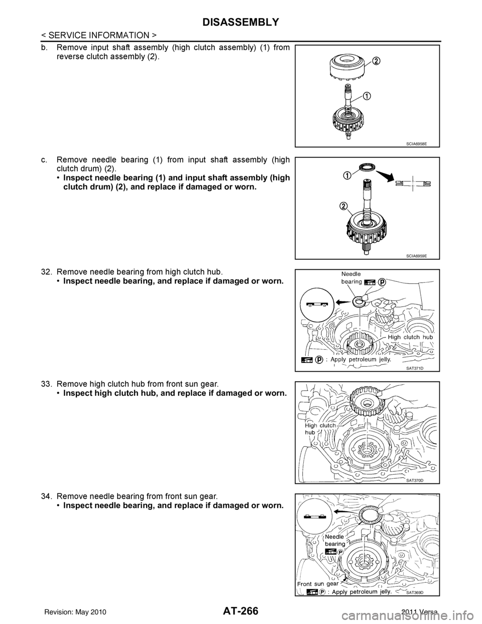
b. Remove input shaft assembly (high clutch assembly) (1) fromreverse clutch assembly (2).
c. Remove needle bearing (1) from input shaft assembly (high clutch drum) (2).
•Inspect needle bearing (1) and input shaft assembly (high
clutch drum) (2), and re place if damaged or worn.
32. Remove needle bearing from high clutch hub. •Inspect needle bearing, and replace if damaged or worn.
33. Remove high clutch hub from front sun gear. •Inspect high clutch hub, and replace if damaged or worn.
34. Remove needle bearing from front sun gear. •Inspect needle bearing, and replace if damaged or worn.
SCIA6958E
SCIA6959E
SAT371D
SAT370D
SAT369D
Revision: May 2010 2011 Versa
Page 335 of 3787
AT-318
< SERVICE INFORMATION >
REPAIR FOR COMPONENT PARTS
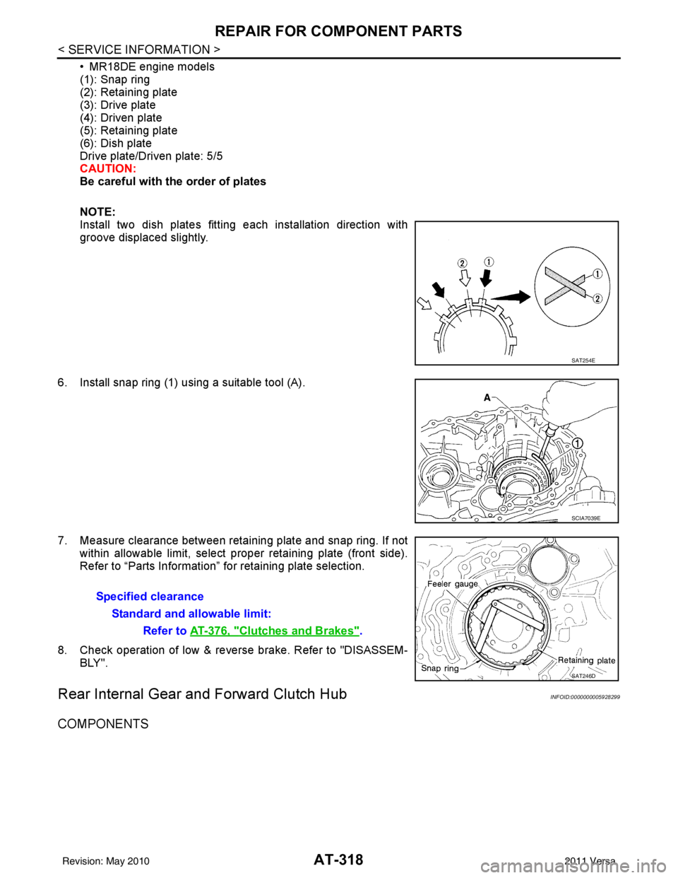
• MR18DE engine models
(1): Snap ring
(2): Retaining plate
(3): Drive plate
(4): Driven plate
(5): Retaining plate
(6): Dish plate
Drive plate/Driven plate: 5/5
CAUTION:
Be careful with the order of plates
NOTE:
Install two dish plates fitting each installation direction with
groove displaced slightly.
6. Install snap ring (1) using a suitable tool (A).
7. Measure clearance between retaining plate and snap ring. If not within allowable limit, select proper retaining plate (front side).
Refer to “Parts Information” for retaining plate selection.
8. Check operation of low & revers e brake. Refer to "DISASSEM-
BLY".
Rear Internal Gear and Forward Clutch HubINFOID:0000000005928299
COMPONENTS
SAT254E
SCIA7039E
Specified clearance
Standard and allowable limit: Refer to AT-376, "
Clutches and Brakes".
SAT246D
Revision: May 2010 2011 Versa
Page 376 of 3787
ASSEMBLYAT-359
< SERVICE INFORMATION >
DE
F
G H
I
J
K L
M A
B
AT
N
O P
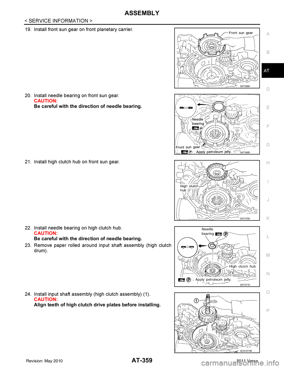
19. Install front sun gear on front planetary carrier.
20. Install needle bearing on front sun gear. CAUTION:
Be careful with the dir ection of needle bearing.
21. Install high clutch hub on front sun gear.
22. Install needle bearing on high clutch hub. CAUTION:
Be careful with the dir ection of needle bearing.
23. Remove paper rolled around input shaft assembly (high clutch drum).
24. Install input shaft assembly (high clutch assembly) (1). CAUTION:
Align teeth of high clutch dr ive plates before installing.
SAT368D
SAT369D
SAT370D
SAT371D
SCIA7079E
Revision: May 2010 2011 Versa
Page 377 of 3787
AT-360
< SERVICE INFORMATION >
ASSEMBLY
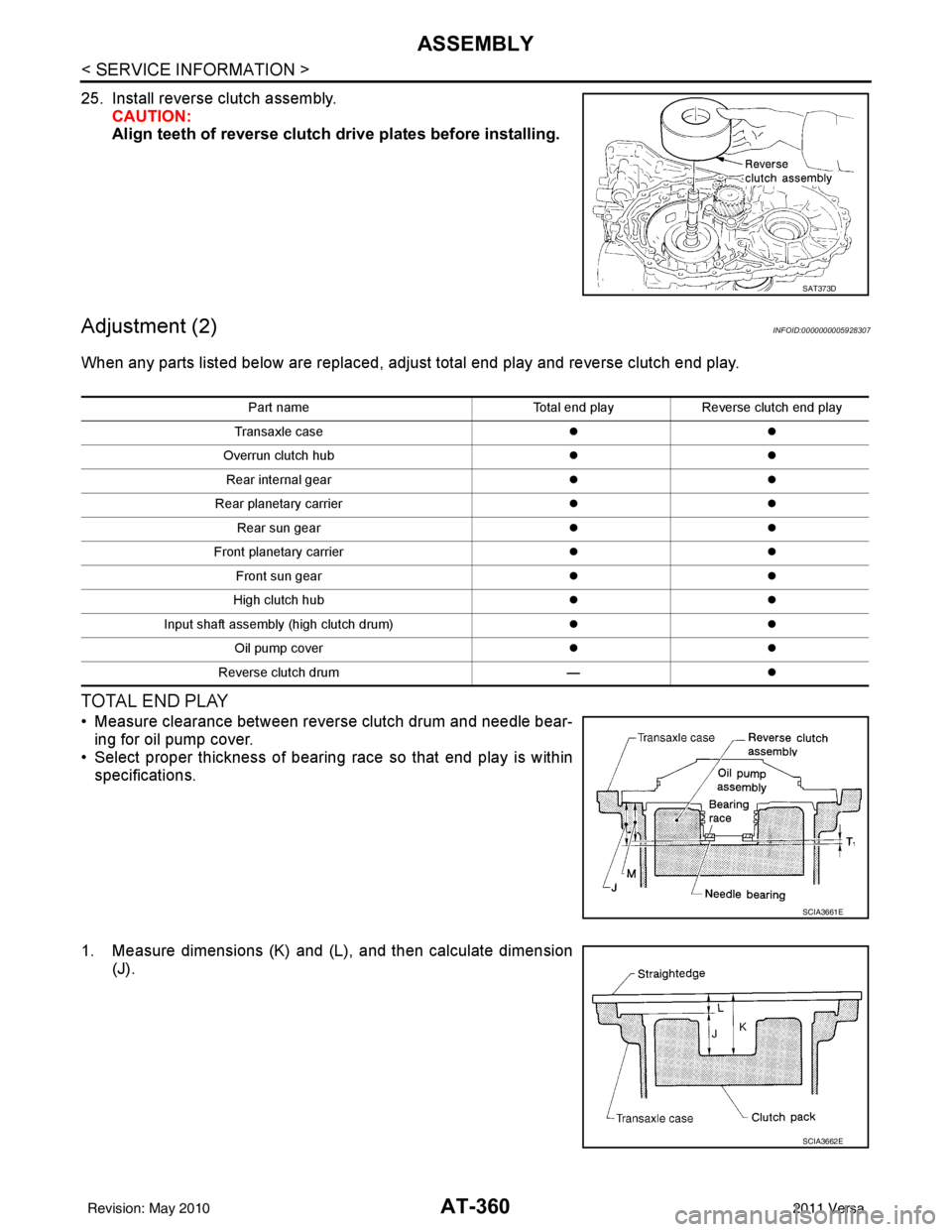
25. Install reverse clutch assembly.CAUTION:
Align teeth of reverse clutch dr ive plates before installing.
Adjustment (2)INFOID:0000000005928307
When any parts listed below are replaced, adjust total end play and reverse clutch end play.
TOTAL END PLAY
• Measure clearance between reverse clutch drum and needle bear-
ing for oil pump cover.
• Select proper thickness of bearing race so that end play is within specifications.
1. Measure dimensions (K) and (L ), and then calculate dimension
(J).
SAT373D
Part name Total end playReverse clutch end play
Transaxle case zz
Overrun clutch hub zz
Rear internal gear zz
Rear planetary carrier zz
Rear sun gear zz
Front planetary carrier zz
Front sun gear zz
High clutch hub zz
Input shaft assembly (high clutch drum) zz
Oil pump cover zz
Reverse clutch drum —z
SCIA3661E
SCIA3662E
Revision: May 2010 2011 Versa
Page 877 of 3787
BR-30
< SERVICE INFORMATION >
FRONT DISC BRAKE
Removal and Installation of Brake Caliper Assembly
INFOID:0000000005928413
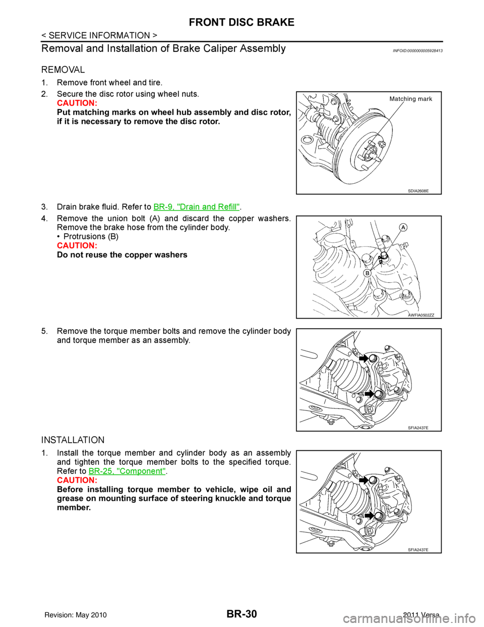
REMOVAL
1. Remove front wheel and tire.
2. Secure the disc rotor using wheel nuts.
CAUTION:
Put matching marks on wheel hub assembly and disc rotor,
if it is necessary to remove the disc rotor.
3. Drain brake fluid. Refer to BR-9, "
Drain and Refill".
4. Remove the union bolt (A) and discard the copper washers. Remove the brake hose from the cylinder body.
• Protrusions (B)
CAUTION:
Do not reuse the copper washers
5. Remove the torque member bolts and remove the cylinder body and torque member as an assembly.
INSTALLATION
1. Install the torque member and cylinder body as an assemblyand tighten the torque member bolts to the specified torque.
Refer to BR-25, "
Component".
CAUTION:
Before installing torque member to vehicle, wipe oil and
grease on mounting surface of steering knuckle and torque
member.
SDIA2608E
AWFIA0502ZZ
SFIA2437E
SFIA2437E
Revision: May 2010 2011 Versa