2011 NISSAN TIIDA Engine warning
[x] Cancel search: Engine warningPage 13 of 3787

ACC-2
< SERVICE INFORMATION >
PRECAUTIONS
SERVICE INFORMATION
PRECAUTIONS
Precaution for Supplemental Restraint System (SRS) "AIR BAG" and "SEAT BELT
PRE-TENSIONER"
INFOID:0000000006405207
The Supplemental Restraint System such as “A IR BAG” and “SEAT BELT PRE-TENSIONER”, used along
with a front seat belt, helps to reduce the risk or severity of injury to the driver and front passenger for certain
types of collision. This system includes seat belt switch inputs and dual stage front air bag modules. The SRS
system uses the seat belt switches to determine the front air bag deployment, and may only deploy one front
air bag, depending on the severity of a collision and w hether the front occupants are belted or unbelted.
Information necessary to service the system safely is included in the SRS and SB section of this Service Man-
ual.
WARNING:
• To avoid rendering the SRS inopera tive, which could increase the risk of personal injury or death in
the event of a collision which would result in air bag inflation, all maintenance must be performed by
an authorized NISSAN/INFINITI dealer.
• Improper maintenance, including incorrect removal and installation of the SRS can lead to personal
injury caused by unintent ional activation of the system. For re moval of Spiral Cable and Air Bag
Module, see the SRS section.
• Do not use electrical test equipmen t on any circuit related to the SRS unless instructed to in this
Service Manual. SRS wiring harn esses can be identified by yellow and/or orange harnesses or har-
ness connectors.
PRECAUTIONS WHEN USING POWER TOOLS (AIR OR ELECTRIC) AND HAMMERS
WARNING:
• When working near the Airbag Diagnosis Sensor Unit or other Airbag System sensors with the Igni-
tion ON or engine running, DO NOT use air or electri c power tools or strike near the sensor(s) with a
hammer. Heavy vibration could activate the sensor( s) and deploy the air bag(s), possibly causing
serious injury.
• When using air or electric power tools or hammers , always switch the Ignition OFF, disconnect the
battery, and wait at least 3 minu tes before performing any service.
Precaution Necessary for Steering W heel Rotation After Battery Disconnect
INFOID:0000000005928708
NOTE:
• This Procedure is applied only to models with Intelligent Key system and NATS (NISSAN ANTI-THEFT SYS-
TEM).
• Remove and install all control units after disconnecting both battery cables with the ignition knob in the
″LOCK ″ position.
• Always use CONSULT-III to perform self-diagnosis as a part of each function inspection after finishing work.
If DTC is detected, perform trouble diagnosis according to self-diagnostic results.
For models equipped with the Intelligent Key system and NATS, an electrically controlled steering lock mech-
anism is adopted on the key cylinder.
For this reason, if the battery is disconnected or if the battery is discharged, the steering wheel will lock and
steering wheel rotation will become impossible.
If steering wheel rotation is required when battery pow er is interrupted, follow the procedure below before
starting the repair operation.
OPERATION PROCEDURE
1. Connect both battery cables. NOTE:
Supply power using jumper cables if battery is discharged.
2. Use the Intelligent Key or mechanical key to turn the ignition switch to the ″ACC ″ position. At this time, the
steering lock will be released.
3. Disconnect both battery cables. The steering lock will remain released and the steering wheel can be rotated.
4. Perform the necessary repair operation.
Revision: May 2010 2011 Versa
Page 17 of 3787

ACS-2
< SERVICE INFORMATION >
AUTOMATIC SPEED CONTROL DEVICE (ASCD)
SERVICE INFORMATION
AUTOMATIC SPEED CONTROL DEVICE (ASCD)
Precaution for Supplemental Restraint System (SRS) "AIR BAG" and "SEAT BELT
PRE-TENSIONER"
INFOID:0000000005929265
The Supplemental Restraint System such as “A IR BAG” and “SEAT BELT PRE-TENSIONER”, used along
with a front seat belt, helps to reduce the risk or severity of injury to the driver and front passenger for certain
types of collision. This system includes seat belt switch inputs and dual stage front air bag modules. The SRS
system uses the seat belt switches to determine the front air bag deployment, and may only deploy one front
air bag, depending on the severity of a collision and w hether the front occupants are belted or unbelted.
Information necessary to service the system safely is included in the SRS and SB section of this Service Man-
ual.
WARNING:
• To avoid rendering the SRS inopera tive, which could increase the risk of personal injury or death in
the event of a collision which would result in air bag inflation, all maintenance must be performed by
an authorized NISSAN/INFINITI dealer.
• Improper maintenance, including incorrect removal and installation of the SRS can lead to personal
injury caused by unintent ional activation of the system. For re moval of Spiral Cable and Air Bag
Module, see the SRS section.
• Do not use electrical test equipmen t on any circuit related to the SRS unless instructed to in this
Service Manual. SRS wiring harn esses can be identified by yellow and/or orange harnesses or har-
ness connectors.
PRECAUTIONS WHEN USING POWER TOOLS (AIR OR ELECTRIC) AND HAMMERS
WARNING:
• When working near the Airbag Diagnosis Sensor Unit or other Airbag System sensors with the Igni-
tion ON or engine running, DO NOT use air or electri c power tools or strike near the sensor(s) with a
hammer. Heavy vibration could activate the sensor( s) and deploy the air bag(s), possibly causing
serious injury.
• When using air or electric power tools or hammers , always switch the Ignition OFF, disconnect the
battery, and wait at least 3 minu tes before performing any service.
DescriptionINFOID:0000000005929266
Regarding the information for ASCD system, refer to EC-523, "System Description".
Revision: May 2010 2011 Versa
Page 24 of 3787

PRECAUTIONSAT-7
< SERVICE INFORMATION >
DE
F
G H
I
J
K L
M A
B
AT
N
O P
PRECAUTIONS
Precaution for Supplemental Restraint System (SRS) "AIR BAG" and "SEAT BELT
PRE-TENSIONER"
INFOID:0000000006413332
The Supplemental Restraint System such as “AIR BAG” and “SEAT BELT PRE-TENSIONER”, used along
with a front seat belt, helps to reduce the risk or severi ty of injury to the driver and front passenger for certain
types of collision. This system includes seat belt switch inputs and dual stage front air bag modules. The SRS
system uses the seat belt switches to determine the front air bag deployment, and may only deploy one front
air bag, depending on the severity of a collision and w hether the front occupants are belted or unbelted.
Information necessary to service the system safely is included in the SRS and SB section of this Service Man-
ual.
WARNING:
• To avoid rendering the SRS inoper ative, which could increase the risk of personal injury or death in
the event of a collision which would result in air bag inflation, all maintenance must be performed by
an authorized NISSAN/INFINITI dealer.
• Improper maintenance, including in correct removal and installation of the SRS can lead to personal
injury caused by unintentional act ivation of the system. For removal of Spiral Cable and Air Bag
Module, see the SRS section.
• Do not use electrical test equipm ent on any circuit related to the SRS unless instructed to in this
Service Manual. SRS wiring harnesses can be identi fied by yellow and/or orange harnesses or har-
ness connectors.
PRECAUTIONS WHEN USING POWER TOOLS (AIR OR ELECTRIC) AND HAMMERS
WARNING:
• When working near the Airbag Diagnosis Sensor Un it or other Airbag System sensors with the Igni-
tion ON or engine running, DO NOT use air or el ectric power tools or strike near the sensor(s) with a
hammer. Heavy vibration could activate the sensor( s) and deploy the air bag(s), possibly causing
serious injury.
• When using air or electric power tools or hammers, always switch the Ignition OFF, disconnect the battery, and wait at least 3 minutes before performing any service.
Precaution Necessary for Steering Wheel Rotation After Battery Disconnect
INFOID:0000000005928064
NOTE:
• This Procedure is applied only to models with Intelligent Key system and NVIS /IVIS (NISSAN/INFINITI
VEHICLE IMMOBILIZER SYSTEM - NATS).
• Remove and install all control units after disconnecti ng both battery cables with the ignition knob in the
″ LOCK ″ position.
• Always use CONSULT-III to perform self-diagnosis as a part of each function inspection after finishing work.
If DTC is detected, perform trouble diagnosis according to self-diagnostic results.
For models equipped with the Intelligent Key system and NVIS/IVIS, an electrically controlled steering lock
mechanism is adopted on the key cylinder.
For this reason, if the battery is disconnected or if the battery is discharged, the steering wheel will lock and
steering wheel rotation will become impossible.
If steering wheel rotation is required when battery power is interrupted, follow the procedure below before
starting the repair operation.
OPERATION PROCEDURE
1. Connect both battery cables. NOTE:
Supply power using jumper cables if battery is discharged.
2. Use the Intelligent Key or mechanical key to turn the ignition switch to the ″ACC ″ position. At this time, the
steering lock will be released.
3. Disconnect both battery cables. The steering lock will remain released and the steering wheel can be
rotated.
4. Perform the necessary repair operation.
5. When the repair work is completed, return the ignition switch to the ″LOCK ″ position before connecting
the battery cables. (At this time, the steering lock mechanism will engage.)
Revision: May 2010 2011 Versa
Page 400 of 3787
![NISSAN TIIDA 2011 Service Repair Manual PRECAUTIONSAV-3
< SERVICE INFORMATION > [AUDIO WITHOUT NAVIGATION]
C
D
E
F
G H
I
J
L
M A
B
AV
N
O P
SERVICE INFORMATION
PRECAUTIONS
Precaution for Supplemental Restraint System (SRS) "AIR BAG" and "S](/manual-img/5/57396/w960_57396-399.png "NISSAN TIIDA 2011 Service Repair Manual PRECAUTIONSAV-3
< SERVICE INFORMATION > [AUDIO WITHOUT NAVIGATION]
C
D
E
F
G H
I
J
L
M A
B
AV
N
O P
SERVICE INFORMATION
PRECAUTIONS
Precaution for Supplemental Restraint System (SRS) \"AIR BAG\" and \"S")
PRECAUTIONSAV-3
< SERVICE INFORMATION > [AUDIO WITHOUT NAVIGATION]
C
D
E
F
G H
I
J
L
M A
B
AV
N
O P
SERVICE INFORMATION
PRECAUTIONS
Precaution for Supplemental Restraint System (SRS) "AIR BAG" and "SEAT BELT
PRE-TENSIONER"
INFOID:0000000006412032
The Supplemental Restraint System such as “AIR BAG” and “SEAT BELT PRE-TENSIONER”, used along
with a front seat belt, helps to reduce the risk or severi ty of injury to the driver and front passenger for certain
types of collision. This system includes seat belt switch inputs and dual stage front air bag modules. The SRS
system uses the seat belt switches to determine the front air bag deployment, and may only deploy one front
air bag, depending on the severity of a collision and w hether the front occupants are belted or unbelted.
Information necessary to service the system safely is included in the SRS and SB section of this Service Man-
ual.
WARNING:
• To avoid rendering the SRS inoper ative, which could increase the risk of personal injury or death in
the event of a collision which would result in air bag inflation, all maintenance must be performed by
an authorized NISSAN/INFINITI dealer.
• Improper maintenance, including in correct removal and installation of the SRS can lead to personal
injury caused by unintentional act ivation of the system. For removal of Spiral Cable and Air Bag
Module, see the SRS section.
• Do not use electrical test equipm ent on any circuit related to the SRS unless instructed to in this
Service Manual. SRS wiring harnesses can be identi fied by yellow and/or orange harnesses or har-
ness connectors.
PRECAUTIONS WHEN USING POWER TOOLS (AIR OR ELECTRIC) AND HAMMERS
WARNING:
• When working near the Airbag Diagnosis Sensor Un it or other Airbag System sensors with the Igni-
tion ON or engine running, DO NOT use air or el ectric power tools or strike near the sensor(s) with a
hammer. Heavy vibration could activate the sensor( s) and deploy the air bag(s), possibly causing
serious injury.
• When using air or electric power tools or hammers, always switch the Ignition OFF, disconnect the battery, and wait at least 3 minutes before performing any service.
Precaution Necessary for Steering Wheel Rotation After Battery Disconnect
INFOID:0000000006412033
NOTE:
• This Procedure is applied only to models with Intelligent Key system and NATS (NISSAN ANTI-THEFT SYS-
TEM).
• Remove and install all control units after disconnecti ng both battery cables with the ignition knob in the
″ LOCK ″ position.
• Always use CONSULT-III to perform self-diagnosis as a part of each function inspection after finishing work.
If DTC is detected, perform trouble diagnosis according to self-diagnostic results.
For models equipped with the Intelligent Key system and NATS , an electrically controlled steering lock mech-
anism is adopted on the key cylinder.
For this reason, if the battery is disconnected or if the battery is discharged, the steering wheel will lock and
steering wheel rotation will become impossible.
If steering wheel rotation is required when battery power is interrupted, follow the procedure below before
starting the repair operation.
OPERATION PROCEDURE
1. Connect both battery cables. NOTE:
Supply power using jumper cables if battery is discharged.
2. Use the Intelligent Key or mechanical key to turn the ignition switch to the ″ACC ″ position. At this time, the
steering lock will be released.
3. Disconnect both battery cables. The steering lock will remain released and the steering wheel can be
rotated.
4. Perform the necessary repair operation.
Revision: May 2010 2011 Versa
Page 447 of 3787
![NISSAN TIIDA 2011 Service Repair Manual AV-50
< SERVICE INFORMATION >[AUDIO WITH NAVIGATION]
PRECAUTIONS
SERVICE INFORMATION
PRECAUTIONS
Precaution for Supplemental Restraint Syst
em (SRS) "AIR BAG" and "SEAT BELT
PRE-TENSIONER"
INFOID:000](/manual-img/5/57396/w960_57396-446.png "NISSAN TIIDA 2011 Service Repair Manual AV-50
< SERVICE INFORMATION >[AUDIO WITH NAVIGATION]
PRECAUTIONS
SERVICE INFORMATION
PRECAUTIONS
Precaution for Supplemental Restraint Syst
em (SRS) \"AIR BAG\" and \"SEAT BELT
PRE-TENSIONER\"
INFOID:000")
AV-50
< SERVICE INFORMATION >[AUDIO WITH NAVIGATION]
PRECAUTIONS
SERVICE INFORMATION
PRECAUTIONS
Precaution for Supplemental Restraint Syst
em (SRS) "AIR BAG" and "SEAT BELT
PRE-TENSIONER"
INFOID:0000000006412034
The Supplemental Restraint System such as “A IR BAG” and “SEAT BELT PRE-TENSIONER”, used along
with a front seat belt, helps to reduce the risk or severity of injury to the driver and front passenger for certain
types of collision. This system includes seat belt switch inputs and dual stage front air bag modules. The SRS
system uses the seat belt switches to determine the front air bag deployment, and may only deploy one front
air bag, depending on the severity of a collision and w hether the front occupants are belted or unbelted.
Information necessary to service the system safely is included in the SRS and SB section of this Service Man-
ual.
WARNING:
• To avoid rendering the SRS inopera tive, which could increase the risk of personal injury or death in
the event of a collision which would result in air bag inflation, all maintenance must be performed by
an authorized NISSAN/INFINITI dealer.
• Improper maintenance, including incorrect removal and installation of the SRS can lead to personal
injury caused by unintent ional activation of the system. For re moval of Spiral Cable and Air Bag
Module, see the SRS section.
• Do not use electrical test equipmen t on any circuit related to the SRS unless instructed to in this
Service Manual. SRS wiring harn esses can be identified by yellow and/or orange harnesses or har-
ness connectors.
PRECAUTIONS WHEN USING POWER TOOLS (AIR OR ELECTRIC) AND HAMMERS
WARNING:
• When working near the Airbag Diagnosis Sensor Unit or other Airbag System sensors with the Igni-
tion ON or engine running, DO NOT use air or electri c power tools or strike near the sensor(s) with a
hammer. Heavy vibration could activate the sensor( s) and deploy the air bag(s), possibly causing
serious injury.
• When using air or electric power tools or hammers , always switch the Ignition OFF, disconnect the
battery, and wait at least 3 minu tes before performing any service.
Precaution Necessary for Steering W heel Rotation After Battery Disconnect
INFOID:0000000006412035
NOTE:
• This Procedure is applied only to models with Intelligent Key system and NATS (NISSAN ANTI-THEFT SYS-
TEM).
• Remove and install all control units after disconnecting both battery cables with the ignition knob in the
″LOCK ″ position.
• Always use CONSULT-III to perform self-diagnosis as a part of each function inspection after finishing work.
If DTC is detected, perform trouble diagnosis according to self-diagnostic results.
For models equipped with the Intelligent Key system and NATS, an electrically controlled steering lock mech-
anism is adopted on the key cylinder.
For this reason, if the battery is disconnected or if the battery is discharged, the steering wheel will lock and
steering wheel rotation will become impossible.
If steering wheel rotation is required when battery pow er is interrupted, follow the procedure below before
starting the repair operation.
OPERATION PROCEDURE
1. Connect both battery cables. NOTE:
Supply power using jumper cables if battery is discharged.
2. Use the Intelligent Key or mechanical key to turn the ignition switch to the ″ACC ″ position. At this time, the
steering lock will be released.
3. Disconnect both battery cables. The steering lock will remain released and the steering wheel can be rotated.
4. Perform the necessary repair operation.
Revision: May 2010 2011 Versa
Page 492 of 3787

BCS-2
< SERVICE INFORMATION >
PRECAUTIONS
SERVICE INFORMATION
PRECAUTIONS
Precaution for Supplemental Restraint System (SRS) "AIR BAG" and "SEAT BELT
PRE-TENSIONER"
INFOID:0000000005929254
The Supplemental Restraint System such as “A IR BAG” and “SEAT BELT PRE-TENSIONER”, used along
with a front seat belt, helps to reduce the risk or severity of injury to the driver and front passenger for certain
types of collision. This system includes seat belt switch inputs and dual stage front air bag modules. The SRS
system uses the seat belt switches to determine the front air bag deployment, and may only deploy one front
air bag, depending on the severity of a collision and w hether the front occupants are belted or unbelted.
Information necessary to service the system safely is included in the SRS and SB section of this Service Man-
ual.
WARNING:
• To avoid rendering the SRS inopera tive, which could increase the risk of personal injury or death in
the event of a collision which would result in air bag inflation, all maintenance must be performed by
an authorized NISSAN/INFINITI dealer.
• Improper maintenance, including incorrect removal and installation of the SRS can lead to personal
injury caused by unintent ional activation of the system. For re moval of Spiral Cable and Air Bag
Module, see the SRS section.
• Do not use electrical test equipmen t on any circuit related to the SRS unless instructed to in this
Service Manual. SRS wiring harn esses can be identified by yellow and/or orange harnesses or har-
ness connectors.
PRECAUTIONS WHEN USING POWER TOOLS (AIR OR ELECTRIC) AND HAMMERS
WARNING:
• When working near the Airbag Diagnosis Sensor Unit or other Airbag System sensors with the Igni-
tion ON or engine running, DO NOT use air or electri c power tools or strike near the sensor(s) with a
hammer. Heavy vibration could activate the sensor( s) and deploy the air bag(s), possibly causing
serious injury.
• When using air or electric power tools or hammers , always switch the Ignition OFF, disconnect the
battery, and wait at least 3 minu tes before performing any service.
Precaution Necessary for Steering W heel Rotation After Battery Disconnect
INFOID:0000000006413290
NOTE:
• This Procedure is applied only to models with Intelligent Key system and NATS (NISSAN ANTI-THEFT SYS-
TEM).
• Remove and install all control units after disconnecting both battery cables with the ignition knob in the
″LOCK ″ position.
• Always use CONSULT-III to perform self-diagnosis as a part of each function inspection after finishing work.
If DTC is detected, perform trouble diagnosis according to self-diagnostic results.
For models equipped with the Intelligent Key system and NATS, an electrically controlled steering lock mech-
anism is adopted on the key cylinder.
For this reason, if the battery is disconnected or if the battery is discharged, the steering wheel will lock and
steering wheel rotation will become impossible.
If steering wheel rotation is required when battery pow er is interrupted, follow the procedure below before
starting the repair operation.
OPERATION PROCEDURE
1. Connect both battery cables. NOTE:
Supply power using jumper cables if battery is discharged.
2. Use the Intelligent Key or mechanical key to turn the ignition switch to the ″ACC ″ position. At this time, the
steering lock will be released.
3. Disconnect both battery cables. The steering lock will remain released and the steering wheel can be rotated.
4. Perform the necessary repair operation.
Revision: May 2010 2011 Versa
Page 514 of 3787

BL-4
< SERVICE INFORMATION >
PRECAUTIONS
SERVICE INFORMATION
PRECAUTIONS
Precaution for Supplemental Restraint System (SRS) "AIR BAG" and "SEAT BELT
PRE-TENSIONER"
INFOID:0000000005929267
The Supplemental Restraint System such as “A IR BAG” and “SEAT BELT PRE-TENSIONER”, used along
with a front seat belt, helps to reduce the risk or severity of injury to the driver and front passenger for certain
types of collision. This system includes seat belt switch inputs and dual stage front air bag modules. The SRS
system uses the seat belt switches to determine the front air bag deployment, and may only deploy one front
air bag, depending on the severity of a collision and w hether the front occupants are belted or unbelted.
Information necessary to service the system safely is included in the SRS and SB section of this Service Man-
ual.
WARNING:
• To avoid rendering the SRS inopera tive, which could increase the risk of personal injury or death in
the event of a collision which would result in air bag inflation, all maintenance must be performed by
an authorized NISSAN/INFINITI dealer.
• Improper maintenance, including incorrect removal and installation of the SRS can lead to personal
injury caused by unintent ional activation of the system. For re moval of Spiral Cable and Air Bag
Module, see the SRS section.
• Do not use electrical test equipmen t on any circuit related to the SRS unless instructed to in this
Service Manual. SRS wiring harn esses can be identified by yellow and/or orange harnesses or har-
ness connectors.
PRECAUTIONS WHEN USING POWER TOOLS (AIR OR ELECTRIC) AND HAMMERS
WARNING:
• When working near the Airbag Diagnosis Sensor Unit or other Airbag System sensors with the Igni-
tion ON or engine running, DO NOT use air or electri c power tools or strike near the sensor(s) with a
hammer. Heavy vibration could activate the sensor( s) and deploy the air bag(s), possibly causing
serious injury.
• When using air or electric power tools or hammers , always switch the Ignition OFF, disconnect the
battery, and wait at least 3 minu tes before performing any service.
Precaution Necessary for Steering W heel Rotation After Battery Disconnect
INFOID:0000000005929268
NOTE:
• This procedure is applied only to models with Intell igent Key system and NVIS/IVIS (NISSAN/INFINITI
VEHICLE IMMOBILIZER SYSTEM - NATS).
• Remove and install all control units after disconnec ting both battery cables with the ignition in the ″LOCK ″
position.
• Always use CONSULT-III to perform self-diagnosis as a part of each function inspection after finishing work.
If DTC is detected, perform trouble diagnosis according to self-diagnostic results.
For models equipped with the Intelligent Key system and NVIS /IVIS, an electrically controlled steering lock
mechanism is adopted on the key cylinder.
For this reason, if the battery is disconnected or if the battery is discharged, the steering wheel will lock and
steering wheel rotation will become impossible.
If steering wheel rotation is required when battery pow er is interrupted, follow the procedure below before
starting the repair operation.
OPERATION PROCEDURE
1. Connect both battery cables. NOTE:
Supply power using jumper cables if battery is discharged.
2. Use the Intelligent Key or mechanical key to turn the ignition switch to the ″ACC ″ position. At this time, the
steering lock will be released.
3. Disconnect both battery cables. The steering lock will remain released and the steering wheel can be rotated.
4. Perform the necessary repair operation.
Revision: May 2010 2011 Versa
Page 598 of 3787
BL-88
< SERVICE INFORMATION >
INTELLIGENT KEY SYSTEM
System Description
INFOID:0000000005929328
• The Intelligent Key system is a system that makes it possible to lock and unlock the door locks (door lock/
unlock function), and start the engine (engine start func tion) by carrying around the Intelligent Key (without
some key operation), which operates based on the results of electronic ID verification using two-way com-
munications between the Intelligent Key and the vehicle (Intelligent Key unit).
• Vehicles equipped with a manual transmission include a key interlock solenoid located in the steering col- umn to prevent accidental shut-off of the ignition sw itch and locking of the steering wheel during driving con-
dition when the vehicle is moving.
CAUTION:
The driver should always carry the Intelligent Key
• Operation of the remote controller buttons on the Inte lligent Key also provides the same functions as the
remote control entry system. (Remote keyless entry functions)
• If an action that does not meet the operating conditions of the Intelligent Key system is taken, the buzzer
goes off to inform the driver. (Warning chime functions)
• When a door lock is locked or unlocked with request switch or remote controller button operation, the hazard
lamps flash and the buzzer (outside vehicle) sounds (Hazard and buzzer reminder function).
• Even if the Intelligent Key battery is completely discharged, the door locks can be locked and unlocked and the engine started with the mechanical key built into the Intelligent Key.
• The settings for each function can be changed with the CONSULT-III.
• If an Intelligent Key is lost, a new Intelligent Key can be registered. A maximum of 4 Intelligent Keys can be registered.
• It has been made possible to diagnose the system and r egister an Intelligent Key with the CONSULT-III.
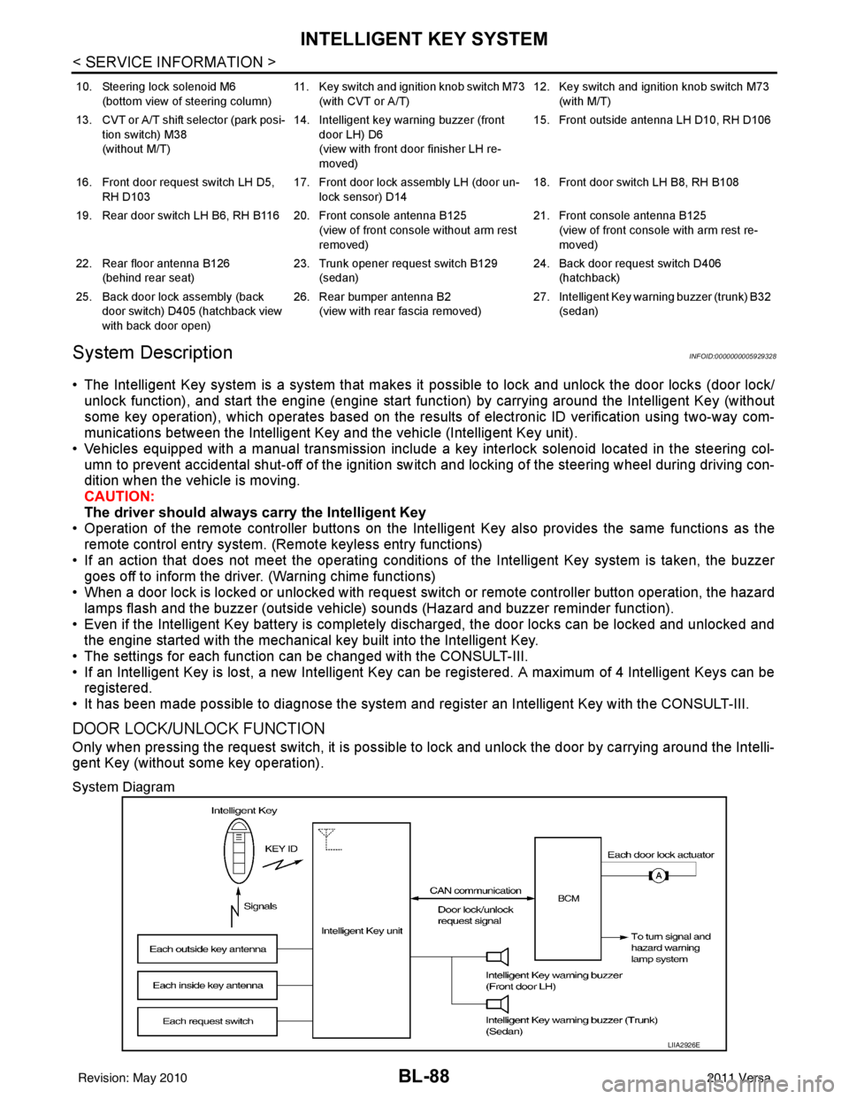
DOOR LOCK/UNLOCK FUNCTION
Only when pressing the request switch, it is possible to lock and unlock the door by carrying around the Intelli-
gent Key (without some key operation).
System Diagram
10. Steering lock solenoid M6
(bottom view of steering column) 11. Key switch and ignition knob switch M73
(with CVT or A/T) 12. Key switch and ignition knob switch M73
(with M/T)
13. CVT or A/T shift selector (park posi- tion switch) M38
(without M/T) 14. Intelligent key warning buzzer (front
door LH) D6
(view with front door finisher LH re-
moved) 15. Front outside antenna LH D10, RH D106
16. Front door request switch LH D5, RH D103 17. Front door lock assembly LH (door un-
lock sensor) D14 18. Front door switch LH B8, RH B108
19. Rear door switch LH B6, RH B116 20. Front console antenna B125 (view of front console without arm rest
removed)21. Front console antenna B125
(view of front console with arm rest re-
moved)
22. Rear floor antenna B126 (behind rear seat) 23. Trunk opener request switch B129
(sedan) 24. Back door request switch D406
(hatchback)
25. Back door lock assembly (back door switch) D405 (hatchback view
with back door open) 26. Rear bumper antenna B2
(view with rear fascia removed) 27. Intelligent Key warn
ing buzzer (trunk) B32
(sedan)
LIIA2926E
Revision: May 2010 2011 Versa