Page 275 of 3787
AT-258
< SERVICE INFORMATION >
DISASSEMBLY
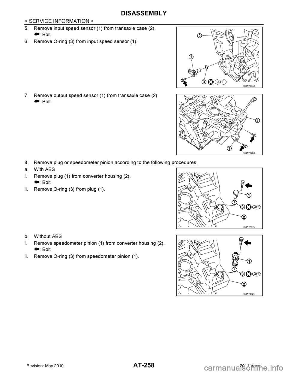
5. Remove input speed sensor (1) from transaxle case (2).: Bolt
6. Remove O-ring (3) from input speed sensor (1).
7. Remove output speed sensor (1) from transaxle case (2). : Bolt
8. Remove plug or speedometer pinion according to the following procedures.
a. With ABS
i. Remove plug (1) from converter housing (2). : Bolt
ii. Remove O-ring (3) from plug (1).
b. Without ABS
i. Remove speedometer pinion (1) from converter housing (2). : Bolt
ii. Remove O-ring (3) from speedometer pinion (1).
SCIA7004J
SCIA7170J
SCIA7747E
SCIA7462E
Revision: May 2010 2011 Versa
Page 293 of 3787
AT-276
< SERVICE INFORMATION >
REPAIR FOR COMPONENT PARTS
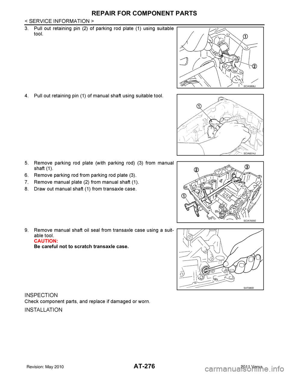
3. Pull out retaining pin (2) of parking rod plate (1) using suitabletool.
4. Pull out retaining pin (1) of manual shaft using suitable tool.
5. Remove parking rod plate (with parking rod) (3) from manual shaft (1).
6. Remove parking rod from parking rod plate (3).
7. Remove manual plate (2) from manual shaft (1).
8. Draw out manual shaft (1) from transaxle case.
9. Remove manual shaft oil seal from transaxle case using a suit- able tool.
CAUTION:
Be careful not to scratch transaxle case.
INSPECTION
Check component parts, and replace if damaged or worn.
INSTALLATION
SCIA5806J
SCIA6514J
SCIA7005E
SAT080D
Revision: May 2010 2011 Versa
Page 294 of 3787
REPAIR FOR COMPONENT PARTSAT-277
< SERVICE INFORMATION >
DE
F
G H
I
J
K L
M A
B
AT
N
O P
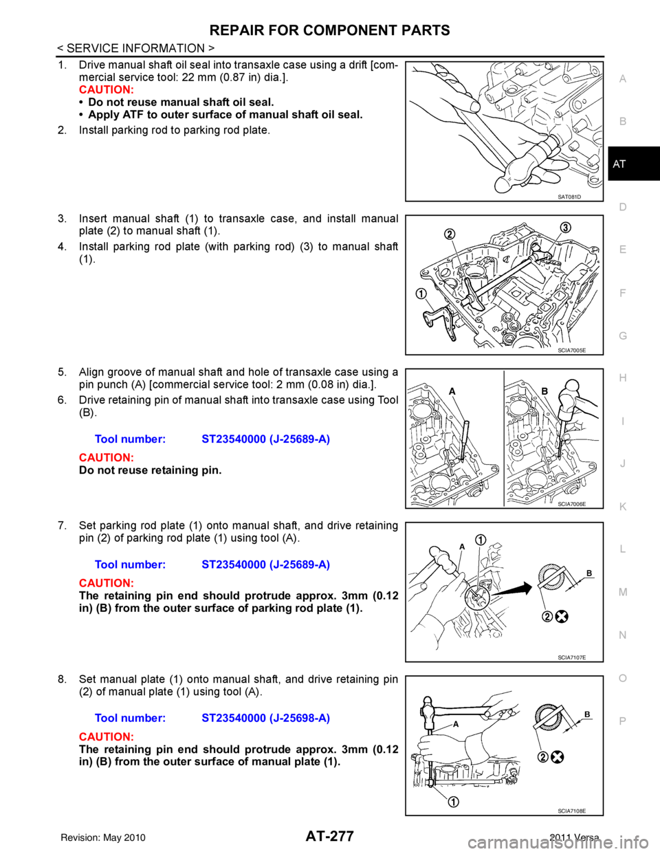
1. Drive manual shaft oil seal into transaxle case using a drift [com- mercial service tool: 22 mm (0.87 in) dia.].
CAUTION:
• Do not reuse manual shaft oil seal.
• Apply ATF to outer surface of manual shaft oil seal.
2. Install parking rod to parking rod plate.
3. Insert manual shaft (1) to transaxle case, and install manual plate (2) to manual shaft (1).
4. Install parking rod plate (with parking rod) (3) to manual shaft (1).
5. Align groove of manual shaft and hole of transaxle case using a pin punch (A) [commercial service tool: 2 mm (0.08 in) dia.].
6. Drive retaining pin of manual shaft into transaxle case using Tool (B).
CAUTION:
Do not reuse retaining pin.
7. Set parking rod plate (1) onto manual shaft, and drive retaining pin (2) of parking rod plate (1) using tool (A).
CAUTION:
The retaining pin end should protrude approx. 3mm (0.12
in) (B) from the outer surface of parking rod plate (1).
8. Set manual plate (1) onto manual shaft, and drive retaining pin (2) of manual plate (1) using tool (A).
CAUTION:
The retaining pin end should protrude approx. 3mm (0.12
in) (B) from the outer surface of manual plate (1).
SAT081D
SCIA7005E
Tool number: ST23540000 (J-25689-A)
SCIA7006E
Tool number: ST23540000 (J-25689-A)
SCIA7107E
Tool number: ST23540000 (J-25698-A)
SCIA7108E
Revision: May 2010 2011 Versa
Page 300 of 3787
REPAIR FOR COMPONENT PARTSAT-283
< SERVICE INFORMATION >
DE
F
G H
I
J
K L
M A
B
AT
N
O P
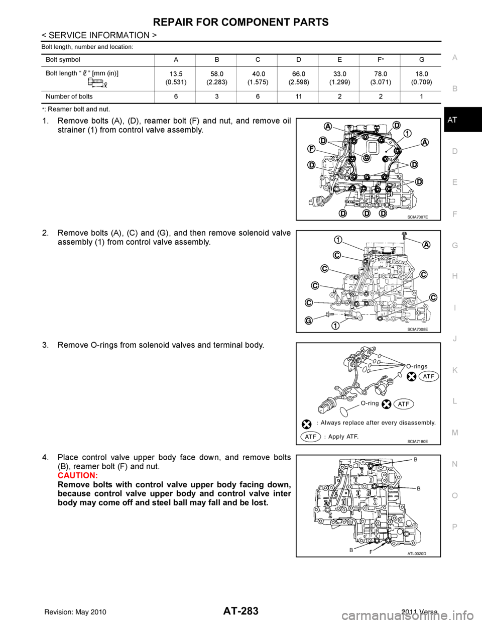
Bolt length, number and location:
*: Reamer bolt and nut.
1. Remove bolts (A), (D), reamer bolt (F) and nut, and remove oil strainer (1) from control valve assembly.
2. Remove bolts (A), (C) and (G), and then remove solenoid valve assembly (1) from control valve assembly.
3. Remove O-rings from solenoid valves and terminal body.
4. Place control valve upper body face down, and remove bolts (B), reamer bolt (F) and nut.
CAUTION:
Remove bolts with control val ve upper body facing down,
because control valve upper body and control valve inter
body may come off and steel ball may fall and be lost.
Bolt symbol ABC D EF*G
Bolt length “ ” [mm (in)] 13.5
(0.531) 58.0
(2.283) 40.0
(1.575) 66.0
(2.598) 33.0
(1.299) 78.0
(3.071) 18.0
(0.709)
Number of bolts 63 611 221
SCIA7007E
SCIA7008E
SCIA7180E
ATL0020D
Revision: May 2010 2011 Versa
Page 301 of 3787
AT-284
< SERVICE INFORMATION >
REPAIR FOR COMPONENT PARTS
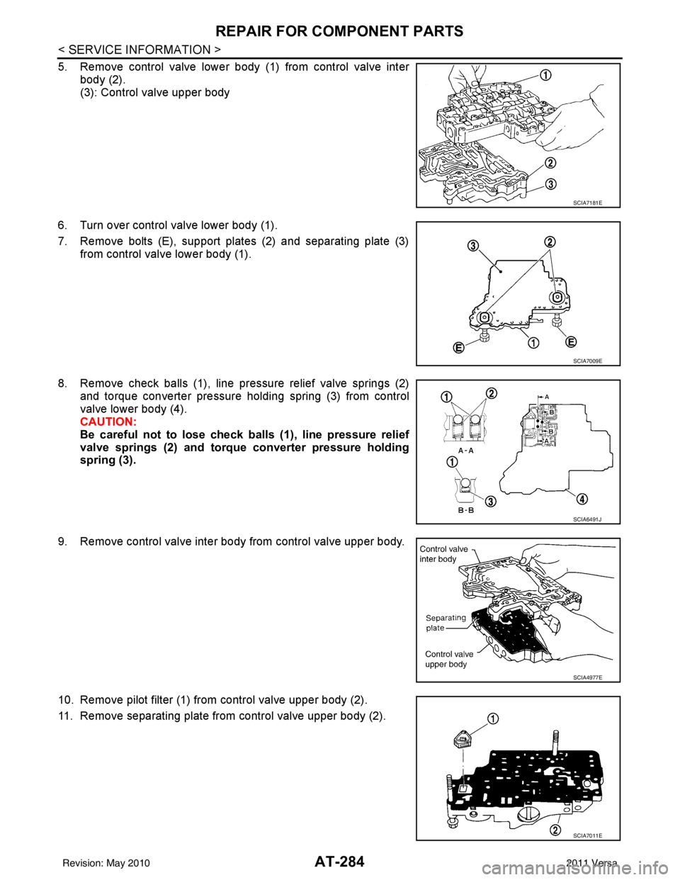
5. Remove control valve lower body (1) from control valve interbody (2).
(3): Control valve upper body
6. Turn over control valve lower body (1).
7. Remove bolts (E), support plates (2) and separating plate (3) from control valve lower body (1).
8. Remove check balls (1), line pressure relief valve springs (2) and torque converter pressure holding spring (3) from control
valve lower body (4).
CAUTION:
Be careful not to lose check ba lls (1), line pressure relief
valve springs (2) and torque converter pressure holding
spring (3).
9. Remove control valve inter body from control valve upper body.
10. Remove pilot filter (1) from control valve upper body (2).
11. Remove separating plate from control valve upper body (2).
SCIA7181E
SCIA7009E
SCIA6491J
SCIA4977E
SCIA7011E
Revision: May 2010 2011 Versa
Page 306 of 3787
REPAIR FOR COMPONENT PARTSAT-289
< SERVICE INFORMATION >
DE
F
G H
I
J
K L
M A
B
AT
N
O P
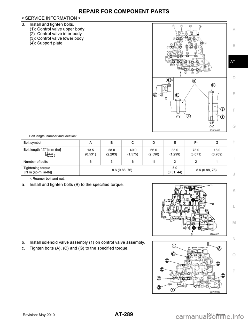
3. Install and tighten bolts. (1): Control valve upper body
(2): Control valve inter body
(3): Control valve lower body
(4): Support plate
Bolt length, number and location:
*: Reamer bolt and nut.
a. Install and tighten bolts (B) to the specified torque.
b. Install solenoid valve assembly (1) on control valve assembly.
c. Tighten bolts (A), (C) and (G) to the specified torque.
SCIA7058E
Bolt symbol ABC D EF*G
Bolt length “ ” [mm (in)] 13.5
(0.531) 58.0
(2.283) 40.0
(1.575) 66.0
(2.598) 33.0
(1.299) 78.0
(3.071) 18.0
(0.709)
Number of bolts 63 611 221
Tightening torque
[N·m (kg-m, in-lb)] 8.6 (0.88, 76)5.0
(0.51, 44) 8.6 (0.88, 76)
ATL0032D
SCIA7008E
Revision: May 2010
2011 Versa
Page 318 of 3787
REPAIR FOR COMPONENT PARTSAT-301
< SERVICE INFORMATION >
DE
F
G H
I
J
K L
M A
B
AT
N
O P
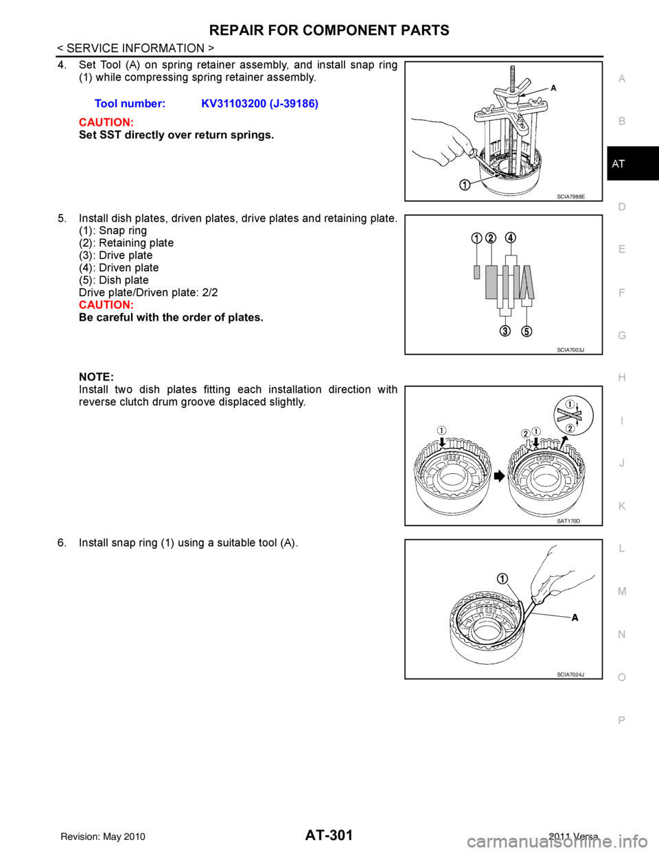
4. Set Tool (A) on spring retainer assembly, and install snap ring (1) while compressing spring retainer assembly.
CAUTION:
Set SST directly over return springs.
5. Install dish plates, driven plates, drive plates and retaining plate. (1): Snap ring
(2): Retaining plate
(3): Drive plate
(4): Driven plate
(5): Dish plate
Drive plate/Driven plate: 2/2
CAUTION:
Be careful with the order of plates.
NOTE:
Install two dish plates fitting each installation direction with
reverse clutch drum groove displaced slightly.
6. Install snap ring (1) using a suitable tool (A). Tool number: KV31103200 (J-39186)
SCIA7988E
SCIA7003J
SAT170D
SCIA7024J
Revision: May 2010
2011 Versa
Page 388 of 3787
ASSEMBLYAT-371
< SERVICE INFORMATION >
DE
F
G H
I
J
K L
M A
B
AT
N
O P
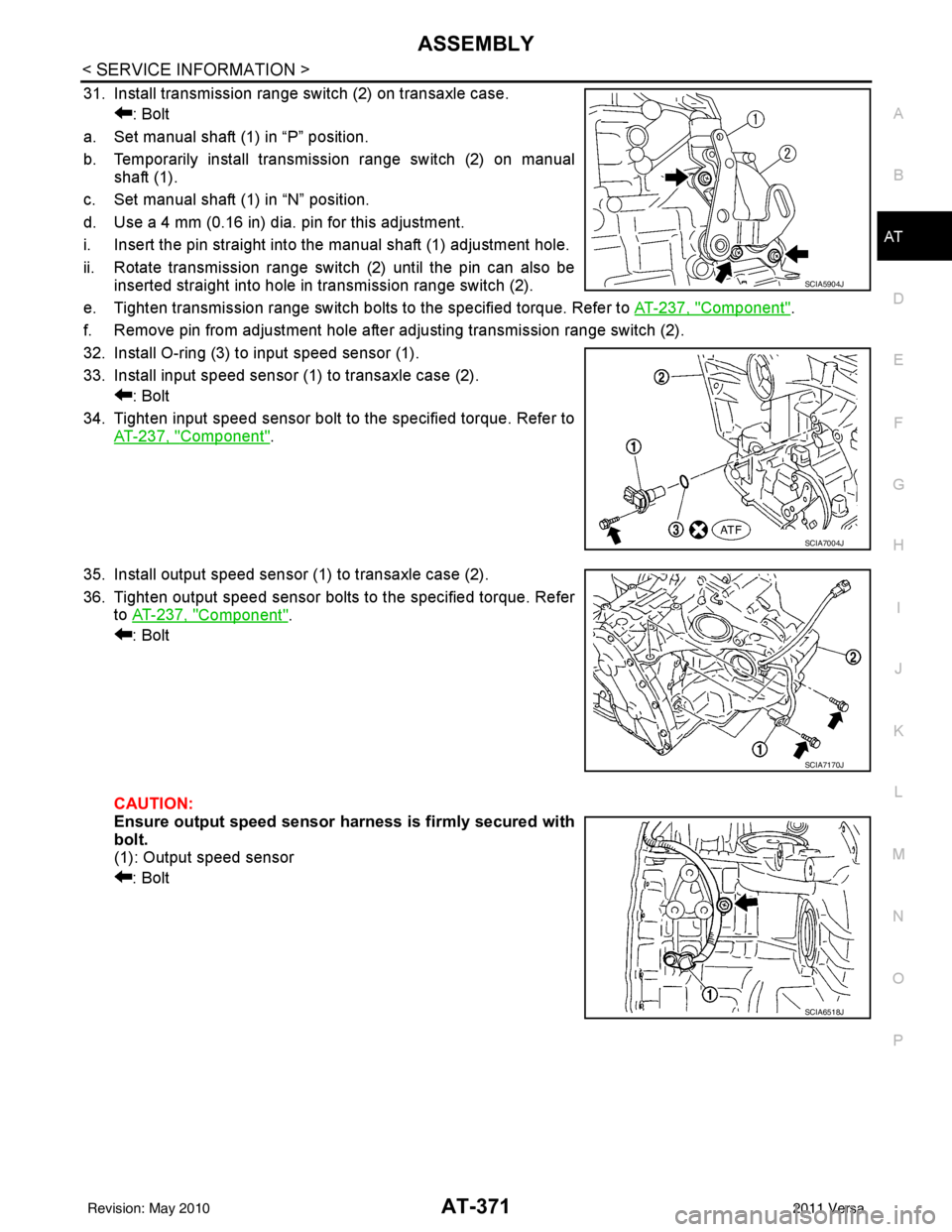
31. Install transmission range switch (2) on transaxle case. : Bolt
a. Set manual shaft (1) in “P” position.
b. Temporarily install transmission range switch (2) on manual shaft (1).
c. Set manual shaft (1) in “N” position.
d. Use a 4 mm (0.16 in) dia. pin for this adjustment.
i. Insert the pin straight into the manual shaft (1) adjustment hole.
ii. Rotate transmission range switch (2) until the pin can also be inserted straight into hole in transmission range switch (2).
e. Tighten transmission range switch bolts to the specified torque. Refer to AT-237, "
Component".
f. Remove pin from adjustment hole after adjusting transmission range switch (2).
32. Install O-ring (3) to input speed sensor (1).
33. Install input speed sensor (1) to transaxle case (2). : Bolt
34. Tighten input speed sensor bolt to the specified torque. Refer to AT-237, "
Component".
35. Install output speed sensor (1) to transaxle case (2).
36. Tighten output speed sensor bolts to the specified torque. Refer to AT-237, "
Component".
: Bolt
CAUTION:
Ensure output speed sensor harness is firmly secured with
bolt.
(1): Output speed sensor
: Bolt
SCIA5904J
SCIA7004J
SCIA7170J
SCIA6518J
Revision: May 2010 2011 Versa