Page 3395 of 3787
REFRIGERANT LINESMTC-79
< SERVICE INFORMATION >
C
DE
F
G H
I
K L
M A
B
MTC
N
O P
1. Use the recovery/recycling equipment to evacuate the refrigerant. Refer to MTC-74, "HFC-134a (R-134a)
Service Procedure".
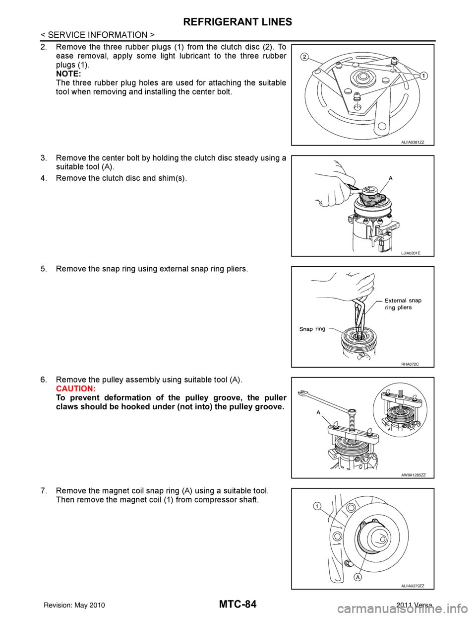
2. Disconnect the low-pressure flexible hose nut (A) and high-pres- sure flexible hose bolt (B) and remove the hoses from compres-
sor.
CAUTION:
Cap or wrap the joint of co mpressor, low-pressure flexible
hose and high-pressure flexible hose with suitable material
such as vinyl tape to avoid the entry of air.
3. Disconnect the compressor harness connector (C)
4. Remove the engine undercover, using power tools.
5. Remove the A/C drive belt. Refer to EM-14, "
Removal and Installation".
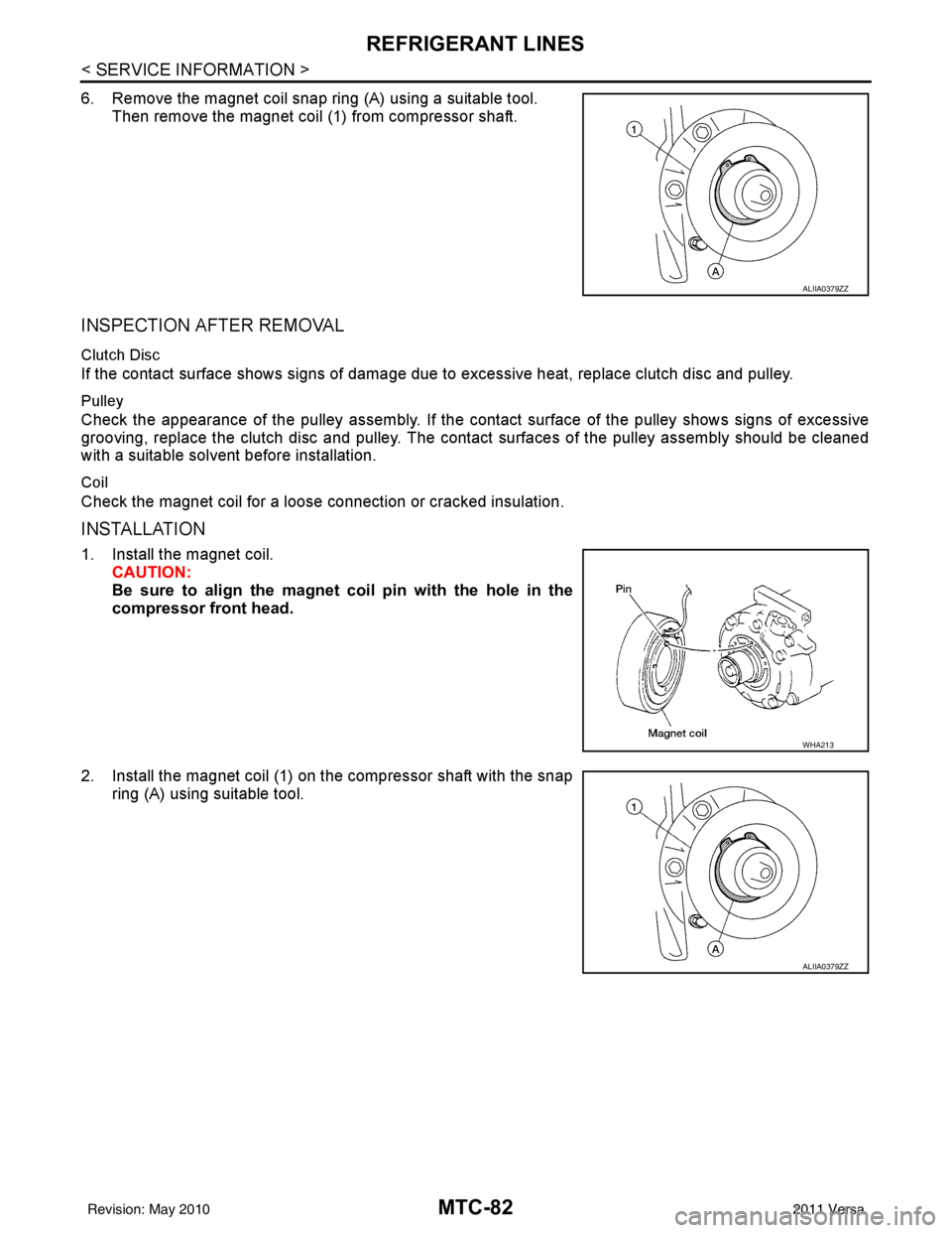
6. Remove the bolts (A) from the compressor (1), using power tools.
7. Remove the compressor (1) downward from the engine com- partment.
INSPECTION FOR CLUTCH DISC TO PULLEY CLEARANCE
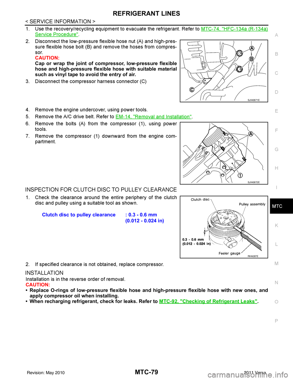
1. Check the clearance around the entire periphery of the clutch
disc and pulley using a suitable tool as shown.
2. If specified clearance is not obtained, replace compressor.
INSTALLATION
Installation is in the reverse order of removal.
CAUTION:
• Replace O-rings of low-pressure flexible hose and high-pressure flexible hose with new ones, and
apply compressor oil when installing.
• When recharging refrigerant, check for leaks. Refer to MTC-92, "
Checking of Refrigerant Leaks".
SJIA0671E
SJIA0672E
Clutch disc to pulley clearance : 0.3 - 0.6 mm
(0.012 - 0.024 in)
RHA087E
Revision: May 2010 2011 Versa
Page 3397 of 3787
REFRIGERANT LINESMTC-81
< SERVICE INFORMATION >
C
DE
F
G H
I
K L
M A
B
MTC
N
O P
INSPECTION FOR CLUTCH DISC TO PULLEY CLEARANCE
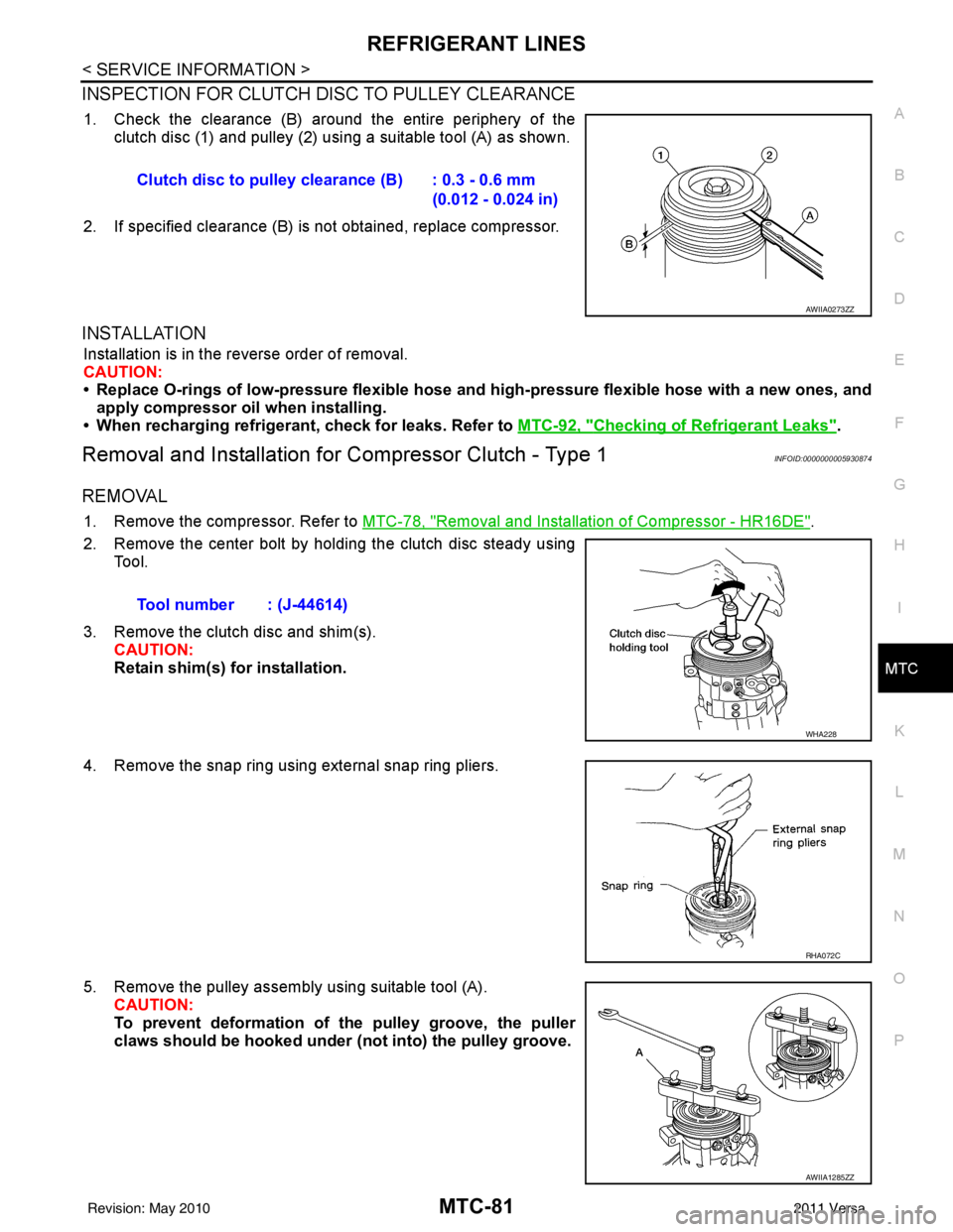
1. Check the clearance (B) around the entire periphery of the clutch disc (1) and pulley (2) usi ng a suitable tool (A) as shown.
2. If specified clearance (B) is not obtained, replace compressor.
INSTALLATION
Installation is in the reverse order of removal.
CAUTION:
• Replace O-rings of low-pressure flexible hose and high-pressure flexible hose with a new ones, and
apply compressor oil when installing.
• When recharging refrigerant, check for leaks. Refer to MTC-92, "
Checking of Refrigerant Leaks".
Removal and Installation for Compressor Clutch - Type 1INFOID:0000000005930874
REMOVAL
1. Remove the compressor. Refer to MTC-78, "Removal and Installation of Compressor - HR16DE".
2. Remove the center bolt by holding the clutch disc steady using Tool.
3. Remove the clutch disc and shim(s). CAUTION:
Retain shim(s) for installation.
4. Remove the snap ring using external snap ring pliers.
5. Remove the pulley assembly using suitable tool (A). CAUTION:
To prevent deformation of the pulley groove, the puller
claws should be hooked under (not into) the pulley groove.
Clutch disc to pulley clearance (B) : 0.3 - 0.6 mm
(0.012 - 0.024 in)
AWIIA0273ZZ
Tool number : (J-44614)
WHA228
RHA072C
AWIIA1285ZZ
Revision: May 2010 2011 Versa
Page 3398 of 3787
MTC-82
< SERVICE INFORMATION >
REFRIGERANT LINES
6. Remove the magnet coil snap ring (A) using a suitable tool.Then remove the magnet coil (1) from compressor shaft.
INSPECTION AFTER REMOVAL
Clutch Disc
If the contact surface shows signs of damage due to excessive heat, replace clutch disc and pulley.
Pulley
Check the appearance of the pulley assembly. If the cont act surface of the pulley shows signs of excessive
grooving, replace the clutch disc and pulley. The contact surfaces of the pulley assembly should be cleaned
with a suitable solvent before installation.
Coil
Check the magnet coil for a loose connection or cracked insulation.
INSTALLATION
1. Install the magnet coil.
CAUTION:
Be sure to align the magnet coil pin with the hole in the
compressor front head.
2. Install the magnet coil (1) on the compressor shaft with the snap ring (A) using suitable tool.
ALIIA0379ZZ
WHA213
ALIIA0379ZZ
Revision: May 2010 2011 Versa
Page 3399 of 3787
REFRIGERANT LINESMTC-83
< SERVICE INFORMATION >
C
DE
F
G H
I
K L
M A
B
MTC
N
O P
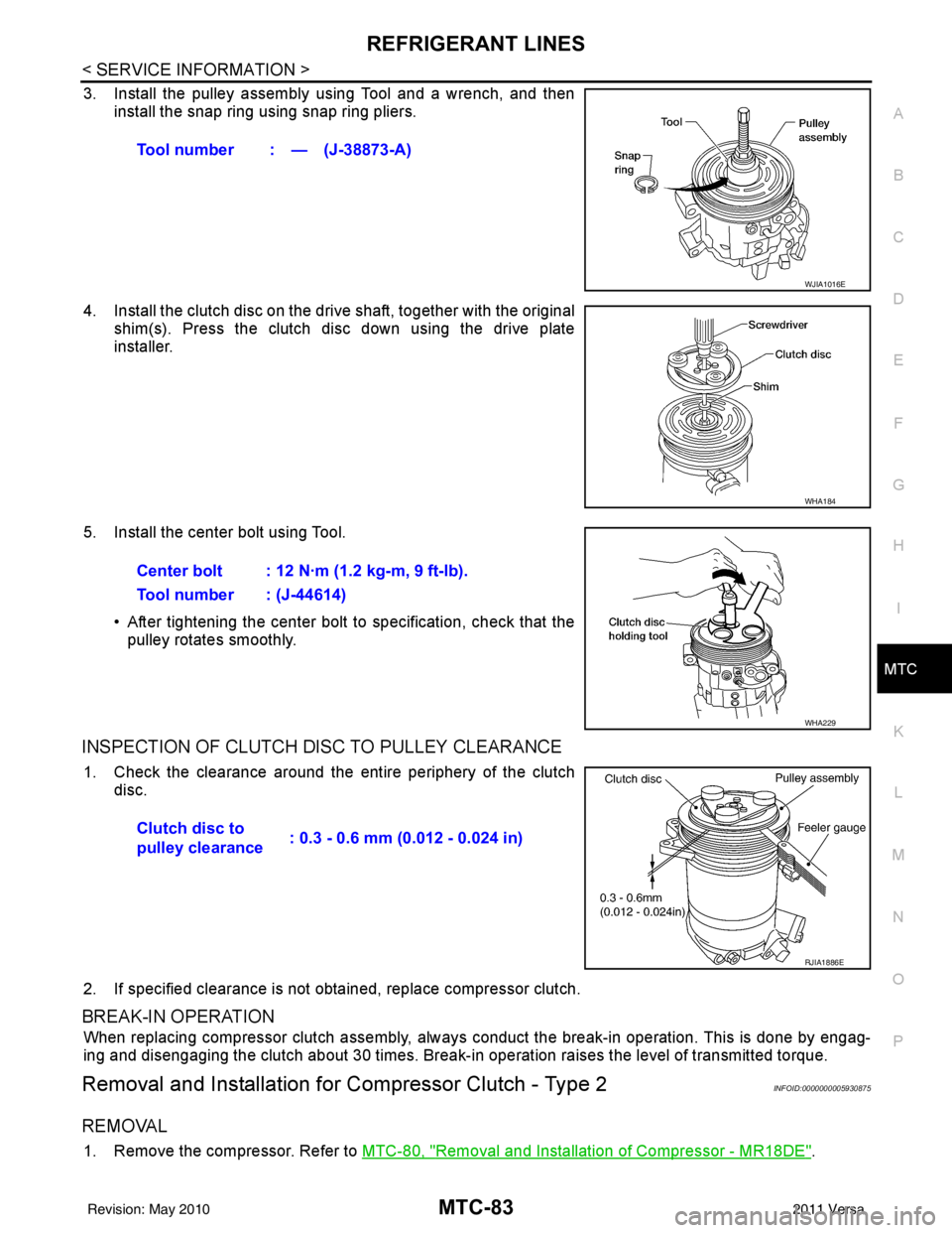
3. Install the pulley assembly using Tool and a wrench, and then install the snap ring using snap ring pliers.
4. Install the clutch disc on the drive shaft, together with the original shim(s). Press the clutch disc down using the drive plate
installer.
5. Install the center bolt using Tool. • After tightening the center bolt to specification, check that thepulley rotates smoothly.
INSPECTION OF CLUTCH DISC TO PULLEY CLEARANCE
1. Check the clearance around the entire periphery of the clutch
disc.
2. If specified clearance is not obt ained, replace compressor clutch.
BREAK-IN OPERATION
When replacing compressor clutch assembly, always conduct the break-in operation. This is done by engag-
ing and disengaging the clutch about 30 times. Break-in operation raises the level of transmitted torque.
Removal and Installation for Compressor Clutch - Type 2INFOID:0000000005930875
REMOVAL
1. Remove the compressor. Refer to MTC-80, "Removal and Installation of Compressor - MR18DE".
Tool number : — (J-38873-A)
WJIA1016E
WHA184
Center bolt : 12 N·m (1.2 kg-m, 9 ft-lb).
Tool number : (J-44614)
WHA229
Clutch disc to
pulley clearance
: 0.3 - 0.6 mm (0.012 - 0.024 in)
RJIA1886E
Revision: May 2010
2011 Versa
Page 3400 of 3787
MTC-84
< SERVICE INFORMATION >
REFRIGERANT LINES
2. Remove the three rubber plugs (1) from the clutch disc (2). Toease removal, apply some light lubricant to the three rubber
plugs (1).
NOTE:
The three rubber plug holes are used for attaching the suitable
tool when removing and installing the center bolt.
3. Remove the center bolt by holding the clutch disc steady using a suitable tool (A).
4. Remove the clutch disc and shim(s).
5. Remove the snap ring using external snap ring pliers.
6. Remove the pulley assembly using suitable tool (A). CAUTION:
To prevent deformation of th e pulley groove, the puller
claws should be ho oked under (not into) the pulley groove.
7. Remove the magnet coil snap ring (A) using a suitable tool. Then remove the magnet coil (1) from compressor shaft.
ALIIA0381ZZ
LJIA0201E
RHA072C
AWIIA1285ZZ
ALIIA0379ZZ
Revision: May 2010 2011 Versa
Page 3401 of 3787
REFRIGERANT LINESMTC-85
< SERVICE INFORMATION >
C
DE
F
G H
I
K L
M A
B
MTC
N
O P
INSPECTION AFTER REMOVAL
Clutch Disc
If the contact surface shows signs of damage due to excessive heat, replace clutch disc and pulley.
Pulley
Check the appearance of the pulley assembly. If the cont act surface of the pulley shows signs of excessive
grooving, replace the clutch disc and pulley. The c ontact surfaces of the pulley assembly should be cleaned
with a suitable solvent before installation.
Coil
Check the magnet coil for a loose connection or cracked insulation.
INSTALLATION
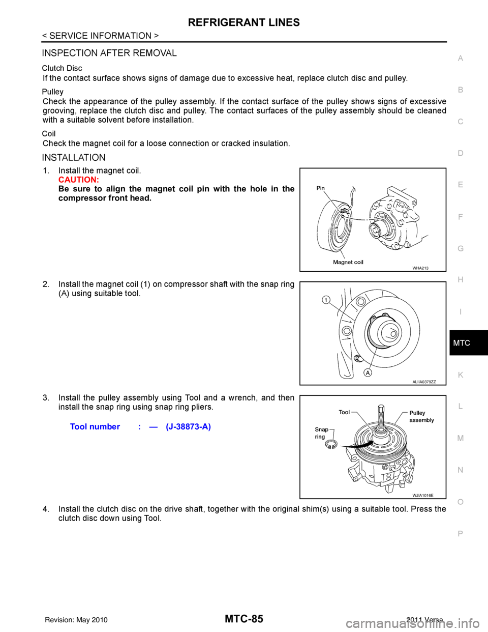
1. Install the magnet coil. CAUTION:
Be sure to align the magnet coil pin with the hole in the
compressor front head.
2. Install the magnet coil (1) on compressor shaft with the snap ring (A) using suitable tool.
3. Install the pulley assembly using Tool and a wrench, and then install the snap ring using snap ring pliers.
4. Install the clutch disc on the drive shaft, together with the original shim(s) using a suitable tool. Press the
clutch disc down using Tool.
WHA213
ALIIA0379ZZ
Tool number : — (J-38873-A)
WJIA1016E
Revision: May 2010 2011 Versa
Page 3402 of 3787
MTC-86
< SERVICE INFORMATION >
REFRIGERANT LINES
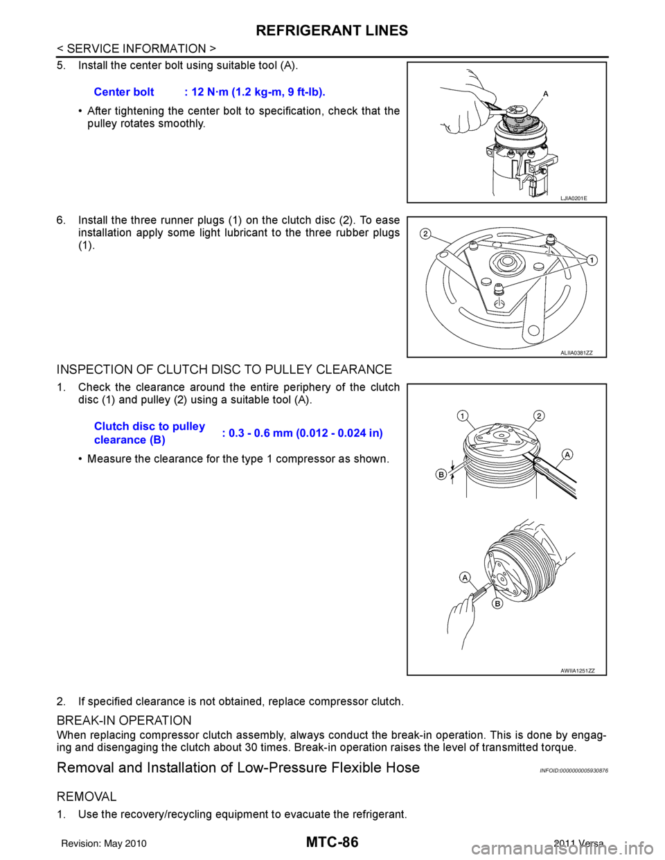
5. Install the center bolt using suitable tool (A).• After tightening the center bolt to specification, check that the
pulley rotates smoothly.
6. Install the three runner plugs (1) on the clutch disc (2). To ease installation apply some light lubricant to the three rubber plugs
(1).
INSPECTION OF CLUTCH DISC TO PULLEY CLEARANCE
1. Check the clearance around the entire periphery of the clutchdisc (1) and pulley (2) using a suitable tool (A).
• Measure the clearance for the type 1 compressor as shown.
2. If specified clearance is not obtained, replace compressor clutch.
BREAK-IN OPERATION
When replacing compressor clutch assembly, always conduct the break-in operation. This is done by engag-
ing and disengaging the clutch about 30 times. Break-in operation raises the level of transmitted torque.
Removal and Installation of Low-Pressure Flexible HoseINFOID:0000000005930876
REMOVAL
1. Use the recovery/recycling equipment to evacuate the refrigerant.Center bolt : 12 N·m (1.2 kg-m, 9 ft-lb).
LJIA0201E
ALIIA0381ZZ
Clutch disc to pulley
clearance (B)
: 0.3 - 0.6 mm (0.012 - 0.024 in)
AWIIA1251ZZ
Revision: May 2010
2011 Versa
Page 3604 of 3787
SC-26
< SERVICE INFORMATION >
CHARGING SYSTEM
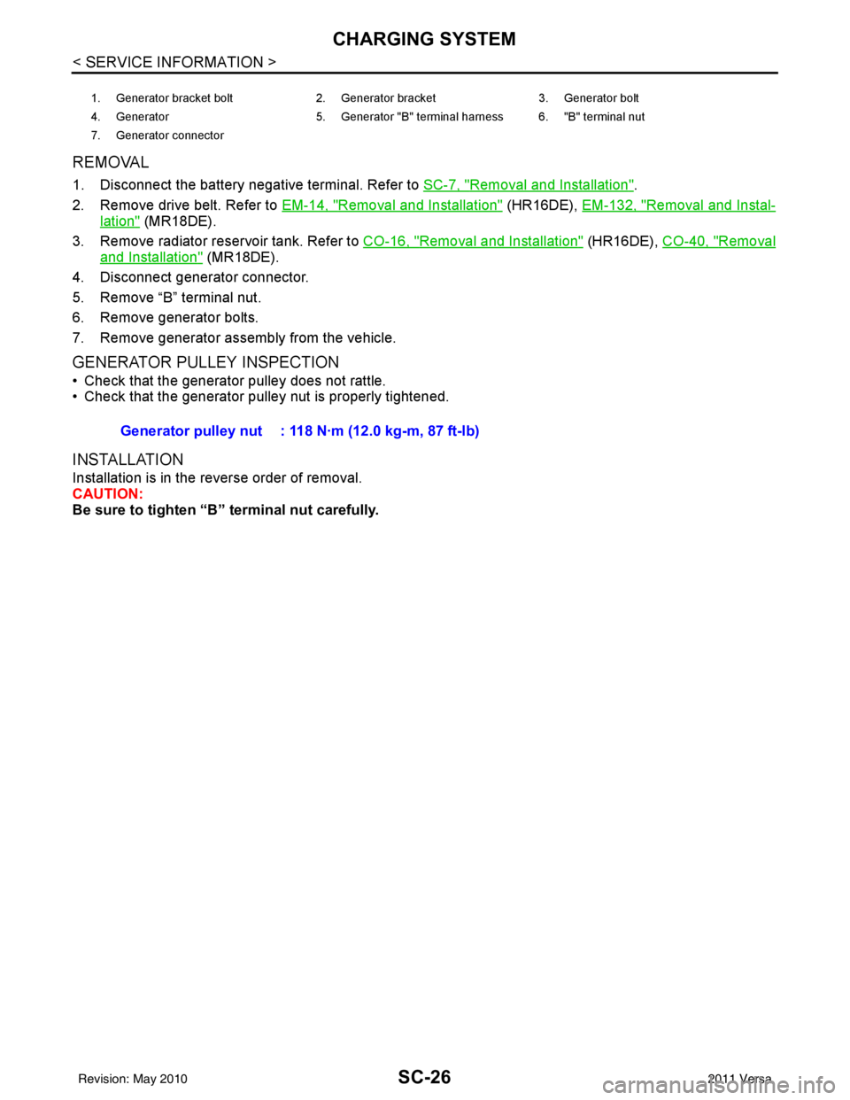
REMOVAL
1. Disconnect the battery negative terminal. Refer to SC-7, "Removal and Installation".
2. Remove drive belt. Refer to EM-14, "
Removal and Installation" (HR16DE), EM-132, "Removal and Instal-
lation" (MR18DE).
3. Remove radiator reservoir tank. Refer to CO-16, "
Removal and Installation" (HR16DE), CO-40, "Removal
and Installation" (MR18DE).
4. Disconnect generator connector.
5. Remove “B” terminal nut.
6. Remove generator bolts.
7. Remove generator assembly from the vehicle.
GENERATOR PULLEY INSPECTION
• Check that the generator pulley does not rattle.
• Check that the generator pulley nut is properly tightened.
INSTALLATION
Installation is in the reverse order of removal.
CAUTION:
Be sure to tighten “B” terminal nut carefully.
1. Generator bracket bolt 2. Generator bracket3. Generator bolt
4. Generator 5. Generator "B" terminal harness 6. "B" terminal nut
7. Generator connector
Generator pulley nut : 118 N·m (12.0 kg-m, 87 ft-lb)
Revision: May 2010 2011 Versa