2011 NISSAN TIIDA Engine front side
[x] Cancel search: Engine front sidePage 2546 of 3787
EM-156
< SERVICE INFORMATION >[MR18DE]
FUEL INJECTOR AND FUEL TUBE
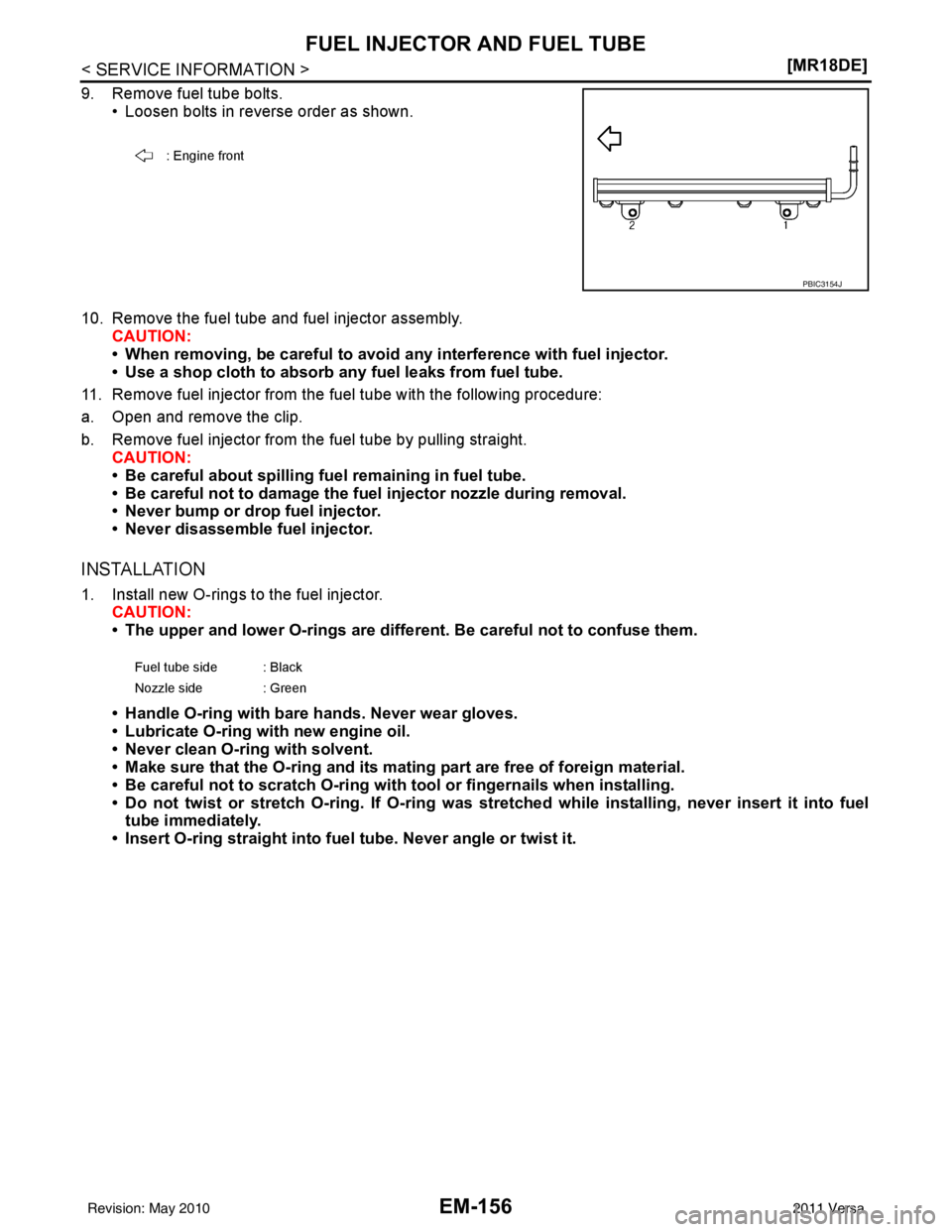
9. Remove fuel tube bolts.
• Loosen bolts in reverse order as shown.
10. Remove the fuel tube and fuel injector assembly. CAUTION:
• When removing, be careful to avoid any interference with fuel injector.
• Use a shop cloth to absorb any fuel leaks from fuel tube.
11. Remove fuel injector from the f uel tube with the following procedure:
a. Open and remove the clip.
b. Remove fuel injector from the fuel tube by pulling straight. CAUTION:
• Be careful about spilling fu el remaining in fuel tube.
• Be careful not to damage the fuel injector nozzle during removal.
• Never bump or drop fuel injector.
• Never disassemble fuel injector.
INSTALLATION
1. Install new O-rings to the fuel injector.
CAUTION:
• The upper and lower O-rings are different. Be careful not to confuse them.
• Handle O-ring with bare hands. Never wear gloves.
• Lubricate O-ring with new engine oil.
• Never clean O-ring with solvent.
• Make sure that the O-ring and its mati ng part are free of foreign material.
• Be careful not to scratch O-ring with tool or fingernails when installing.
• Do not twist or stretch O-ring. If O-ring was stretched while installing, never insert it into fuel
tube immediately.
• Insert O-ring straight into fuel tube. Never angle or twist it.
: Engine front
PBIC3154J
Fuel tube side : Black
Nozzle side : Green
Revision: May 2010 2011 Versa
Page 2553 of 3787
TIMING CHAINEM-163
< SERVICE INFORMATION > [MR18DE]
C
D
E
F
G H
I
J
K L
M A
EM
NP
O
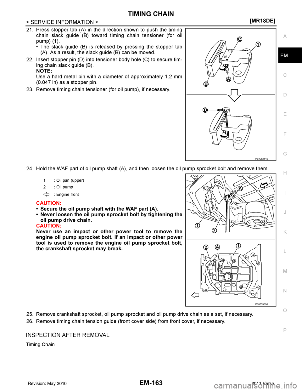
21. Press stopper tab (A) in the direction shown to push the timing
chain slack guide (B) toward ti ming chain tensioner (for oil
pump) (1).
• The slack guide (B) is released by pressing the stopper tab
(A). As a result, the slack guide (B) can be moved.
22. Insert stopper pin (D) into tensioner body hole (C) to secure tim- ing chain slack guide (B).
NOTE:
Use a hard metal pin with a diameter of approximately 1.2 mm
(0.047 in) as a stopper pin.
23. Remove timing chain tensioner (for oil pump), if necessary.
24. Hold the WAF part of oil pump shaft (A), and then loosen the oil pump sprocket bolt and remove them. CAUTION:
• Secure the oil pump shaft with the WAF part (A).
• Never loosen the oil pump sprocket bolt by tightening theoil pump drive chain.
CAUTION:
Never use an impact or other power tool to remove the
engine oil pump sprocket bolt. If an impact or other power
tool is used to remove the e ngine oil pump sprocket bolt,
the crankshaft sprocket may break.
25. Remove crankshaft sprocket, oil pump sprocket and oil pump drive chain as a set, if necessary.
26. Remove timing chain tension guide (front cover side) from front cover, if necessary.
INSPECTION AFTER REMOVAL
Timing Chain
PBIC5314E
1 : Oil pan (upper)
2: Oil pump
: Engine front
PBIC3539J
Revision: May 2010 2011 Versa
Page 2557 of 3787
TIMING CHAINEM-167
< SERVICE INFORMATION > [MR18DE]
C
D
E
F
G H
I
J
K L
M A
EM
NP
O
9. Check matching mark position of timing chain and each sprocket again.
10. Apply new engine oil to new front oil seal joint surface.
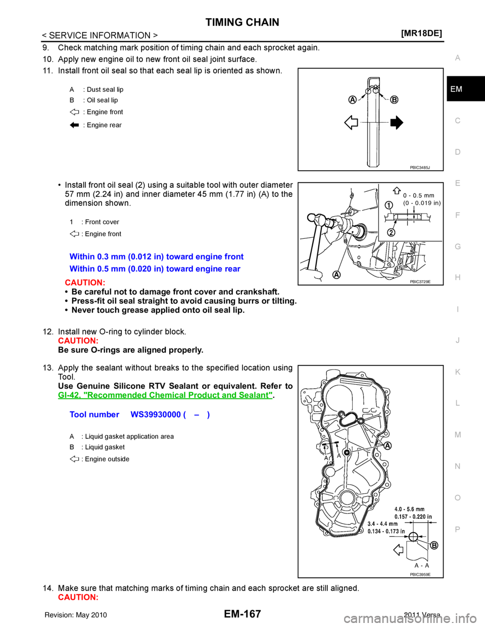
11. Install front oil seal so that each seal lip is oriented as shown.
• Install front oil seal (2) using a suitable tool with outer diameter57 mm (2.24 in) and inner diameter 45 mm (1.77 in) (A) to the
dimension shown.
CAUTION:
• Be careful not to damage front cover and crankshaft.
• Press-fit oil seal straight to avoid causing burrs or tilting.
• Never touch grease applied onto oil seal lip.
12. Install new O-ring to cylinder block. CAUTION:
Be sure O-rings are aligned properly.
13. Apply the sealant without breaks to the specified location using Tool.
Use Genuine Silicone RTV Seal ant or equivalent. Refer to
GI-42, "
Recommended Chemical Product and Sealant".
14. Make sure that matching marks of timi ng chain and each sprocket are still aligned.
CAUTION:
A : Dust seal lip
B: Oil seal lip
: Engine front
: Engine rear
PBIC3485J
1 : Front cover: Engine front
Within 0.3 mm (0.012 in) toward engine front
Within 0.5 mm (0.020 in) toward engine rear
PBIC3729E
Tool number WS39930000 ( – )
A : Liquid gasket application area
B : Liquid gasket
: Engine outside
PBIC3959E
Revision: May 2010 2011 Versa
Page 2565 of 3787
CAMSHAFTEM-175
< SERVICE INFORMATION > [MR18DE]
C
D
E
F
G H
I
J
K L
M A
EM
NP
O
• Clean camshaft journal to remove any foreign material.
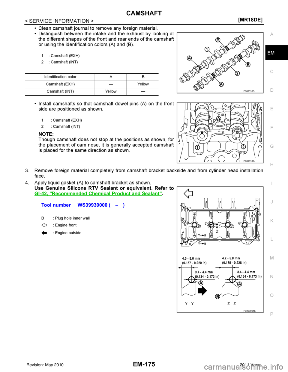
• Distinguish between the intake and the exhaust by looking at
the different shapes of the front and rear ends of the camshaft
or using the identification colors (A) and (B).
• Install camshafts so that camshaft dowel pins (A) on the front side are positioned as shown.
NOTE:
Though camshaft does not stop at t he positions as shown, for
the placement of cam nose, it is generally accepted camshaft
is placed for the same direction as shown.
3. Remove foreign material completely from camshaft bracket backside and from cylinder head installation face.
4. Apply liquid gasket (A) to camshaft bracket as shown. Use Genuine Silicone RTV Seal ant or equivalent. Refer to
GI-42, "
Recommended Chemical Product and Sealant".
1 : Camshaft (EXH)
2 : Camshaft (INT)
Identification color AB
Camshaft (EXH) —Yellow
Camshaft (INT) Yellow—
PBIC3188J
1 : Camshaft (EXH)
2 : Camshaft (INT)
PBIC3189J
Tool number WS39930000 ( – )
B : Plug hole inner wall
: Engine front
: Engine outside
PBIC3964E
Revision: May 2010 2011 Versa
Page 2569 of 3787
CAMSHAFTEM-179
< SERVICE INFORMATION > [MR18DE]
C
D
E
F
G H
I
J
K L
M A
EM
NP
O
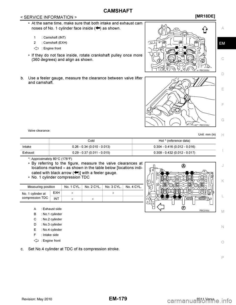
• At the same time, make sure that both intake and exhaust cam
noses of No. 1 cylinder face inside ( ) as shown.
• If they do not face inside, rotate crankshaft pulley once more (360 degrees) and align as shown.
b. Use a feeler gauge, measure the clearance between valve lifter and camshaft.
Valve clearance:
Unit: mm (in)
*: Approximately 80°C (176 °F)
• By referring to the figure, measure the valve clearances at
locations marked × as shown in the table below [locations indi-
cated with black arrow ( )] with a feeler gauge.
• No. 1 cylinder compression TDC
c. Set No.4 cylinder at TDC of its compression stroke.
1 : Camshaft (INT)
2 : Camshaft (EXH) : Engine front
PBIC3359J
PBIC3192J
Cold Hot * (reference data)
Intake 0.26 - 0.34 (0.010 - 0.013) 0.304 - 0.416 (0.012 - 0.016)
Exhaust 0.29 - 0.37 (0.011 - 0.015) 0.308 - 0.432 (0.012 - 0.017)
Measuring position No. 1 CYL. No. 2 CYL. No. 3 CYL. No. 4 CYL.
No. 1 cylinder at
compression TDC EXH
× ×
INT × ×
A : Exhaust side
B : No.1 cylinder
C : No.2 cylinder
D : No.3 cylinder
E : No.4 cylinder
F : Intake side : Engine front
PBIC3193J
Revision: May 2010 2011 Versa
Page 2570 of 3787
EM-180
< SERVICE INFORMATION >[MR18DE]
CAMSHAFT
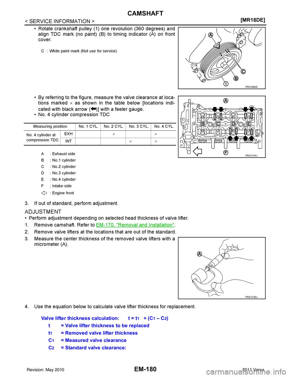
• Rotate crankshaft pulley (1) one revolution (360 degrees) and
align TDC mark (no paint) (B) to timing indicator (A) on front
cover.
• By referring to the figure, measure the valve clearance at loca- tions marked × as shown in the table below [locations indi-
cated with black arrow ( )] with a feeler gauge.
• No. 4 cylinder compression TDC
3. If out of standard, perform adjustment.
ADJUSTMENT
• Perform adjustment depending on selected head thickness of valve lifter.
1. Remove camshaft. Refer to EM-170, "
Removal and Installation".
2. Remove valve lifters at the locations that are out of the standard.
3. Measure the center thickness of the removed valve lifters with a micrometer (A).
4. Use the equation below to calculate valve lifter thickness for replacement.
C : White paint mark (Not use for service)
PBIC3960E
Measuring position No. 1 CYL. No. 2 CYL. No. 3 CYL. No. 4 CYL.
No. 4 cylinder at
compression TDC EXH
× ×
INT × ×
A : Exhaust side
B : No.1 cylinder
C : No.2 cylinder
D : No.3 cylinder
E : No.4 cylinder
F: Intake side : Engine front
PBIC3194J
PBIC3195J
Valve lifter thickness calculation: t = t1 + (C1 – C2)
t = Valve lifter thickness to be replaced
t
1 = Removed valve lifter thickness
C
1= Measured valve clearance
C
2= Standard valve clearance:
Revision: May 2010 2011 Versa
Page 2588 of 3787
EM-198
< SERVICE INFORMATION >[MR18DE]
ENGINE ASSEMBLY
• Use either 2-pole lift type or separate type lift as
best you can. If board-on type is used for unavoid-
able reasons, support at the rear axle jacking point with a transmission jack or similar tool before
starting work, in preparation for the backward shift of center of gravity.
• For supporting points for lifting and jacking point at rear axle, refer to GI-38, "
Garage Jack and
Safety Stand and 2-Pole Lift".
REMOVAL
Remove the engine and the transaxle assembly from t he vehicle downward. Separate the engine and the tran-
saxle.
1. Remove engine under cover. Refer to EI-15, "
Removal and Installation".
2. Drain engine coolant from radiator. Refer to CO-36, "
Changing Engine Coolant".
CAUTION:
• Perform this step when the engine is cold.
• Do not spill engine coolant on drive belt.
3. Drain clutch fluid (M/T models). Refer to CL-9, "
Air Bleeding Procedure".
4. Remove front fender protector (RH and LH). Refer to EI-26
.
5. Remove exhaust front tube. Refer to EX-10
.
6. Remove drive shafts (LH and RH) from steering knuckle. Refer to FA X - 9
.
7. Remove transaxle joint bolts which pierce at oil pan (upper) lower rear side. Refer to AT-233
(A/T models),
CVT-180, "
Removal and Installation" (CVT models) or MT-61, "Removal and Installation" (M/T models).
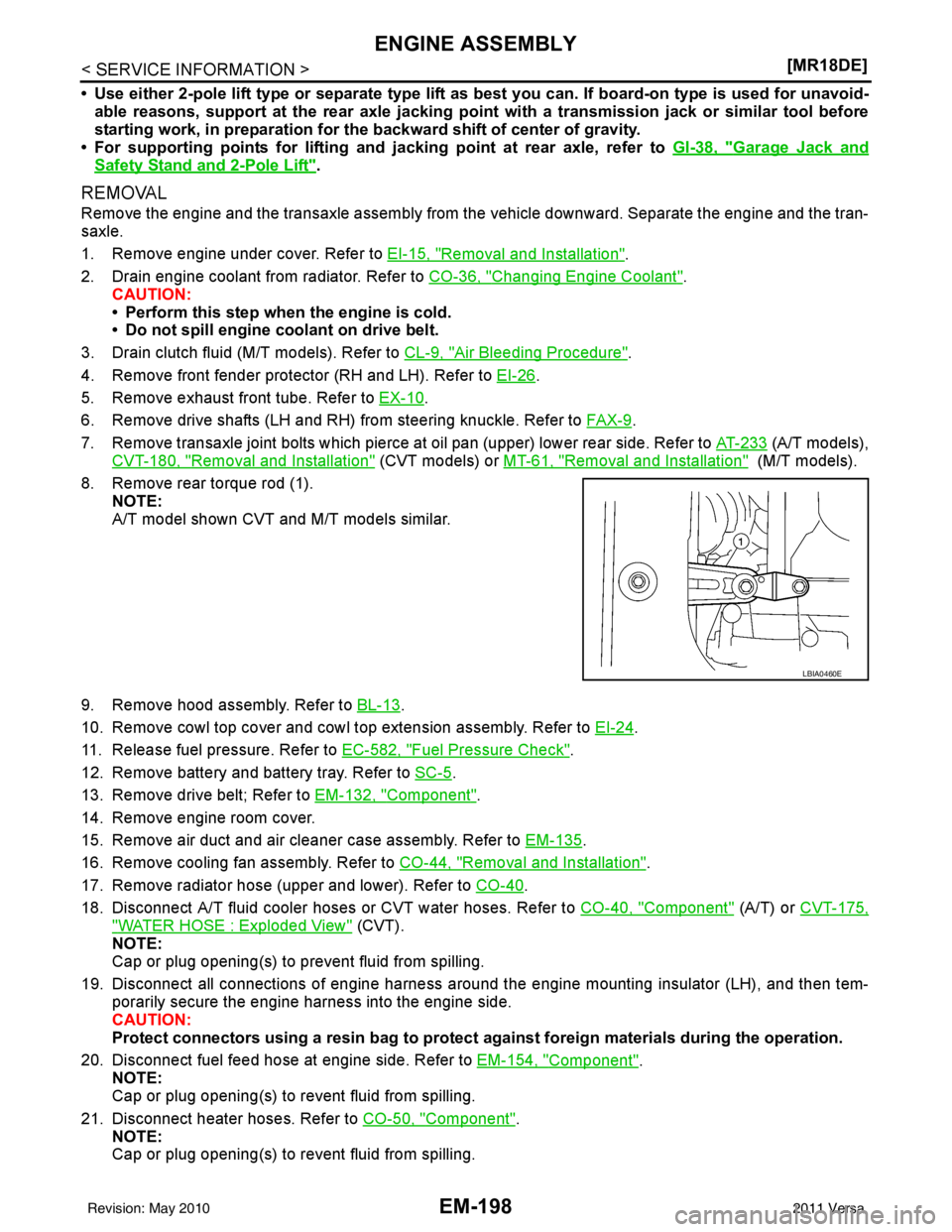
8. Remove rear torque rod (1). NOTE:
A/T model shown CVT and M/T models similar.
9. Remove hood assembly. Refer to BL-13
.
10. Remove cowl top cover and cowl top extension assembly. Refer to EI-24
.
11. Release fuel pressure. Refer to EC-582, "
Fuel Pressure Check".
12. Remove battery and battery tray. Refer to SC-5
.
13. Remove drive belt; Refer to EM-132, "
Component".
14. Remove engine room cover.
15. Remove air duct and air cleaner case assembly. Refer to EM-135
.
16. Remove cooling fan assembly. Refer to CO-44, "
Removal and Installation".
17. Remove radiator hose (upper and lower). Refer to CO-40
.
18. Disconnect A/T fluid cooler hoses or CVT water hoses. Refer to CO-40, "
Component" (A/T) or CVT-175,
"WATER HOSE : Exploded View" (CVT).
NOTE:
Cap or plug opening(s) to prevent fluid from spilling.
19. Disconnect all connections of engine harness around the engine mounting insulator (LH), and then tem- porarily secure the engine harness into the engine side.
CAUTION:
Protect connectors using a resin bag to protect against foreign materials during the operation.
20. Disconnect fuel feed hose at engine side. Refer to EM-154, "
Component".
NOTE:
Cap or plug opening(s) to revent fluid from spilling.
21. Disconnect heater hoses. Refer to CO-50, "
Component".
NOTE:
Cap or plug opening(s) to revent fluid from spilling.
LBIA0460E
Revision: May 2010 2011 Versa
Page 2589 of 3787
ENGINE ASSEMBLYEM-199
< SERVICE INFORMATION > [MR18DE]
C
D
E
F
G H
I
J
K L
M A
EM
NP
O
22. Disconnect control cable from transaxle. Refer to
CVT-180, "Removal and Installation" (CVT models), AT-
213 (A/T models) or MT-61, "Removal and Installation" (M/T models).
23. Remove ground cable at transaxle side.
24. Remove ground cable between front cover and vehicle.
25. Remove generator. Refer to SC-21
.
26. Remove A/C compressor with piping connected from t he engine. Temporarily secure it on the vehicle side
with a rope to avoid putting load on it. Refer to MTC-80, "
Removal and Installation of Compressor -
MR18DE".
27. Remove the intake manifold to prevent the hanging chain from interfering. Refer to EM-137, "
Compo-
nent".
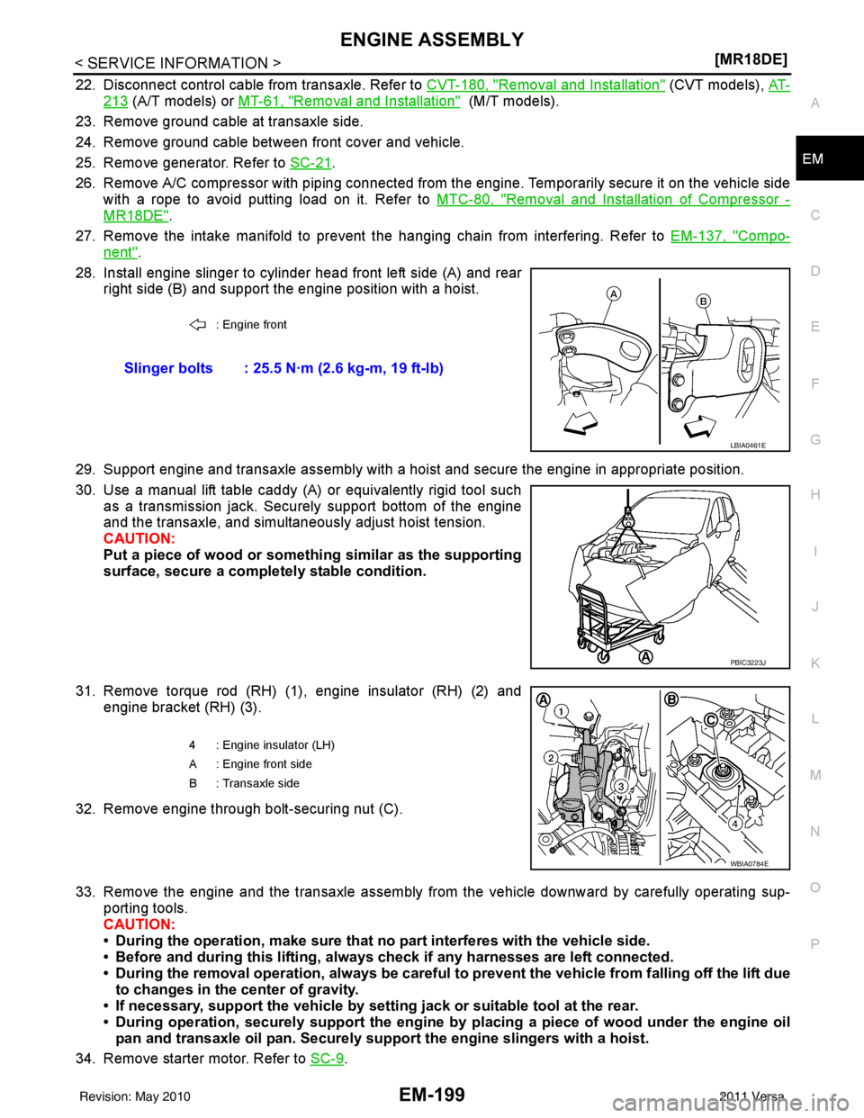
28. Install engine slinger to cylinder head front left side (A) and rear right side (B) and support the engine position with a hoist.
29. Support engine and transaxle assembly with a hoist and secure the engine in appropriate position.
30. Use a manual lift table caddy (A) or equivalently rigid tool such as a transmission jack. Securely support bottom of the engine
and the transaxle, and simultaneously adjust hoist tension.
CAUTION:
Put a piece of wood or someth ing similar as the supporting
surface, secure a completely stable condition.
31. Remove torque rod (RH) (1), engine insulator (RH) (2) and engine bracket (RH) (3).
32. Remove engine through bolt-securing nut (C).
33. Remove the engine and the transaxle assembly from the vehicle downward by carefully operating sup- porting tools.
CAUTION:
• During the operation, make sure that no part interferes with the vehicle side.
• Before and during this lifting, alw ays check if any harnesses are left connected.
• During the removal operation, alw ays be careful to prevent the vehicle from falling off the lift due
to changes in the center of gravity.
• If necessary, support the vehicle by setting jack or suitable tool at the rear.
• During operation, securely suppor t the engine by placing a piece of wood under the engine oil
pan and transaxle oil pan. Securely sup port the engine slingers with a hoist.
34. Remove starter motor. Refer to SC-9
.
: Engine front
Slinger bolts : 25.5 N·m (2.6 kg-m, 19 ft-lb)
LBIA0461E
PBIC3223J
4 : Engine insulator (LH)
A : Engine front side
B : Transaxle side
WBIA0784E
Revision: May 2010 2011 Versa