2011 NISSAN TIIDA ECO mode
[x] Cancel search: ECO modePage 887 of 3787

BR-40
< SERVICE INFORMATION >
SERVICE DATA AND SPECIFICATIONS (SDS)
SERVICE DATA AND SPECIFICATIONS (SDS)
General SpecificationINFOID:0000000005928420
HR16DE
MR18DE
TypeWith ABS or VDC/TCS/ABSWithout ABS
Front brake Brake model AD22VK
Cylinder bore diameter 53.97 mm (2.125 in)
Pad
Length × width × thickness 115.0 mm ×
41.0 mm × 9.0 mm
(4.528 in × 1.614 in × 0.354 in)
Rotor outer diameter × thickness 260 mm × 22.0 mm (10.24 in × 0.866 in)
Rear brake Brake model LT20
Cylinder bore diameter 15.87 mm (0.625 in)17.46 mm (0.687 in)
Drum inner diameter 203 mm (7.992 in)
Master cylinder Cylinder bore diameter 22.22 mm (0.875 in)
Brake booster Booster model C255
Diaphragm diameter 255 mm (10.04 in)
Recommended brake fluid DOT 3
Front brake Brake modelCLZ25VF
Cylinder bore diameter 57.2 mm (2.252 in)
Pad
Length × width × thickness 125.6 mm
× 48.0 mm × 9.5 mm
(4.945 in × 1.890 in × 0.374 in)
Rotor outer diameter × thickness 280 mm × 24.0 mm (11.02 in × 0.945 in)
Rear brake Brake model LT23
Cylinder bore diameter 19.06 mm (0.750 in)
Drum inner diameter 228.6 mm (9.000 in)
Master cylinder Cylinder bore diameter 23.81 ± 0.015 mm (0.937 ± 0.001 in)
Brake booster Booster model C255
Diaphragm diameter 255 mm (10.04 in)
Recommended brake fluid DOT 3
Revision: May 2010 2011 Versa
Page 888 of 3787
SERVICE DATA AND SPECIFICATIONS (SDS)BR-41
< SERVICE INFORMATION >
C
DE
G H
I
J
K L
M A
B
BR
N
O P
Brake PedalINFOID:0000000005928421
Unit: mm (in)
Check ValveINFOID:0000000005928422
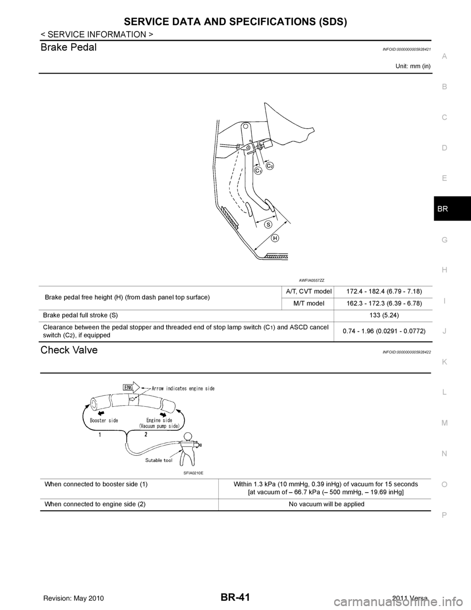
Brake pedal free height (H) (from dash panel top surface) A/T, CVT model 172.4 - 182.4 (6.79 - 7.18)
M/T model 162.3 - 172.3 (6.39 - 6.78)
Brake pedal full stroke (S) 133 (5.24)
Clearance between the pedal stopper and threaded end of stop lamp switch (C
1) and ASCD cancel
switch (C
2), if equipped 0.74 - 1.96 (0.0291 - 0.0772)
AWFIA0557ZZ
When connected to booster side (1)
Within 1.3 kPa (10 mmHg, 0.39 inHg) of vacuum for 15 seconds
[at vacuum of – 66.7 kPa (– 500 mmHg, – 19.69 inHg]
When connected to engine side (2) No vacuum will be applied
SFIA0210E
Revision: May 2010 2011 Versa
Page 889 of 3787
BR-42
< SERVICE INFORMATION >
SERVICE DATA AND SPECIFICATIONS (SDS)
Brake Booster
INFOID:0000000005928423
Front Disc BrakeINFOID:0000000005928424
Unit: mm (in)
Unit: mm (in)
Rear Drum BrakeINFOID:0000000005928425
Unit: mm (in)
Unit: mm (in)
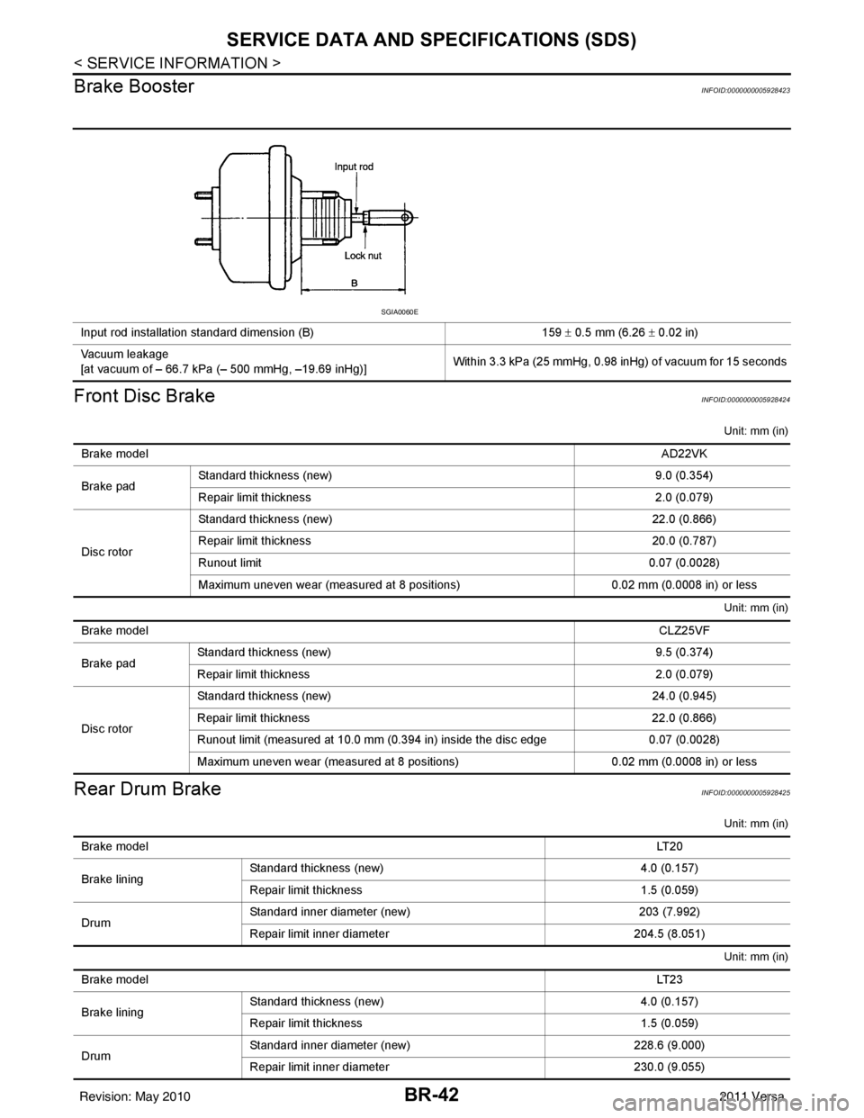
Input rod installation standard dimension (B) 159 ± 0.5 mm (6.26 ± 0.02 in)
Vacuum leakage
[at vacuum of – 66.7 kPa (– 500 mmHg, –19.69 inHg)] Within 3.3 kPa (25 mmHg, 0.98 inHg) of vacuum for 15 seconds
SGIA0060E
Brake model
AD22VK
Brake pad Standard thickness (new)
9.0 (0.354)
Repair limit thickness 2.0 (0.079)
Disc rotor Standard thickness (new)
22.0 (0.866)
Repair limit thickness 20.0 (0.787)
Runout limit 0.07 (0.0028)
Maximum uneven wear (measured at 8 positions) 0.02 mm (0.0008 in) or less
Brake model CLZ25VF
Brake pad Standard thickness (new)
9.5 (0.374)
Repair limit thickness 2.0 (0.079)
Disc rotor Standard thickness (new)
24.0 (0.945)
Repair limit thickness 22.0 (0.866)
Runout limit (measured at 10.0 mm (0.394 in) inside the disc edge 0.07 (0.0028)
Maximum uneven wear (measured at 8 positions) 0.02 mm (0.0008 in) or less
Brake model LT 2 0
Brake lining Standard thickness
(new) 4.0 (0.157)
Repair limit thickness 1.5 (0.059)
Drum Standard inner diameter (new)
203 (7.992)
Repair limit inner diameter 204.5 (8.051)
Brake model LT 2 3
Brake lining Standard thickness (new)
4.0 (0.157)
Repair limit thickness 1.5 (0.059)
Drum Standard inner diameter (new)
228.6 (9.000)
Repair limit inner diameter 230.0 (9.055)
Revision: May 2010 2011 Versa
Page 908 of 3787
![NISSAN TIIDA 2011 Service Repair Manual TROUBLE DIAGNOSISBRC-19
< SERVICE INFORMATION > [ABS]
C
D
E
G H
I
J
K L
M A
B
BRC
N
O P
Note 1: Confirm tire pressure is normal.
Note 2: ON/OFF timing of ABS warning lamp
ON: For approximately 2 secon](/manual-img/5/57396/w960_57396-907.png "NISSAN TIIDA 2011 Service Repair Manual TROUBLE DIAGNOSISBRC-19
< SERVICE INFORMATION > [ABS]
C
D
E
G H
I
J
K L
M A
B
BRC
N
O P
Note 1: Confirm tire pressure is normal.
Note 2: ON/OFF timing of ABS warning lamp
ON: For approximately 2 secon")
TROUBLE DIAGNOSISBRC-19
< SERVICE INFORMATION > [ABS]
C
D
E
G H
I
J
K L
M A
B
BRC
N
O P
Note 1: Confirm tire pressure is normal.
Note 2: ON/OFF timing of ABS warning lamp
ON: For approximately 2 seconds after ignition switch is turned ON, or when a malfunction is detected.
OFF: Approximately 2 seconds after ignition switch is turned ON (when system is in normal operation).
CONSULT-III Function (ABS)INFOID:0000000005928445
CONSULT-III can display each diagnostic item using the diagnostic test modes shown following.
Monitor item Display content Data monitor
Note: Error inspection
checklist
Condition Reference value in
normal operation
FR RH SENSOR
FR LH SENSOR
RR RH SENSOR
RR LH SENSOR Wheel speedVehicle stopped
0 [km/h (MPH)]
BRC-25, "
Wheel Sensor
System"Vehicle running (Note 1) Almost in accor-
dance with speed-
ometer display
(within
±10%)
BATTERY VOLT Battery voltage sup-
plied to ABS actuator
and electric unit (con-
trol unit)Ignition switch ON
10 to 16VBRC-28, "
ABS Control
Unit Power and Ground
Systems Inspection"
STOP LAMP SW
Stop lamp switch oper-
ationBrake pedal depressed ON
—
Brake pedal not depressed OFF
ABS WARN LAMP ABS warning lamp ON
condition (Note 2)ABS warning lamp ON ON
BRC-17, "
Basic Inspec-
tion"ABS warning lamp OFF OFF
MOTOR RELAY Operation status of mo-
tor and motor relayIgnition switch ON or running
(ABS not activated)
OFF
BRC-27, "
Actuator Motor,
Motor Relay, and Circuit
Inspection"Ignition switch ON or engine
running (ABS activated) ON
ACTUATOR RLY Actuator relay opera-
tion statusVehicle stopped (Ignition
switch ON)
OFF
BRC-27, "
Actuator Motor,
Motor Relay, and Circuit
Inspection"Vehicle stopped (Engine run-
ning) ON
FR LH IN SOL
FR LH OUT SOL
FR RH IN SOL
FR RH OUT SOL
RR RH IN SOL
RR RH OUT SOL
RR LH IN SOL
RR LH OUT SOL Solenoid valve opera-
tionActuator (solenoid) is active
(“ACTIVE TEST” with CON-
SULT-III) or actuator relay is in-
active (in fail-safe mode).
ON
BRC-26, "
Solenoid Valve
System Inspection"When actuator (solenoid) is not
active and actuator relay is ac-
tive (ignition switch ON). OFF
ABS SIGNAL
EBD SIGNAL Signal statusABS active
EBD active
ON
ABS system
EBD system
ABS not active
EBD not active OFF
ABS FAIL SIG
EBD FAIL SIG Fail signal statusABS fail
EBD fail
ON
ABS system
EBD system
ABS normal
EBD normal OFF
Diagnostic mode
Description
SELF DIAGNOSTIC RESULT Displays ABS actuator and electric unit (control unit) self-diagnosis results. DATA MONITOR Displays ABS actuator and electric unit (control unit) input/output data in real time.
CAN DIAG SUPPORT MNTR The result of transmit/receive diagnosis of CAN communication can be read. ACTIVE TEST Operation of electrical loads can be checked by sending drive signal to them.
Revision: May 2010 2011 Versa
Page 983 of 3787

CL-2
< SERVICE INFORMATION >
PRECAUTIONS
SERVICE INFORMATION
PRECAUTIONS
Precaution for Supplemental Restraint System (SRS) "AIR BAG" and "SEAT BELT
PRE-TENSIONER"
INFOID:0000000005928987
The Supplemental Restraint System such as “A IR BAG” and “SEAT BELT PRE-TENSIONER”, used along
with a front seat belt, helps to reduce the risk or severity of injury to the driver and front passenger for certain
types of collision. This system includes seat belt switch inputs and dual stage front air bag modules. The SRS
system uses the seat belt switches to determine the front air bag deployment, and may only deploy one front
air bag, depending on the severity of a collision and w hether the front occupants are belted or unbelted.
Information necessary to service the system safely is included in the SRS and SB section of this Service Man-
ual.
WARNING:
• To avoid rendering the SRS inopera tive, which could increase the risk of personal injury or death in
the event of a collision which would result in air bag inflation, all maintenance must be performed by
an authorized NISSAN/INFINITI dealer.
• Improper maintenance, including incorrect removal and installation of the SRS can lead to personal
injury caused by unintent ional activation of the system. For re moval of Spiral Cable and Air Bag
Module, see the SRS section.
• Do not use electrical test equipmen t on any circuit related to the SRS unless instructed to in this
Service Manual. SRS wiring harn esses can be identified by yellow and/or orange harnesses or har-
ness connectors.
PRECAUTIONS WHEN USING POWER TOOLS (AIR OR ELECTRIC) AND HAMMERS
WARNING:
• When working near the Airbag Diagnosis Sensor Unit or other Airbag System sensors with the Igni-
tion ON or engine running, DO NOT use air or electri c power tools or strike near the sensor(s) with a
hammer. Heavy vibration could activate the sensor( s) and deploy the air bag(s), possibly causing
serious injury.
• When using air or electric power tools or hammers , always switch the Ignition OFF, disconnect the
battery, and wait at least 3 minu tes before performing any service.
Precaution Necessary for Steering W heel Rotation After Battery Disconnect
INFOID:0000000005928988
NOTE:
• This Procedure is applied only to models with Intelligent Key system and NATS (NISSAN ANTI-THEFT SYS-
TEM).
• Remove and install all control units after disconnecting both battery cables with the ignition knob in the
″LOCK ″ position.
• Always use CONSULT-III to perform self-diagnosis as a part of each function inspection after finishing work.
If DTC is detected, perform trouble diagnosis according to self-diagnostic results.
For models equipped with the Intelligent Key system and NATS, an electrically controlled steering lock mech-
anism is adopted on the key cylinder.
For this reason, if the battery is disconnected or if the battery is discharged, the steering wheel will lock and
steering wheel rotation will become impossible.
If steering wheel rotation is required when battery pow er is interrupted, follow the procedure below before
starting the repair operation.
OPERATION PROCEDURE
1. Connect both battery cables. NOTE:
Supply power using jumper cables if battery is discharged.
2. Use the Intelligent Key or mechanical key to turn the ignition switch to the ″ACC ″ position. At this time, the
steering lock will be released.
3. Disconnect both battery cables. The steering lock will remain released and the steering wheel can be rotated.
4. Perform the necessary repair operation.
Revision: May 2010 2011 Versa
Page 990 of 3787
CLUTCH FLUIDCL-9
< SERVICE INFORMATION >
DE
F
G H
I
J
K L
M A
B
CL
N
O P
CLUTCH FLUID
Air Bleeding ProcedureINFOID:0000000005928996
CAUTION:
Do not spill clutch fluid onto painted surfaces. If it spills, wipe up immediately and wash the affected
area with water.
NOTE:
• Do not use a vacuum assist or any other type of power bleeder on this system. Use of a vacuum assist or power bleeder will not purge all the air from the system.
• Carefully monitor fluid level in reservoir tank during bleeding operation.
1. Fill master cylinder reservoir tank with new clutch fluid.
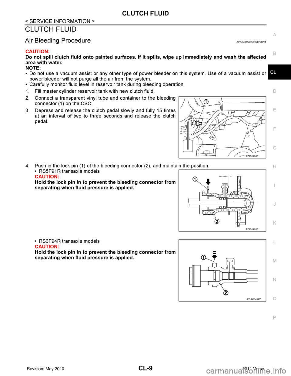
2. Connect a transparent vinyl tube and container to the bleeding connector (1) on the CSC.
3. Depress and release the clutch pedal slowly and fully 15 times at an interval of two to three seconds and release the clutch
pedal.
4. Push in the lock pin (1) of the bleeding connector (2), and maintain the position. • RS5F91R transaxle models
CAUTION:
Hold the lock pin in to preven t the bleeding connector from
separating when fluid pressure is applied.
• RS6F94R transaxle models
CAUTION:
Hold the lock pin in to preven t the bleeding connector from
separating when fluid pressure is applied.
PCIB1494E
PCIB1495E
JPDIB0041ZZ
Revision: May 2010 2011 Versa
Page 991 of 3787
CL-10
< SERVICE INFORMATION >
CLUTCH FLUID
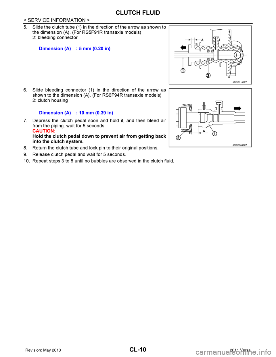
5. Slide the clutch tube (1) in the direction of the arrow as shown tothe dimension (A). (For RS5F91R transaxle models)
2: bleeding connector
6. Slide bleeding connector (1) in the direction of the arrow as shown to the dimension (A). (For RS6F94R transaxle models)
2: clutch housing
7. Depress the clutch pedal soon and hold it, and then bleed air from the piping. wait for 5 seconds.
CAUTION:
Hold the clutch pedal down to prevent air from getting back
into the clutch system.
8. Return the clutch tube and lock pin to their original positions.
9. Release clutch pedal and wait for 5 seconds.
10. Repeat steps 3 to 8 until no bubbles are observed in the clutch fluid. Dimension (A) : 5 mm (0.20 in)
JPDIB0147ZZ
Dimension (A) : 10 mm (0.39 in)
JPDIB0042ZZ
Revision: May 2010
2011 Versa
Page 998 of 3787
CLUTCH DISC, CLUTCH COVER AND FLYWHEELCL-17
< SERVICE INFORMATION >
DE
F
G H
I
J
K L
M A
B
CL
N
O P
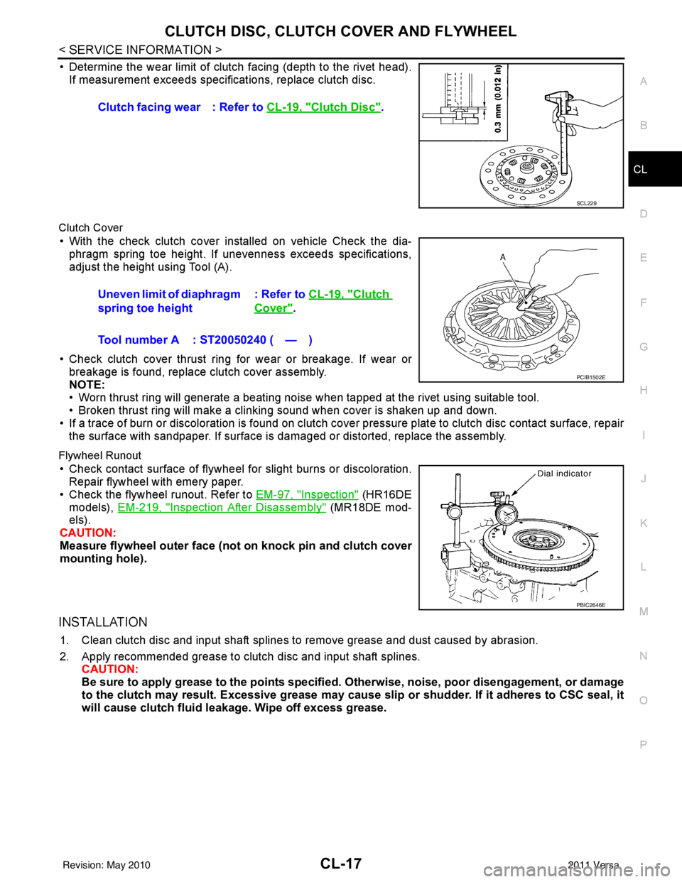
• Determine the wear limit of clutch facing (depth to the rivet head). If measurement exceeds specific ations, replace clutch disc.
Clutch Cover
• With the check clutch cover installed on vehicle Check the dia-
phragm spring toe height. If unevenness exceeds specifications,
adjust the height using Tool (A).
• Check clutch cover thrust ring for wear or breakage. If wear or breakage is found, replace clutch cover assembly.
NOTE:
• Worn thrust ring will generate a beating noise when tapped at the rivet using suitable tool.
• Broken thrust ring will make a clinking sound when cover is shaken up and down.
• If a trace of burn or discoloration is found on clutch cover pressure plate to clutch disc contact surface, repair the surface with sandpaper. If surface is damaged or distorted, replace the assembly.
Flywheel Runout
• Check contact surface of flywheel for slight burns or discoloration.Repair flywheel with emery paper.
• Check the flywheel runout. Refer to EM-97, "
Inspection" (HR16DE
models), EM-219, "
Inspection After Disassembly" (MR18DE mod-
els).
CAUTION:
Measure flywheel outer face (not on knock pin and clutch cover
mounting hole).
INSTALLATION
1. Clean clutch disc and input shaft splines to remove grease and dust caused by abrasion.
2. Apply recommended grease to clutch disc and input shaft splines. CAUTION:
Be sure to apply grease to the points specified. Otherwise, noise, poor disengagement, or damage
to the clutch may result. Excessive grease may cause sl ip or shudder. If it adheres to CSC seal, it
will cause clutch fluid l eakage. Wipe off excess grease.
Clutch facing wear : Refer to
CL-19, "
Clutch Disc".
SCL229
Uneven limit of diaphragm
spring toe height: Refer to CL-19, "Clutch
Cover".
Tool number A : ST20050240 ( — )
PCIB1502E
PBIC2646E
Revision: May 2010 2011 Versa