2011 NISSAN TIIDA Instrument Panel
[x] Cancel search: Instrument PanelPage 3372 of 3787
MTC-56
< SERVICE INFORMATION >
CONTROLLER
CONTROLLER
Removal and InstallationINFOID:0000000005930857
REMOVAL
1. Remove instrument finisher E. Refer to IP-11, "Component Parts" .
2. Remove instrument finisher D. Refer to IP-11, "
Component Parts" .
3. Remove cluster lid C. Refer to IP-11, "
Component Parts" .
4. Remove intake door lever knob. Refer to MTC-57, "
Disassembly and Assembly" .
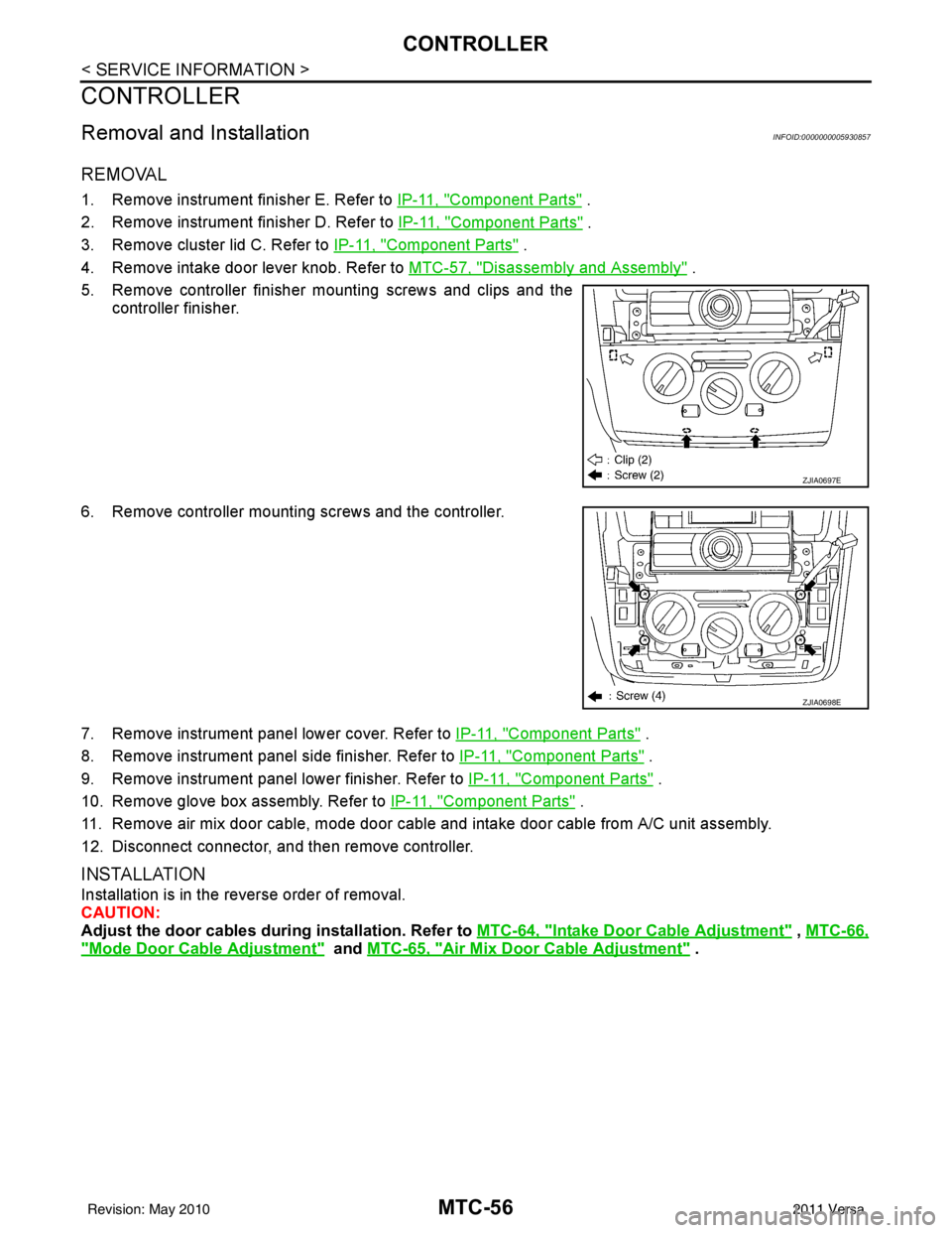
5. Remove controller finisher mounting screws and clips and the controller finisher.
6. Remove controller mounting screws and the controller.
7. Remove instrument panel lower cover. Refer to IP-11, "
Component Parts" .
8. Remove instrument panel side finisher. Refer to IP-11, "
Component Parts" .
9. Remove instrument panel lower finisher. Refer to IP-11, "
Component Parts" .
10. Remove glove box assembly. Refer to IP-11, "
Component Parts" .
11. Remove air mix door cable, mode door cable and intake door cable from A/C unit assembly.
12. Disconnect connector, and then remove controller.
INSTALLATION
Installation is in the reverse order of removal.
CAUTION:
Adjust the door cables duri ng installation. Refer to MTC-64, "
Intake Door Cable Adjustment" , MTC-66,
"Mode Door Cable Adjustment" and MTC-65, "Air Mix Door Cable Adjustment" .
ZJIA0697E
ZJIA0698E
Revision: May 2010 2011 Versa
Page 3376 of 3787
MTC-60
< SERVICE INFORMATION >
A/C UNIT ASSEMBLY
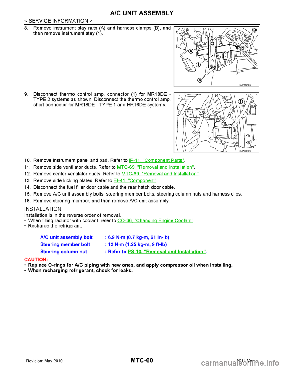
8. Remove instrument stay nuts (A) and harness clamps (B), andthen remove instrument stay (1).
9. Disconnect thermo control amp. connector (1) for MR18DE - TYPE 2 systems as shown. Di sconnect the thermo control amp.
short connector for MR18DE - TYPE 1 and HR16DE systems.
10. Remove instrument panel and pad. Refer to IP-11, "
Component Parts".
11. Remove side ventilator ducts. Refer to MTC-69, "
Removal and Installation".
12. Remove center ventilator ducts. Refer to MTC-69, "
Removal and Installation".
13. Remove side kicking plates. Refer to EI-41, "
Component".
14. Disconnect the fuel filler door cable and the rear hatch door cable.
15. Remove A/C unit assembly bolts, steering member bolts, steering column nuts and harness clips.
16. Remove steering member, and then remove A/C unit assembly.
INSTALLATION
Installation is in the reverse order of removal.
• When filling radiator with coolant, refer to CO-36, "
Changing Engine Coolant".
• Recharge the refrigerant.
CAUTION:
• Replace O-rings for A/C piping with new ones, and apply compressor oil when installing.
• When recharging refrigerant, check for leaks.
SJIA0646E
SJIA0647E
A/C unit assembly bolt : 6.9 N·m (0.7 kg-m, 61 in-lb)
Steering member bolt : 12 N·m (1.25 kg-m, 9 ft-lb)
Steering column nut : Refer to PS-10, "
Removal and Installation".
Revision: May 2010 2011 Versa
Page 3379 of 3787
BLOWER MOTORMTC-63
< SERVICE INFORMATION >
C
DE
F
G H
I
K L
M A
B
MTC
N
O P
BLOWER MOTOR
Removal and InstallationINFOID:0000000005930862
REMOVAL
1. Remove instrument panel and pad. Refer to IP-11, "Component Parts".
2. Remove side ventilator duct (right). Refer to MTC-69, "
Removal and Installation".
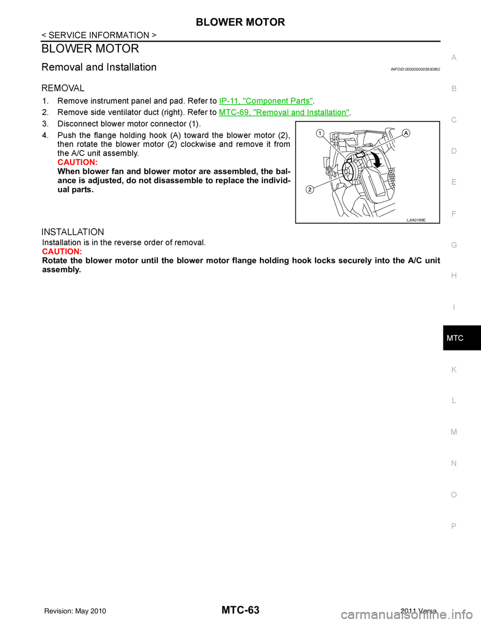
3. Disconnect blower motor connector (1).
4. Push the flange holding hook (A) toward the blower motor (2), then rotate the blower motor (2) clockwise and remove it from
the A/C unit assembly.
CAUTION:
When blower fan and blower motor are assembled, the bal-
ance is adjusted, do not di sassemble to replace the individ-
ual parts.
INSTALLATION
Installation is in the reverse order of removal.
CAUTION:
Rotate the blower motor until th e blower motor flange holding ho ok locks securely into the A/C unit
assembly.
LJIA0199E
Revision: May 2010 2011 Versa
Page 3385 of 3787
DUCTS AND GRILLESMTC-69
< SERVICE INFORMATION >
C
DE
F
G H
I
K L
M A
B
MTC
N
O P
DUCTS AND GRILLES
Removal and InstallationINFOID:0000000005930869
Floor Ducts - Canada Only
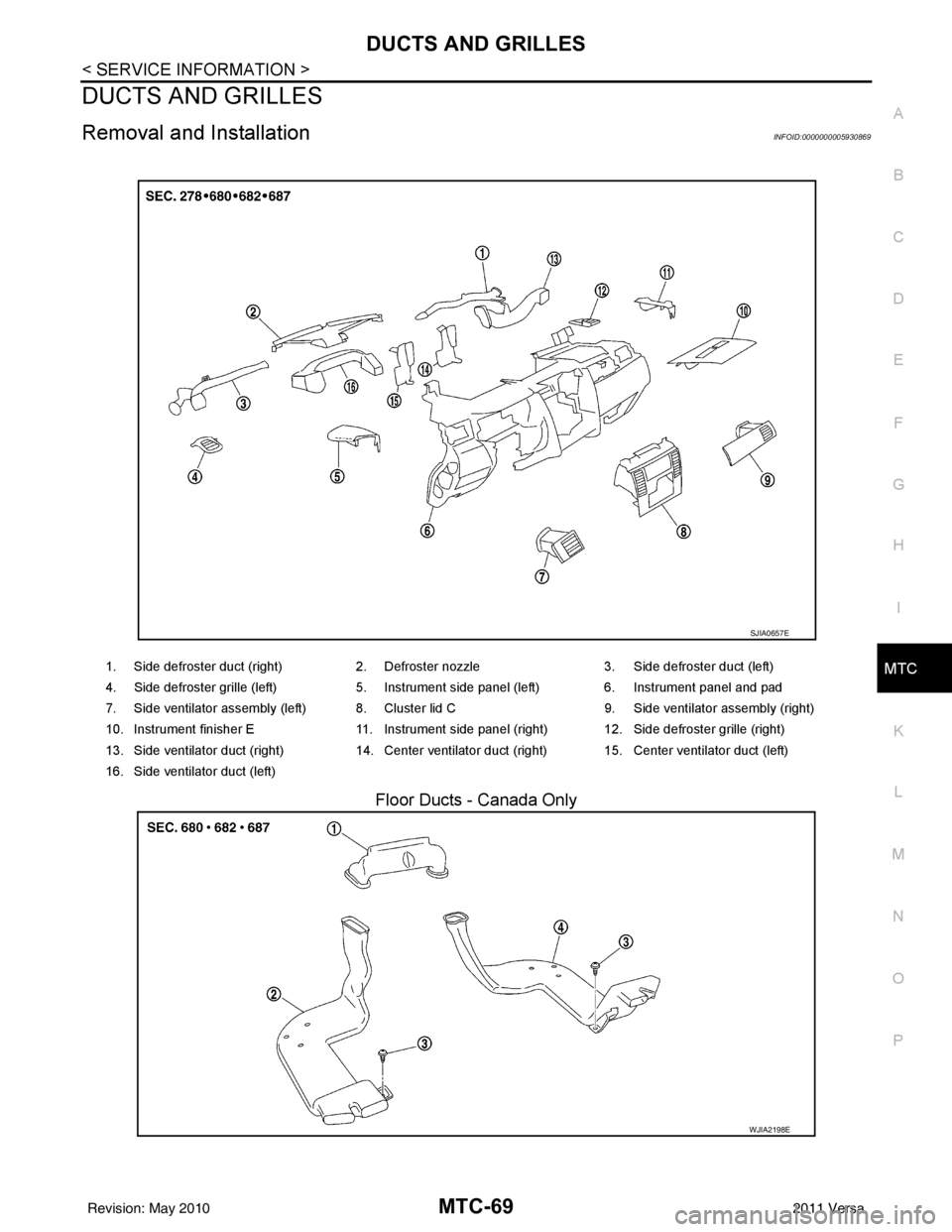
1. Side defroster duct (right) 2. Defroster nozzle3. Side defroster duct (left)
4. Side defroster grille (left) 5. Instrument side panel (left) 6. Instrument panel and pad
7. Side ventilator assembly (left) 8. Cluster lid C 9. Side ventilator assembly (right)
10. Instrument finisher E 11. Instrument side panel (right) 12. Side defroster grille (right)
13. Side ventilator duct (right) 14. Center ventilator duct (right) 15. Center ventilator duct (left)
16. Side ventilator duct (left)
SJIA0657E
WJIA2198E
Revision: May 2010 2011 Versa
Page 3387 of 3787
DUCTS AND GRILLESMTC-71
< SERVICE INFORMATION >
C
DE
F
G H
I
K L
M A
B
MTC
N
O P
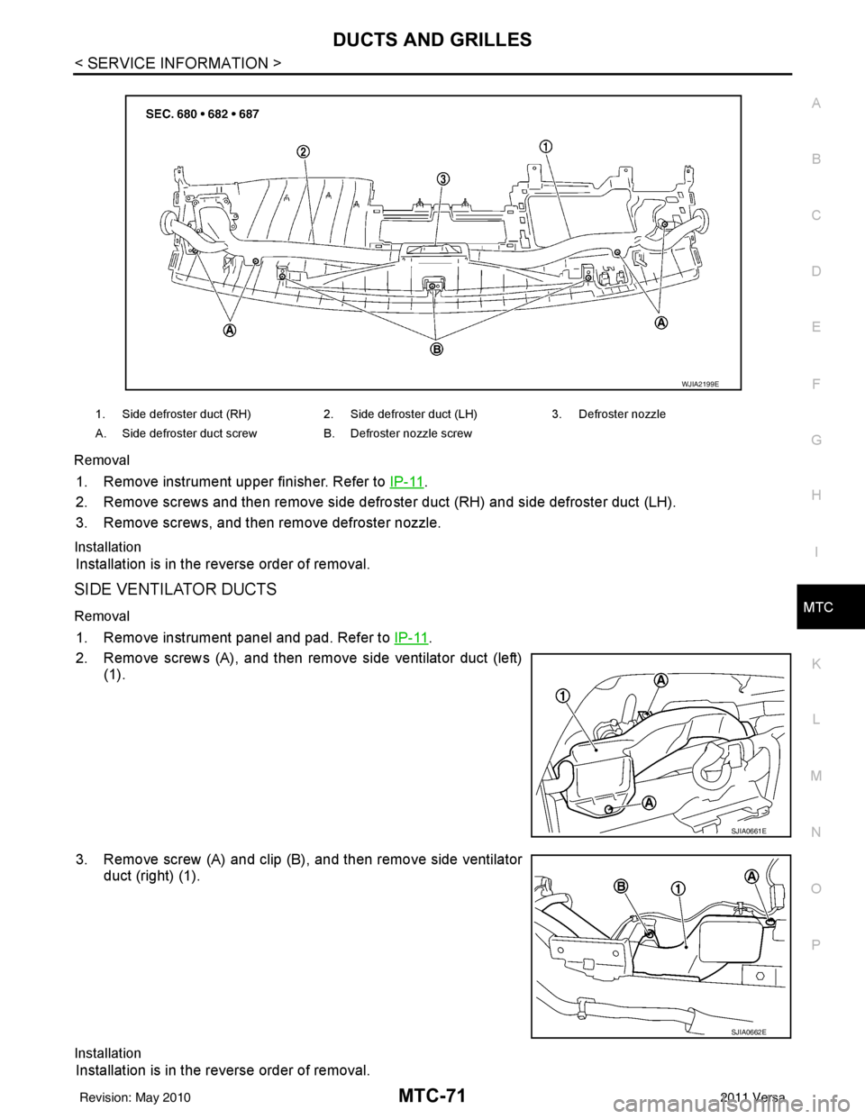
Removal
1. Remove instrument upper finisher. Refer to
IP-11.
2. Remove screws and then remove side defro ster duct (RH) and side defroster duct (LH).
3. Remove screws, and then remove defroster nozzle.
Installation
Installation is in the reverse order of removal.
SIDE VENTILATOR DUCTS
Removal
1. Remove instrument panel and pad. Refer to IP-11.
2. Remove screws (A), and then remove side ventilator duct (left) (1).
3. Remove screw (A) and clip (B), and then remove side ventilator duct (right) (1).
Installation
Installation is in the reverse order of removal.
1. Side defroster duct (RH) 2. Side defroster duct (LH)3. Defroster nozzle
A. Side defroster duct screw B. Defroster nozzle screw
WJIA2199E
SJIA0661E
SJIA0662E
Revision: May 2010 2011 Versa
Page 3388 of 3787
MTC-72
< SERVICE INFORMATION >
DUCTS AND GRILLES
CENTER VENTILATOR DUCTS
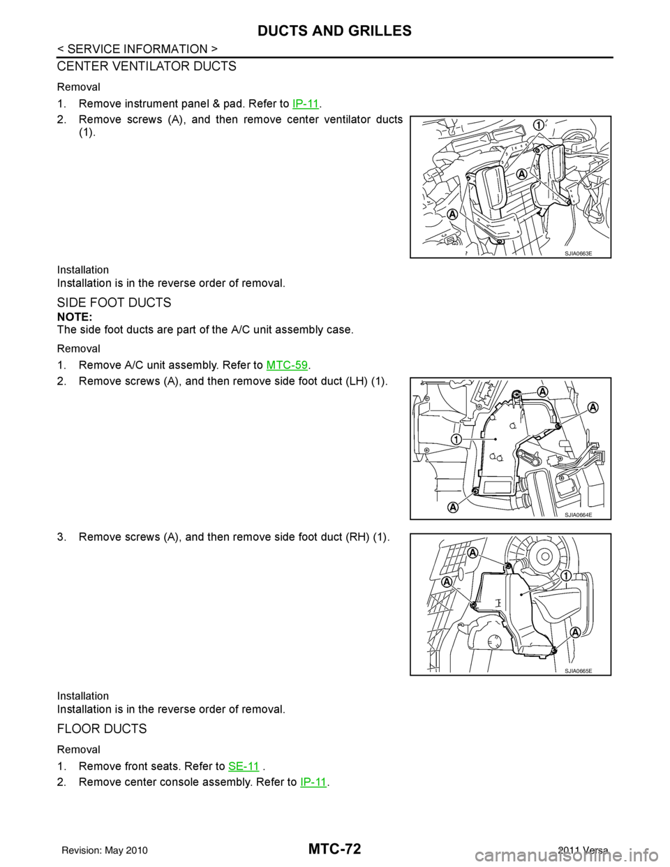
Removal
1. Remove instrument panel & pad. Refer to IP-11.
2. Remove screws (A), and then remove center ventilator ducts (1).
Installation
Installation is in the reverse order of removal.
SIDE FOOT DUCTS
NOTE:
The side foot ducts are part of the A/C unit assembly case.
Removal
1. Remove A/C unit assembly. Refer to MTC-59.
2. Remove screws (A), and then remove side foot duct (LH) (1).
3. Remove screws (A), and then remove side foot duct (RH) (1).
Installation
Installation is in the reverse order of removal.
FLOOR DUCTS
Removal
1. Remove front seats. Refer to SE-11 .
2. Remove center console assembly. Refer to IP-11
.
SJIA0663E
SJIA0664E
SJIA0665E
Revision: May 2010 2011 Versa
Page 3461 of 3787

HARNESSPG-41
< SERVICE INFORMATION >
C
DE
F
G H
I
J
L
M A
B
PG
N
O P
C2 M6 W/4 : Steering lock solenoid D2 M43 W/20 : Audio unit
B3 M7 W/16 : Door mirror re mote control switch D2 M44 W/16 : Audio unit
A3 M8 W/16 : To D2 D2 M45 W/12 : Audio unit
A3 M9 W/16 : To D1 A1 M46 BR/2 : Front tweeter LH
E2 M10 GR/2 : Instrument panel antenna G1 M47 BR/2 : Front tweeter RH
G3 M11 W/4 : To B106 B2 M48 L/4 : Heated mirror relay
G4 M12 W/16 : To B101 D3 M49 W/24 : iPod ® adapter
G3 M13 W/24 : To B102 E1 M50 GR/16 : iPod ® side
G3 M14 W/24 : To B120 E2 M52 W/40 : Intelligent key unit
B4 M15 W/16 : To B23 B2 M53 W/16 : EPS control unit
B4 M16 W/24 : To B24 B3 M54 B/2 : EPS control unit
D5 M17 B/1 : Parking brake switch D2 M55 W/4 : Hazard switch
F2 M18 W/40 : BCM (body control module) B2 M57 — : Body ground
F2 M19 W/15 : BCM (body control module) C1 M60 L/2 : EPS control unit
F3 M20 B/15 : BCM (body control module) F1 M61 — : Body ground
C2 M21 W/4 : NATS antenna amp. E2 M62 W/2 : Front blower motor
B3 M22 W/16 : Data link connector C1 M63 W/4 : Torque sensor
E3 M23 W/4 : Remote keyless entry receiver C3 M64 W/8 : Steering angle sensor
C1 M24 W/40 : Combination meter A2 M69 SMJ : To E7
C3 M25 /2 : Diode-1 D2 M70 W/24 : AV control unit
B2 M26 W/6 : Ignition switch D2 M71 W/9 : AV control unit
C2 M27 GR/6 : Key switch and key lock solenoid D1 M72 B/5 : USB interface and aux jack
C2 M28 W/16 : Combination switch B2 M73 GR/6 : Key switch and ignition knob switch
C3 M29 Y/6 : Combination switch G3 M74 W/12 : To D102
C3 M30 GR/8 : Combination switch G3 M75 W/12 : To D101
E3 M32 W/4 : To M150 E1 M76 B/4 : USB interface and aux jack
D2 M33 B/15 : Front air control F2 M77 Y/4 : Front passenger air bag module
B3 M34 GR/6 : VDC OFF switch A2 M78 B/2 : To E11
D4 M35 Y/28 : Air bag diagnosis sensor unit B1 M79 — : Body ground
C3 M36 W/3 : Front passenger air bag OFF indicator D3 M150 W/4 : To M32
D4 M38 W/6 : A/T shift selector (with A/T) C3 M151 W/4 : Front blower motor resistor
D4 M38 W/6 : CVT shift selector (without intelligent
key)
Revision: May 2010
2011 Versa
Page 3529 of 3787
RF-6
< SYMPTOM DIAGNOSIS >
SQUEAK AND RATTLE TROUBLE DIAGNOSES
If possible, drive the vehicle with the customer until the noise is duplicated. Note any additional information on
the Diagnostic Worksheet regarding the conditions or lo cation of the noise. This information can be used to
duplicate the same conditions when you confirm the repair.
If the noise can be duplicated easily during the test drive, to help identify the source of the noise, try to dupli-
cate the noise with the vehicle stopped by doing one or all of the following:
1) Close a door.
2) Tap or push/pull around the area where the noise appears to be coming from.
3) Rev the engine.
4) Use a floor jack to recreate vehicle “twist”.
5) At idle, apply engine load (electrical load, half-clutch on M/T model, drive position on CVT and A/T models).
6) Raise the vehicle on a hoist and hit a tire with a rubber hammer.
• Drive the vehicle and attempt to duplicate the conditions the customer states exist when the noise occurs.
• If it is difficult to duplicate the noise, drive the v ehicle slowly on an undulating or rough road to stress the
vehicle body.
CHECK RELATED SERVICE BULLETINS
After verifying the customer concern or symptom, chec k ASIST for Technical Service Bulletins (TSBs) related
to that concern or symptom.
If a TSB relates to the symptom, follo w the procedure to repair the noise.
LOCATE THE NOISE AND IDENTIFY THE ROOT CAUSE
1. Narrow down the noise to a general area. To help pi npoint the source of the noise, use a listening tool
(Engine Ear or mechanics stethoscope).
2. Narrow down the noise to a more specific area and identify the cause of the noise by:
• removing the components in the area that you suspect the noise is coming from.
Do not use too much force when removing clips and fasteners, otherwise clips and fastener can be broken
or lost during the repair, resulting in the creation of new noise.
• tapping or pushing/pulling the component that you suspect is causing the noise.
Do not tap or push/pull the component with excessive force, otherwise the noise will be eliminated only tem-
porarily.
• feeling for a vibration with your hand by touching the component(s) that you suspect is (are) causing the
noise.
• placing a piece of paper between components that you suspect are causing the noise.
• looking for loose components and contact marks. Refer to RF-7, "
Generic Squeak and Rattle Troubleshooting".
REPAIR THE CAUSE
• If the cause is a loose component, tighten the component securely.
• If the cause is insufficient clearance between components:
- separate components by repositioning or loos ening and retightening the component, if possible.
- insulate components with a suitable insulator such as urethane pads, foam blocks, felt cloth tape or urethane tape are available through your authorized Nissan Parts Department.
CAUTION:
Do not use excessive force as many components are constructed of plastic and may be damaged.
NOTE:
Always check with the Parts Departm ent for the latest parts information.
Each item can be ordered separately as needed.
URETHANE PADS [1.5 mm (0.059 in) thick]
Insulates connectors, harness, etc.
76268-9E005: 100 × 135 mm (3.94 × 5.31 in)/76884-71L01: 60 × 85 mm (2.36 × 3.35 in)/76884-71L02: 15 ×
25 mm (0.59 × 0.98 in)
INSULATOR (Foam blocks)
Insulates components from contact. Can be used to fill space behind a panel.
73982-9E000: 45 mm (1.77 in) thick, 50 × 50 mm (1.97 × 1.97 in)/73982-50Y00: 10 mm (0.39 in) thick, 50
× 50 mm (1.97 × 1.97 in)
INSULATOR (Light foam block)
80845-71L00: 30 mm (1.18 in) thick, 30 × 50 mm (1.18 × 1.97 in)
FELT CLOTH TAPE
Used to insulate where movement does not occu r. Ideal for instrument panel applications.
68370-4B000: 15 × 25 mm (0.59 × 0.98 in) pad/68239-13E00: 5 mm (0.20 in) wide tape roll
Revision: May 2010 2011 Versa