2011 NISSAN TIIDA Eco Switch
[x] Cancel search: Eco SwitchPage 2757 of 3787
PRECAUTIONSGW-3
< SERVICE INFORMATION >
C
DE
F
G H
J
K L
M A
B
GW
N
O P
SERVICE INFORMATION
PRECAUTIONS
Precaution for Supplemental Restraint System (SRS) "AIR BAG" and "SEAT BELT
PRE-TENSIONER"
INFOID:0000000005929457
The Supplemental Restraint System such as “AIR BAG” and “SEAT BELT PRE-TENSIONER”, used along
with a front seat belt, helps to reduce the risk or severi ty of injury to the driver and front passenger for certain
types of collision. This system includes seat belt switch inputs and dual stage front air bag modules. The SRS
system uses the seat belt switches to determine the front air bag deployment, and may only deploy one front
air bag, depending on the severity of a collision and w hether the front occupants are belted or unbelted.
Information necessary to service the system safely is included in the SRS and SB section of this Service Man-
ual.
WARNING:
• To avoid rendering the SRS inoper ative, which could increase the risk of personal injury or death in
the event of a collision which would result in air bag inflation, all maintenance must be performed by
an authorized NISSAN/INFINITI dealer.
• Improper maintenance, including in correct removal and installation of the SRS can lead to personal
injury caused by unintentional act ivation of the system. For removal of Spiral Cable and Air Bag
Module, see the SRS section.
• Do not use electrical test equipm ent on any circuit related to the SRS unless instructed to in this
Service Manual. SRS wiring harnesses can be identi fied by yellow and/or orange harnesses or har-
ness connectors.
PRECAUTIONS WHEN USING POWER TOOLS (AIR OR ELECTRIC) AND HAMMERS
WARNING:
• When working near the Airbag Diagnosis Sensor Un it or other Airbag System sensors with the Igni-
tion ON or engine running, DO NOT use air or el ectric power tools or strike near the sensor(s) with a
hammer. Heavy vibration could activate the sensor( s) and deploy the air bag(s), possibly causing
serious injury.
• When using air or electric power tools or hammers, always switch the Ignition OFF, disconnect the battery, and wait at least 3 minutes before performing any service.
Precaution Necessary for Steering Wheel Rotation After Battery Disconnect
INFOID:0000000005929458
NOTE:
• This Procedure is applied only to models with Intelligent Key system and NATS (NISSAN ANTI-THEFT SYS-
TEM).
• Remove and install all control units after disconnecti ng both battery cables with the ignition knob in the
″ LOCK ″ position.
• Always use CONSULT-III to perform self-diagnosis as a part of each function inspection after finishing work.
If DTC is detected, perform trouble diagnosis according to self-diagnostic results.
For models equipped with the Intelligent Key system and NATS , an electrically controlled steering lock mech-
anism is adopted on the key cylinder.
For this reason, if the battery is disconnected or if the battery is discharged, the steering wheel will lock and
steering wheel rotation will become impossible.
If steering wheel rotation is required when battery power is interrupted, follow the procedure below before
starting the repair operation.
OPERATION PROCEDURE
1. Connect both battery cables. NOTE:
Supply power using jumper cables if battery is discharged.
2. Use the Intelligent Key or mechanical key to turn the ignition switch to the ″ACC ″ position. At this time, the
steering lock will be released.
3. Disconnect both battery cables. The steering lock will remain released and the steering wheel can be
rotated.
4. Perform the necessary repair operation.
Revision: May 2010 2011 Versa
Page 2776 of 3787

GW-22
< SERVICE INFORMATION >
POWER WINDOW SYSTEM
Then, the motor raises the window until the switch is released.
WINDOW DOWN
When the main power window and door lock/unlock switch (rear LH) is pressed in the down position, power is
supplied
• through main power window and door lock/unlock switch terminal 3
• to rear power window switch LH terminal 3
• through rear power window switch LH terminal 4
• to rear power window motor LH terminal 1.
Ground is supplied
• through main power window and door lock/unlock switch terminal 1
• to rear power window switch LH terminal 2
• through rear power window switch LH terminal 5
• to rear power window motor LH terminal 2.
Then, the motor lowers the window until the switch is released.
When the main power window and door lock/unlock switch (rear RH) is pressed in the down position, power is
supplied
• through main power window and door lock/unlock switch terminal 5
• to rear power window switch RH terminal 3
• through rear power window switch RH terminal 4
• to rear power window motor RH terminal 1.
Ground is supplied
• through main power window and door lock/unlock switch terminal 7
• to rear power window switch RH terminal 2
• through rear power window switch RH terminal 5
• to rear power window motor RH terminal 2.
Then, the motor lowers the window until the switch is released.
AUTO OPERATION
The power window AUTO feature enables the driver to open the window without holding the window switch in
the down position.
POWER WINDOW LOCK
The power window lock is designed to lock operation of all windows except for front door window LH.
When in the lock position, the power window lock di sables power window and door lock/unlock switch RH and
rear power window switch LH and RH by disconnecting switch ground signal. This prevents the power window
motors from operating.
RETAINED POWER OPERATION
When the ignition switch is turned to the OFF position from ON or START position, power is supplied for 45
seconds
• through BCM terminal 68
• to main power window and door lock/unlock switch terminal 10
• to power window and door lock/unlock switch RH terminal 8 and
• to rear power window switches LH and RH terminal 1.
When power and ground are supplied, the BCM conti nues to be energized, and the power window can be
operated.
The retained power operation is canceled when the front LH or front RH door is opened.
Retained power operation period can be changed by CONSULT-III. Refer to GW-30, "
CONSULT-III Function
(BCM)" .
ANTI-PINCH SYSTEM
Main power window and door lock/unlock switch monitors the power window motor operation and the power
window position (full closed or other) for front LH power window by the signal from encoder in front power win-
dow motor LH.
When main power window and door lock/unlock switch detects interruption during the following close opera-
tions
• automatic close operation when igniti on switch is in the ON position
• automatic close operation during retained power operation
Main power window and door lock/unlock switch controls front power window motor LH for open and the
power window will be lowered.
Revision: May 2010 2011 Versa
Page 2783 of 3787
POWER WINDOW SYSTEMGW-29
< SERVICE INFORMATION >
C
DE
F
G H
J
K L
M A
B
GW
N
O P
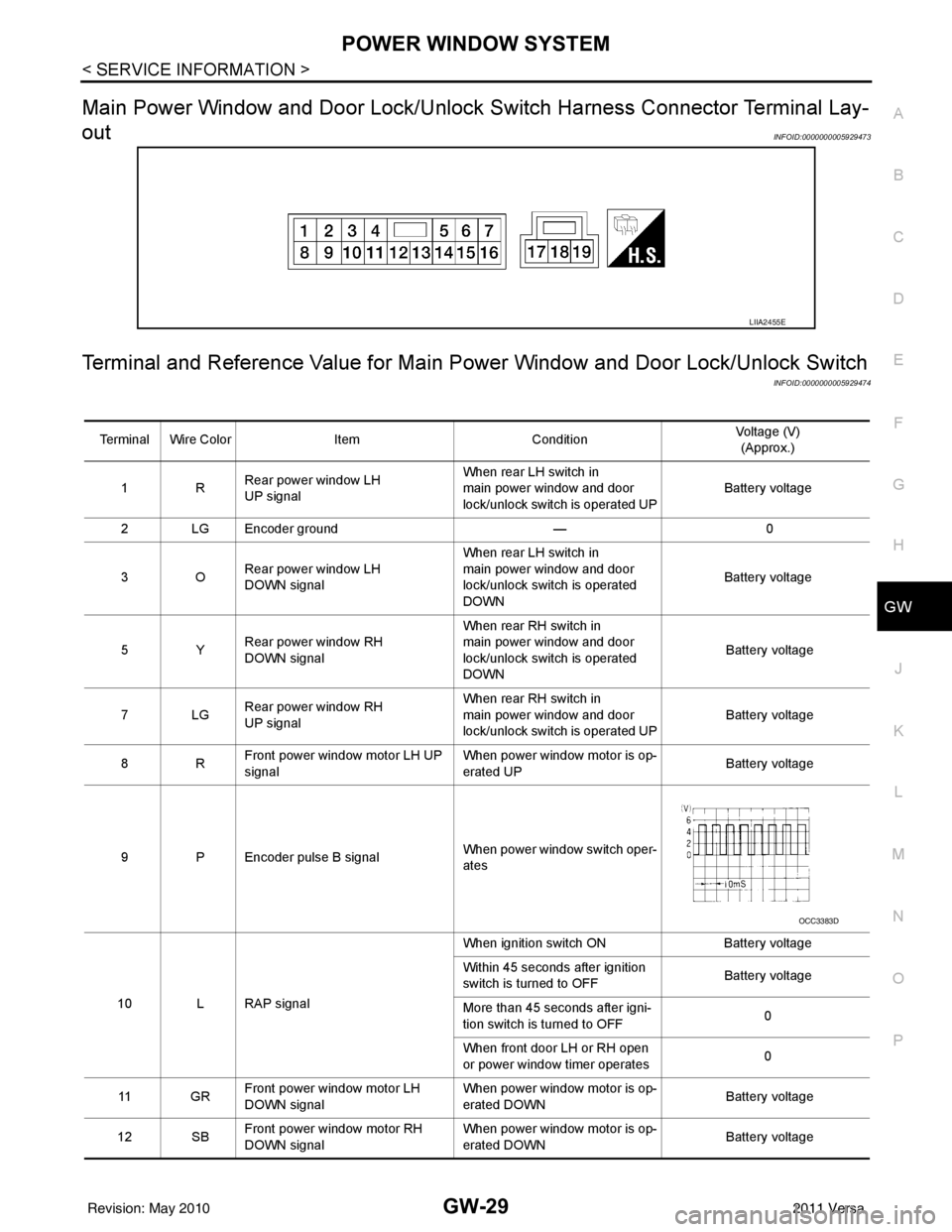
Main Power Window and Door Lock/Unlock Switch Harness Connector Terminal Lay-
out
INFOID:0000000005929473
Terminal and Reference Value for Main Po wer Window and Door Lock/Unlock Switch
INFOID:0000000005929474
LIIA2455E
Terminal Wire ColorItemCondition Voltage (V)
(Approx.)
1R Rear power window LH
UP signal When rear LH switch in
main power window and door
lock/unlock switch is operated UP
Battery voltage
2 LG Encoder ground — 0
3O Rear power window LH
DOWN signal When rear LH switch in
main power window and door
lock/unlock switch is operated
DOWN
Battery voltage
5Y Rear power window RH
DOWN signal When rear RH switch in
main power window and door
lock/unlock switch is operated
DOWN
Battery voltage
7LG Rear power window RH
UP signal When rear RH switch in
main power window and door
lock/unlock switch is operated UP
Battery voltage
8R Front power window motor LH UP
signal When power window motor is op-
erated UP
Battery voltage
9 P Encoder pulse B signal When power window switch oper-
ates
10 L RAP signal When ignition switch ON
Battery voltage
Within 45 seconds after ignition
switch is turned to OFF Battery voltage
More than 45 seconds after igni-
tion switch is turned to OFF 0
When front door LH or RH open
or power window timer operates 0
11 G R Front power window motor LH
DOWN signal When power window motor is op-
erated DOWN
Battery voltage
12 SB Front power window motor RH
DOWN signal When power window motor is op-
erated DOWN
Battery voltage
OCC3383D
Revision: May 2010
2011 Versa
Page 2785 of 3787
POWER WINDOW SYSTEMGW-31
< SERVICE INFORMATION >
C
DE
F
G H
J
K L
M A
B
GW
N
O P
WORK SUPPORT
DATA MONITOR
Power Window Auto Operation InitializationINFOID:0000000005929478
1. Turn the ignition switch ON.
2. Open the window—all the way DOWN.
3. Pull all the way UP on the switch and hold (close the window). • Continue holding the switch all the way UP for 4 seconds after the window is closed.
4. Confirm the window is now operating correctly. NOTE:
• If the window is still not operating correctly, refer to GW-31, "
Trouble Diagnosis Symptom Chart".
• The above initialization procedure must be performed if any of the following occur:
- Battery cable is disconnected
- Power window switch connector is disconnected
- Power window regulator is replaced
- Power window motor is replaced
- Window glass is removed
- Window glass run rubber is replaced
- Power window fuse is blown
- Window is partly opened and/or closed many times without being fully closed.
Trouble Diagnosis Symptom ChartINFOID:0000000005929479
Check that other systems us ing the signal of the following systems operate normally.
Test Item Description
RETAINED PWR This test is able to supply RAP signal (powe
r) from BCM (body control module) to power window
system and power sunroof system (if equipped). Those systems can be operated when turning on
“RETAINED PWR” on CONSULT-III screen even if the ignition switch is turned OFF.
NOTE:
During this test, CONSULT-III can be operated with ignition switch in OFF position. “RETAINED
PWR” should be turned “ON” or “OFF” on CONSULT-III screen when ignition switch is ON. Then
turn ignition switch OFF to check retained power operation. CONSULT-III might be stuck if “RE-
TAINED PWR” is turned “ON” or “OFF” on CONSULT-III screen when ignition switch is OFF.
Work item Description
RETAINED PWR RAP signal’s power supply period can be changed by mode setting. Selects RAP signal’s power
supply period between three steps
• MODE1 (45 sec.)/MODE2 (OFF)/MODE3 (2 min.).
Work item
Description
IGN ON SW Indicates (ON/OFF) condition of ignition switch
DOOR SW-DR Indicates (ON/OFF) condition of front door switch LH
DOOR SW-AS Indicates (ON/OFF) condition of front door switch RH
Symptom Repair orderRefer to page
None of the power windows can be operated using any switch 1. BCM power supply and ground circuit check
BCS-16
2. Main power window and door lock/unlock
power supply and ground circuit check GW-32
3. Replace main power window and door lock/
unlock switch
EI-36
Front power window LH alone does not operate 1. Front power window motor LH circuit check
GW-332. Replace main power window and door lock/
unlock switch EI-36
Revision: May 2010
2011 Versa
Page 2798 of 3787
GW-44
< SERVICE INFORMATION >
FRONT DOOR GLASS AND REGULATOR
FRONT DOOR GLASS AND REGULATOR
Removal and InstallationINFOID:0000000005929491
DOOR GLASS
Removal
1. Remove the front door finisher. Refer to EI-36, "Removal and Installation".
2. Disconnect the front door speaker electrical connector.
3. Position aside vapor barrier. NOTE:
If the vapor barrier is reused, cut the butyl-tape so that a part of butyl-tape remains on the vapor barrier.
4. Raise or lower the window until the glass bolts can be seen. • For power windows, temporarily reconnect the power window switch to operate the window.
• For manual windows, temporarily reinstall the window crankhandle to operate the window.
5. Remove the door glass bolts.
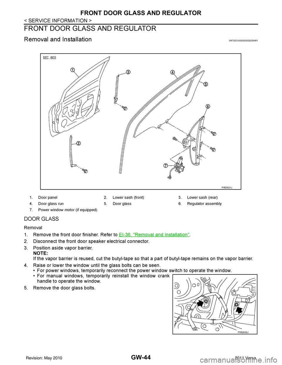
1. Door panel 2. Lower sash (front) 3. Lower sash (rear)
4. Door glass run 5. Door glass6. Regulator assembly
7. Power window motor (if equipped)
PIIB2631J
PIIB2632J
Revision: May 2010 2011 Versa
Page 2799 of 3787
FRONT DOOR GLASS AND REGULATORGW-45
< SERVICE INFORMATION >
C
DE
F
G H
J
K L
M A
B
GW
N
O P
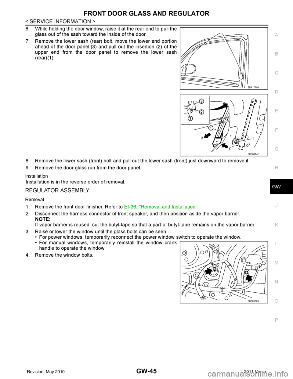
6. While holding the door window, raise it at the rear end to pull the glass out of the sash toward the inside of the door.
7. Remove the lower sash (rear) bolt, move the lower end portion ahead of the door panel.(3) and pull out the insertion (2) of the
upper end from the door panel to remove the lower sash
(rear)(1).
8. Remove the lower sash (front) bolt and pull out the lower sash (front) just downward to remove it.
9. Remove the door glass run from the door panel.
Installation
Installation is in the reverse order of removal.
REGULATOR ASSEMBLY
Removal
1. Remove the front door finisher. Refer to EI-36, "Removal and Installation".
2. Disconnect the harness connector of front speak er, and then position aside the vapor barrier.
NOTE:
If vapor barrier is reused, cut the butyl-tape so that a part of butyl-tape remains on the vapor barrier.
3. Raise or lower the window until the glass bolts can be seen. • For power windows, temporarily reconnect the power window switch to operate the window.
• For manual windows, temporarily reinstall the window crankhandle to operate the window.
4. Remove the window bolts.
SIIA1779J
PIIB6314E
PIIB2632J
Revision: May 2010 2011 Versa
Page 2801 of 3787
FRONT DOOR GLASS AND REGULATORGW-47
< SERVICE INFORMATION >
C
DE
F
G H
J
K L
M A
B
GW
N
O P
• Removal and installation of the door glass.
• Removal and installation of the door glass run.
Initialization
After installing each component to the vehicle, follow the steps below.
1. Disconnect the battery negative c able or disconnect power window switch's harness connector tempo-
rarily, then reconnect after at least 1 minute.
2. Turn ignition switch ON.
3. Open the window to its full width by operating the power window switch. (Exclude this procedure if the window is already fully opened).
4. Move the power window switch in the up direction (auto close position) and hold. Keep holding the switch
even when window is completely closed, and then release after 4 seconds have passed.
5. Confirm window is now operating correctly. NOTE:
Initialization may be cancelled with continuous opening and closing operation. In this case, initialize the
system.
INSPECT THE FUNCTION OF THE ANTI-PINCH SYSTEM
1. Fully open the door glass.
2. Place a wooden piece (wooden hammer handle, etc.) near the fully closed position.
3. Carry out fully closing operation with auto up switch.
• Check that the glass reverses without pinching the w ooden piece, is lowered approx.150 mm (5.91 in) or for
2 seconds and then stops.
• The glass should not be raised with power window main switch while it is reversing or lowering.
CAUTION:
• Use care to avoid being pinched during the inspection. Do not u se a hand, etc. in place of the
wooden piece durin g the inspection.
• Check that auto up function is normal before inspection, following the system initialization.
FITTING INSPECTION
• Make sure the glass is securely fit into the glass run groove.
• Lower the glass slightly [approx. 10 to 20 mm (0.39 to 0.79 in)] and make sure the clearance to the sash is
parallel. If the clearance between the glass and sash is not parallel, loosen the regulator bolts, guide rail
bolts, and the glass and guide rail bolts to correct the glass position.
• Make sure the system is normal with raising and lowering the glass.
Revision: May 2010 2011 Versa
Page 2803 of 3787
REAR DOOR GLASS AND REGULATORGW-49
< SERVICE INFORMATION >
C
DE
F
G H
J
K L
M A
B
GW
N
O P
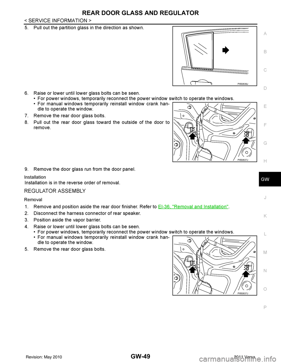
5. Pull out the partition glass in the direction as shown.
6. Raise or lower until lower glass bolts can be seen. • For power windows, temporarily reconnect the power window switch to operate the windows.
• For manual windows temporarily reinstall window crank han- dle to operate the window.
7. Remove the rear door glass bolts.
8. Pull out the rear door glass toward the outside of the door to remove.
9. Remove the door glass run from the door panel.
Installation
Installation is in the reverse order of removal.
REGULATOR ASSEMBLY
Removal
1. Remove and position aside the rear door finisher. Refer to EI-36, "Removal and Installation".
2. Disconnect the harness connector of rear speaker.
3. Position aside the vapor barrier.
4. Raise or lower until lower glass bolts can be seen. • For power windows, temporarily reconnect the power window switch to operate the windows.
• For manual windows temporarily reinstall window crank han- dle to operate the window.
5. Remove the rear door glass bolts.
PIIB2636J
PIIB2637J
PIIB2637J
Revision: May 2010 2011 Versa