2011 NISSAN TIIDA door
[x] Cancel search: doorPage 519 of 3787

SQUEAK AND RATTLE TROUBLE DIAGNOSESBL-9
< SERVICE INFORMATION >
C
DE
F
G H
J
K L
M A
B
BL
N
O P
SILICONE GREASE
Used instead of UHMW tape that will be visible or not fit.
Note: Will only last a few months.
SILICONE SPRAY
Use when grease cannot be applied.
DUCT TAPE
Use to eliminate movement.
CONFIRM THE REPAIR
Confirm that the cause of a noise is repaired by test driving the vehicle. Operate the vehicle under the same
conditions as when the noise originally occurred. Refer to the notes on the Diagnostic Worksheet.
Generic Squeak and Rattle TroubleshootingINFOID:0000000005929274
Refer to Table of Contents for specific component removal and installation information.
INSTRUMENT PANEL
Most incidents are caused by contact and movement between:
1. The cluster lid A and instrument panel
2. Acrylic lens and combination meter housing
3. Instrument panel to front pillar garnish
4. Instrument panel to windshield
5. Instrument panel mounting pins
6. Wiring harnesses behind the combination meter
7. A/C defroster duct and duct joint
These incidents can usually be located by tapping or moving the components to duplicate the noise or by
pressing on the components while driving to stop the noi se. Most of these incidents can be repaired by apply-
ing felt cloth tape or silicone spray (in hard to reach areas). Urethane pads can be used to insulate wiring har-
ness.
CAUTION:
Do not use silicone spray to isolate a squeak or ra ttle. If you saturate the area with silicone, you will
not be able to recheck the repair.
CENTER CONSOLE
Components to pay attention to include:
1. Shift selector cover to finisher
2. A/C control unit and cluster lid C
3. Wiring harnesses behind audio and A/C control unit
The instrument panel repair and isolation pr ocedures also apply to the center console.
DOORS
Pay attention to the:
1. Finisher and inner panel making a slapping noise
2. Inside handle escutcheon to door finisher
3. Wiring harnesses tapping
4. Door striker out of alignment causing a popping noise on starts and stops
Tapping or moving the components or pressing on them while driving to duplicate the conditions can isolate
many of these incidents. You can usually insulate the ar eas with felt cloth tape or insulator foam blocks from
the NISSAN Squeak and Rattle Kit (J-43980) to repair the noise.
TRUNK
Trunk noises are often caused by a loose jack or loose items put into the trunk by the owner.
In addition look for:
1. Trunk lid bumpers out of adjustment
2. Trunk lid striker out of adjustment
3. The trunk lid torsion bars knocking together
4. A loose license plate or bracket
Revision: May 2010 2011 Versa
Page 532 of 3787
BL-22
< SERVICE INFORMATION >
POWER DOOR LOCK SYSTEM
POWER DOOR LOCK SYSTEM
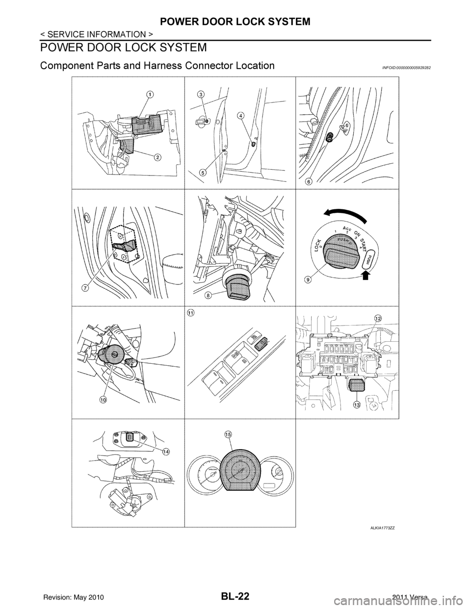
Component Parts and Harness Connector LocationINFOID:0000000005929282
ALKIA1773ZZ
Revision: May 2010 2011 Versa
Page 533 of 3787

POWER DOOR LOCK SYSTEMBL-23
< SERVICE INFORMATION >
C
DE
F
G H
J
K L
M A
B
BL
N
O P
System DescriptionINFOID:0000000005929283
Power is supplied at all times
• through 40A fusible link (letter g, located in the fuse and fusible link box)
• to BCM terminal 70
• through 10A fuse [No. 8, located in the fuse block (J/B)]
• to BCM terminal 57
• through 10A fuse [No. 14, located in the fuse block (J/B)]
• to key switch terminal 2 (without Intelligent Key system)
• through 10A fuse [No. 31, located in the fuse block (J/B)]
• to key switch and ignition knob switch terminals 2 and 4 (with Intelligent Key system).
When key switch is ON (key is inserted in ignition key cylinder), power is supplied
• through key switch terminal 1 (without Intelligent Key system) or key switch and ignition knob terminal 1 (with Intelligent Key system)
• to BCM terminal 37.
Ground is supplied
• to BCM terminal 67
• through body grounds M57 and M61.
LOCK OPERATION
When the door is locked with main power window and door lock/unlock switch, ground is supplied
• to BCM terminal 45
• through main power window and door lock and unlock switch terminals 17 and 18
• through body grounds M57 and M61.
When the door is locked with power window and door lock/unlock switch RH, ground is supplied
• to BCM terminal 45
• through power window and door lock and unlock switch RH terminals 1 and 3
• through body grounds M57 and M61.
When the door is locked with front door lock assemb ly LH (key cylinder switch), ground is supplied
• to BCM terminal 8
• through front door lock assembly LH (key cylinder switch) terminals 4 and 6
• through body grounds M57 and M61.
UNLOCK OPERATION
When the door is unlocked with main power window and door lock/unlock switch, ground is supplied
• to BCM terminal 46
• through main power window and door lock/unlock switch terminals 6 and 17
• through body grounds M57 and M61.
When the door is unlocked with power window and door lock/unlock switch RH, ground is supplied
• to BCM terminal 46
• through power window and door lock and unlock switch RH terminals 2 and 3
• through body grounds M57 and M61.
When the door is unlocked with front door lock assemb ly LH (key cylinder switch), ground is supplied
• to BCM terminal 7
• through front door lock assembly LH (key cylinder switch) terminals 4 and 5
1. BCM M18, M19, M20
(view with glove box removed) 2. Intelligent Key unit M52
(if equipped) 3. Front door lock assembly LH (key cyl-
inder switch) D14
4. Front door switch LH B8, RH B108 5. Front door lock assembly LH (actuator) D14
Front door lock assembly RH (actuator)
D1146. Rear door switch LH B6, RH B116
7. Rear door lock actuator LH D205 RH D305 8. Key switch and ignition knob switch M73
(with A/T or CVT and Intelligent Key) 9. Key switch and ignition knob switch
M73 (with M/T and Intelligent Key)
10. Key switch and key lock solenoid M27 (without Intelligent key) 11. Main power window and door lock/un-
lock switch D7, D8
Power window and door lock/unlock
switch RH D105 12. Fuse block (with Intelligent Key)
(view with instrument panel LH re-
moved)
13. Passenger select unlock relay M2 (with Intelligent Key) 14. Back door lock assembly (back door
switch) D405 (hatchback view with back
door open) 15. Combination meter M24
Revision: May 2010
2011 Versa
Page 534 of 3787

BL-24
< SERVICE INFORMATION >
POWER DOOR LOCK SYSTEM
• through body grounds M57 and M61.
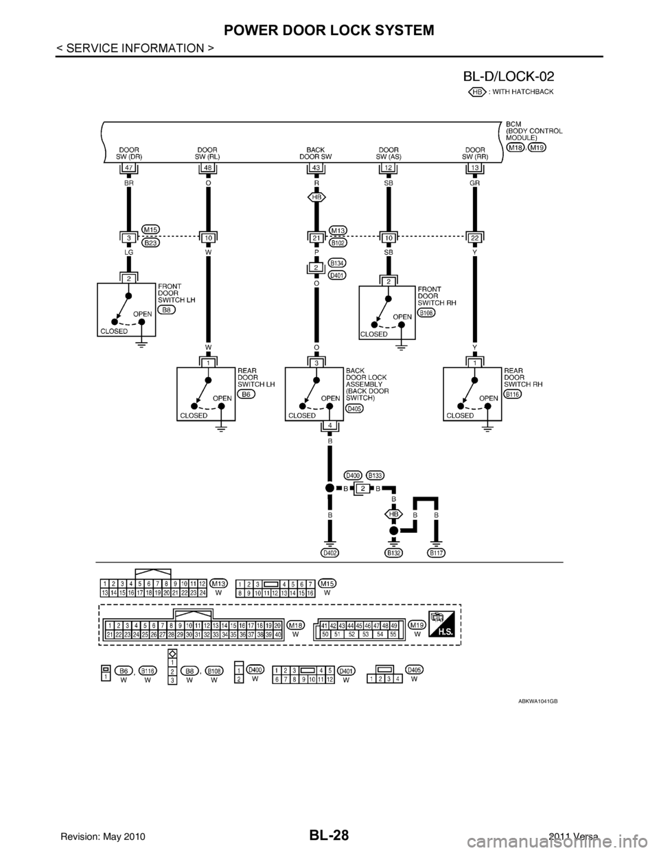
When the front door switch LH is ON (door is OPEN), ground is supplied
• to BCM terminal 47
• through front door switch LH terminal 2
• through front door switch LH case ground.
When the front door switch RH is ON (door is OPEN), ground is supplied
• to BCM terminal 12
• through front door switch RH terminal 2
• through front door switch RH case ground.
When the rear door switch LH is ON (door is OPEN), ground is supplied
• to BCM terminal 48
• through rear door switch LH terminal 1
• through rear door switch LH case ground.
When the rear door switch RH is ON (door is OPEN), ground is supplied
• to BCM terminal 13
• through rear door switch RH terminal 1
• through rear door switch RH case ground.
When the back door lock assembly (back door switch) ( hatchback) is ON (back door is OPEN), ground is sup-
plied
• to BCM terminal 43
• through back door lock assembly (back door switch) terminals 3 and 4
• through body grounds B117, B132 and D402.
OUTLINE
Functions available by operating the inside door lock and unlock switches
• Interlocked with the locking operation of door lock and unlock switch, door lock actuators of all doors are
locked.
• Interlocked with the unlocking operation of door lock and unlock switch, door lock actuators of all doors are
unlocked.
Functions available by operating the front door lock assembly LH (key cylinder switch)
• Interlocked with the locking operation of front door lock assembly LH (key cylinder switch), door lock actua-
tors of all doors are locked.
• When front door lock assembly LH (key cylinder switch) is unlocked, front door lock assembly LH (actuator)
is unlocked.
• When front door lock assembly LH (key cylinder swit ch) is unlocked for the second time within 5 seconds
after the first operation, front door lock assembly RH (actuator), rear door lock actuator LH and rear door
lock actuator RH are unlocked.
Key reminder door system
When door lock and unlock switch is operated to lock doors with ignition key inserted in key cylinder and any
door open, all door lock actuators are locked and then unlocked.
AUTOMATIC DOOR LOCKS (LOCK OPERATION)
The interlock door lock function is the function that locks all doors linked with the vehicle speed.
Vehicle Speed Sensing Auto Door Lock*1
All doors are locked when the vehicle speed reaches 24 km/h (15 MPH) or more.
BCM outputs the lock signal to all door lock actuators when it detects that the ignition switch is turned ON, all
doors are closed and the vehicle speed received from the combination meter via CAN communication
becomes 15 MPH (24 km/h) or more.
If a door is opened and closed at any time during one ignition cycle (OFF → ON), even after initial auto door
lock has taken place, the BCM will relock all doors when the vehicle speed reaches 15 MPH (24 km/h) or more
again.
Setting change of Automatic Door Locks (LOCK) Function
The lock operation setting of the autom atic door locks function can be changed.
With CONSULT-III
The ON/OFF switching of the automatic door locks (LOC K) function and the type selection of the automatic
door locks (LOCK) function can be performed at the WO RK SUPPORT setting of CONSULT-III. Refer to BL-
41, "CONSULT-III Function (BCM)".
Without CONSULT- III
The automatic door locks (LOCK) function can be swit ched ON/OFF by performing the following operation.
Revision: May 2010 2011 Versa
Page 535 of 3787
POWER DOOR LOCK SYSTEMBL-25
< SERVICE INFORMATION >
C
DE
F
G H
J
K L
M A
B
BL
N
O P
1. Close all doors (door switch OFF).
2. Turn ignition switch ON.
3. Within 20 seconds of turning the ignition switch ON, press and hold the door lock and unlock switch to the LOCK position for more than 5 seconds.
4. The switching is completed when the hazard lamps blink.
5. The ignition switch must be turned OFF and ON again between each setting change.
AUTOMATIC DOOR LOCKS (UNLOCK OPERATION)
The automatic door locks (UNLOCK) function is the function that unlocks all doors linked with the key position.
IGN OFF Interlock Door Unlock*1
For vehicles equipped with Intelligent Key system, all doors are unlocked when the power supply position is
changed from ON to OFF.
For vehicles not equipped with Intelligent Key system , all doors are unlocked when the mechanical key is
removed from the ignition key cylinder.
BCM outputs the unlock signal to all door lock actuator s when it detects that the power supply position is
changed from ignition switch ON to OFF (with Intelligent Key) or when the mechanical key is removed from the
ignition key cylinder (without Intelligent Key).
Setting change of Automatic Door Locks (UNLOCK) Function
The lock operation setting of the aut omatic door locks function can be changed.
With CONSULT-III
The ON/OFF switching of the automatic door locks (UNL OCK) function and the type selection of the automatic
door locks (UNLOCK) function can be performed at the WORK SUPPORT setting of CONSULT-III. Refer to
BL-41, "
CONSULT-III Function (BCM)".
Without CONSULT- III
The automatic door locks (UNLOCK) function can be sw itched ON/OFF by performing the following operation.
1. Close all doors (door switch OFF).
2. Turn ignition switch ON.
3. Within 20 seconds of turning the ignition switch ON, press and hold the door lock and unlock switch to the UNLOCK position for more than 5 seconds.
4. The switching is completed when the hazard lamps blink.
5. The ignition switch must be turned OFF and ON again between each setting change.
*1: This function is set to ON before delivery.
CAN Communication System DescriptionINFOID:0000000005929284
Refer to LAN-7 .
OFF → ON : 2 blinks
ON → OFF : 1 blink
OFF → ON : 2 blinks
ON → OFF : 1 blink
Revision: May 2010 2011 Versa
Page 536 of 3787
BL-26
< SERVICE INFORMATION >
POWER DOOR LOCK SYSTEM
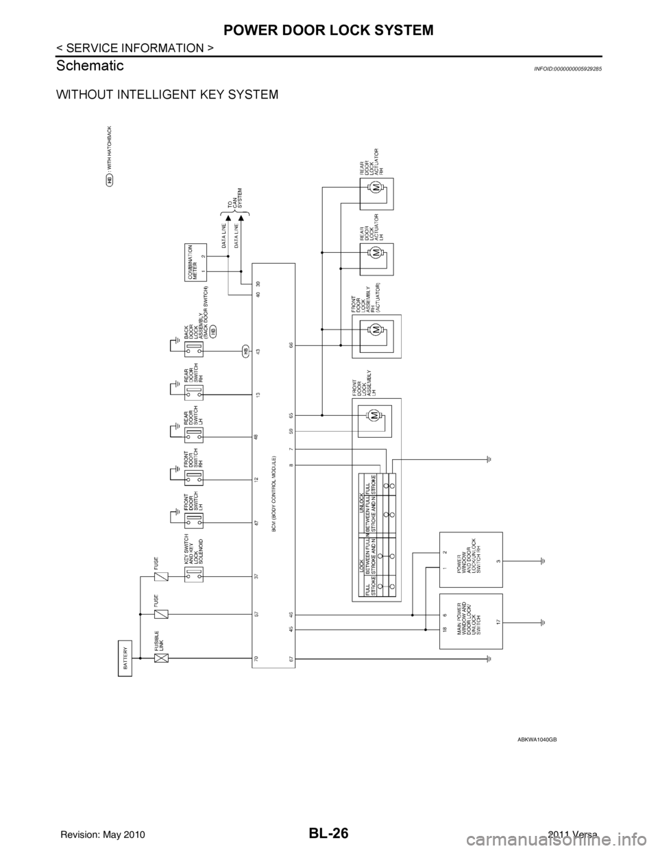
Schematic
INFOID:0000000005929285
WITHOUT INTELLIGENT KEY SYSTEM
ABKWA1040GB
Revision: May 2010 2011 Versa
Page 537 of 3787
POWER DOOR LOCK SYSTEMBL-27
< SERVICE INFORMATION >
C
DE
F
G H
J
K L
M A
B
BL
N
O P
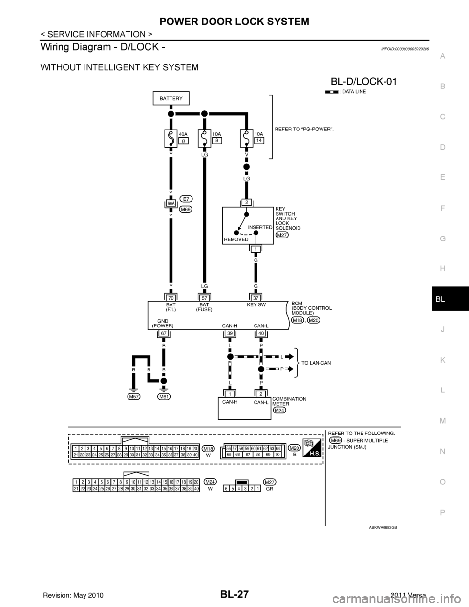
Wiring Diagram - D/LOCK -INFOID:0000000005929286
WITHOUT INTELLIGENT KEY SYSTEM
ABKWA0683GB
Revision: May 2010 2011 Versa
Page 538 of 3787
BL-28
< SERVICE INFORMATION >
POWER DOOR LOCK SYSTEM
ABKWA1041GB
Revision: May 20102011 Versa