2011 NISSAN TIIDA oil pressure
[x] Cancel search: oil pressurePage 276 of 3787
DISASSEMBLYAT-259
< SERVICE INFORMATION >
DE
F
G H
I
J
K L
M A
B
AT
N
O P
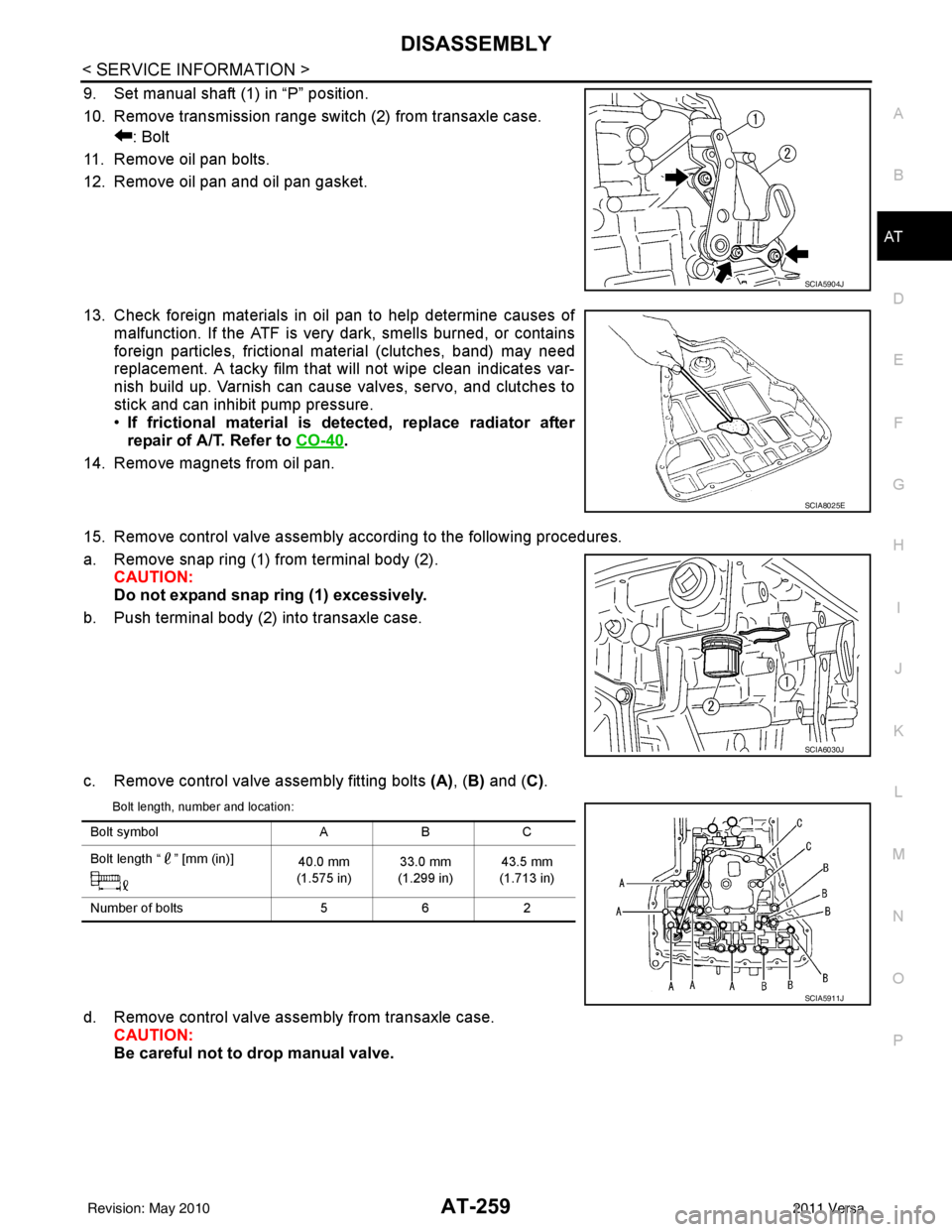
9. Set manual shaft (1) in “P” position.
10. Remove transmission range switch (2) from transaxle case. : Bolt
11. Remove oil pan bolts.
12. Remove oil pan and oil pan gasket.
13. Check foreign materials in oil pan to help determine causes of malfunction. If the ATF is very dark, smells burned, or contains
foreign particles, frictional material (clutches, band) may need
replacement. A tacky film that will not wipe clean indicates var-
nish build up. Varnish can cause valves, servo, and clutches to
stick and can inhibit pump pressure.
•If frictional material is detected, replace radiator after
repair of A/T. Refer to CO-40
.
14. Remove magnets from oil pan.
15. Remove control valve assembly according to the following procedures.
a. Remove snap ring (1) from terminal body (2). CAUTION:
Do not expand snap ring (1) excessively.
b. Push terminal body (2) into transaxle case.
c. Remove control valve assembly fitting bolts (A), (B) and ( C).
Bolt length, number and location:
d. Remove control valve assembly from transaxle case.
CAUTION:
Be careful not to drop manual valve.
SCIA5904J
SCIA8025E
SCIA6030J
Bolt symbol ABC
Bolt length “ ” [mm (in)] 40.0 mm
(1.575 in) 33.0 mm
(1.299 in) 43.5 mm
(1.713 in)
Number of bolts 562
SCIA5911J
Revision: May 2010 2011 Versa
Page 299 of 3787
AT-282
< SERVICE INFORMATION >
REPAIR FOR COMPONENT PARTS
DISASSEMBLY
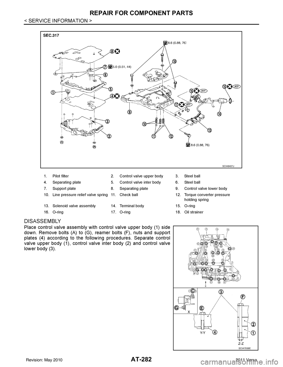
Place control valve assembly with control valve upper body (1) side
down. Remove bolts (A) to (G), reamer bolts (F), nuts and support
plates (4) according to the following procedures. Separate control
valve upper body (1), control valve inter body (2) and control valve
lower body (3).
1. Pilot filter2. Control valve upper body 3. Steel ball
4. Separating plate 5. Control valve inter body 6. Steel ball
7. Support plate 8. Separating plate9. Control valve lower body
10. Line pressure relief valve spring 11. Check ball 12. Torque converter pressure
holding spring
13. Solenoid valve assembly 14. Terminal body 15. O-ring
16. O-ring 17. O-ring18. Oil strainer
SCIA8407J
SCIA7058E
Revision: May 2010 2011 Versa
Page 303 of 3787
AT-286
< SERVICE INFORMATION >
REPAIR FOR COMPONENT PARTS
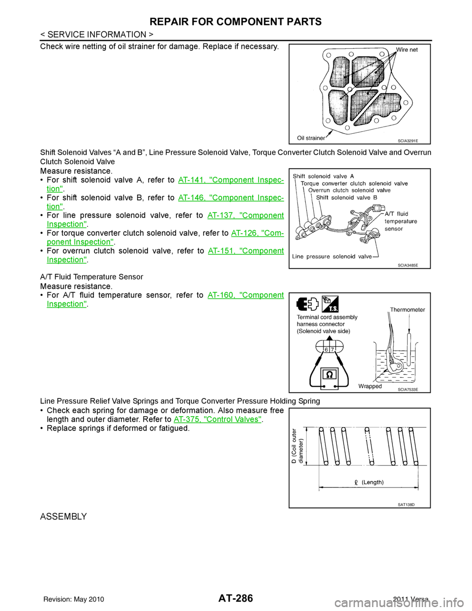
Check wire netting of oil strainer for damage. Replace if necessary.
Shift Solenoid Valves “A and B”, Line Pressure Solenoid Valve, Torque Converter Clutch Solenoid Valve and Overrun
Clutch Solenoid Valve
Measure resistance.
• For shift solenoid valve A, refer to AT-141, "
Component Inspec-
tion".
• For shift solenoid valve B, refer to AT-146, "
Component Inspec-
tion".
• For line pressure solenoid valve, refer to AT-137, "
Component
Inspection".
• For torque converter clutch solenoid valve, refer to AT-126, "
Com-
ponent Inspection".
• For overrun clutch solenoid valve, refer to AT-151, "
Component
Inspection".
A/T Fluid Temperature Sensor
Measure resistance.
• For A/T fluid temperature sensor, refer to AT-160, "
Component
Inspection".
Line Pressure Relief Valve Springs and Torque Converter Pressure Holding Spring
• Check each spring for damage or deformation. Also measure free
length and outer diameter. Refer to AT-375, "
Control Valves".
• Replace springs if deformed or fatigued.
ASSEMBLY
SCIA3291E
SCIA3485E
SCIA7533E
SAT138D
Revision: May 2010 2011 Versa
Page 332 of 3787
REPAIR FOR COMPONENT PARTSAT-315
< SERVICE INFORMATION >
DE
F
G H
I
J
K L
M A
B
AT
N
O P
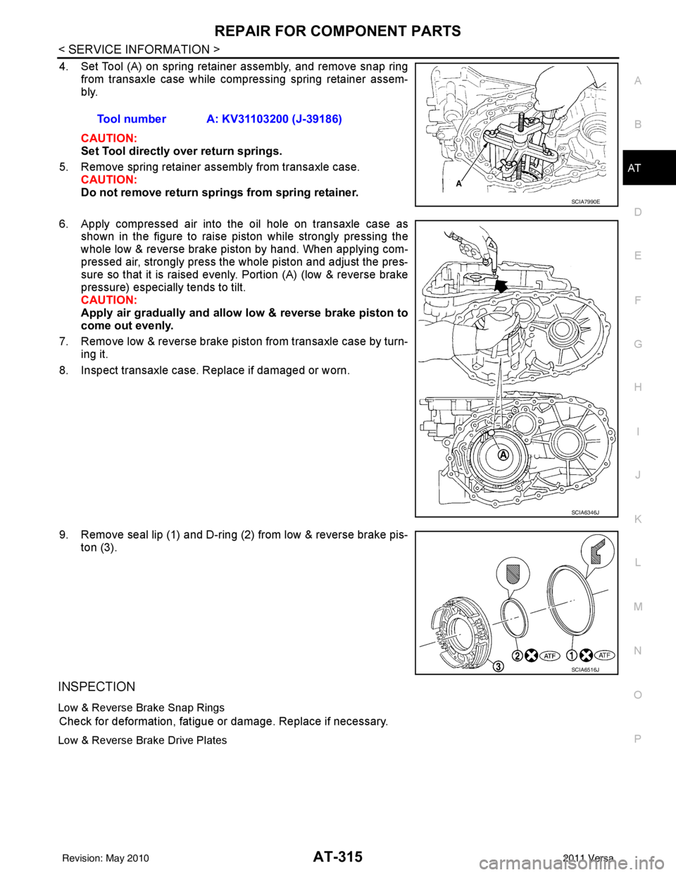
4. Set Tool (A) on spring retainer assembly, and remove snap ring from transaxle case while compressing spring retainer assem-
bly.
CAUTION:
Set Tool directly over return springs.
5. Remove spring retainer assembly from transaxle case. CAUTION:
Do not remove return springs from spring retainer.
6. Apply compressed air into the oil hole on transaxle case as shown in the figure to raise piston while strongly pressing the
whole low & reverse brake piston by hand. When applying com-
pressed air, strongly press the whole piston and adjust the pres-
sure so that it is raised evenly. Portion (A) (low & reverse brake
pressure) especially tends to tilt.
CAUTION:
Apply air gradually and allow low & reverse brake piston to
come out evenly.
7. Remove low & reverse brake piston from transaxle case by turn- ing it.
8. Inspect transaxle case. Replace if damaged or worn.
9. Remove seal lip (1) and D-ring (2) from low & reverse brake pis- ton (3).
INSPECTION
Low & Reverse Brake Snap Rings
Check for deformation, fatigue or damage. Replace if necessary.
Low & Reverse Brake Drive Plates
Tool number A: KV31103200 (J-39186)
SCIA7990E
SCIA6346J
SCIA6516J
Revision: May 2010 2011 Versa
Page 508 of 3787

BCS-18
< SERVICE INFORMATION >
BCM (BODY CONTROL MODULE)
WORK SUPPORT
Display Item List
CAN Communication Inspection Using CONSULT-III (Self-Diagnosis)INFOID:0000000005929262
1.SELF-DIAGNOSTIC RESULT CHECK
1. Connect CONSULT–III and select “BCM” on “SELECT SYSTEM” screen.
2. Select “BCM” on “SELECT TEST ITEM” screen, and select “SELF-DIAG RESULTS”.
3. Check display content in self-diagnostic results.
System and item CONSULT-III
display Diagnostic test mode (Inspection by part)
WORK
SUPPORT SELF
DIAGNOS- TIC RE-
SULT CAN DIAG
SUPPORT MNTR DATA
MONITOR ECU
IDENTI- FICA-
TION AC-
TIVE
TEST CON-
FIGU-
RATION
BCM BCM×× × × ×
Power door lock sys-
tem DOOR LOCK
×× ×
Rear defogger REAR DEFOG-
GER ××
Warning chime BUZZER ××
Room lamp timer INT LAMP ×× ×
Remote keyless entry
system MULTI REMOTE
ENT
××
×
Headlamp HEAD LAMP×× ×
Wiper WIPER×× ×
Turn signal lamp
Hazard lamp FLASHER
××
Blower fan switch sig-
nal
Air conditioner switch
signal AIR CONDITION-
ER
××
Intelligent Key INTELLIGENT
KEY ×
Combination switch COMB SW ×
NVIS (NATS) IMMU ××
Interior lamp battery
saver BATTERY SAV-
ER
××
×
Back door/Trunk TRUNK ××
Theft alarm THEFT ALARM×× ×
Retained accessory
power control RETAINED PWR
×× ×
Oil pressure swit ch SIGNAL BUFFER ××
Low tire pressure moni-
tor AIR PRESSURE
MONITOR
××
× ×
Panic alarm PANIC ALARM ×
ItemDescription
RESET SETTING VALUE Return a value set with WORK SUPPORT of each system to a default value in factory shipment.
Revision: May 2010 2011 Versa
Page 932 of 3787
![NISSAN TIIDA 2011 Service Repair Manual SYSTEM DESCRIPTIONBRC-43
< SERVICE INFORMATION > [VDC/TCS/ABS]
C
D
E
G H
I
J
K L
M A
B
BRC
N
O P
TCS FunctionINFOID:0000000005928470
• Spinning of the drive wheels is detected by the ABS/TCS/VDC con](/manual-img/5/57396/w960_57396-931.png "NISSAN TIIDA 2011 Service Repair Manual SYSTEM DESCRIPTIONBRC-43
< SERVICE INFORMATION > [VDC/TCS/ABS]
C
D
E
G H
I
J
K L
M A
B
BRC
N
O P
TCS FunctionINFOID:0000000005928470
• Spinning of the drive wheels is detected by the ABS/TCS/VDC con")
SYSTEM DESCRIPTIONBRC-43
< SERVICE INFORMATION > [VDC/TCS/ABS]
C
D
E
G H
I
J
K L
M A
B
BRC
N
O P
TCS FunctionINFOID:0000000005928470
• Spinning of the drive wheels is detected by the ABS/TCS/VDC control unit using inputs from the wheel speed sensors. If wheel spin occurs, the drive wheel right and left brake fluid pressure control and engine
fuel cut are conducted while the throttle value is restricted to reduce the engine torque and decrease the
amount of wheel spin. In addition, the throttle openi ng is controlled to achieve the optimum engine torque.
• Depending on road condition, the vehicle may have a sluggi sh feel. This is normal, because optimum trac-
tion has the highest priority during TCS operation.
• TCS may be activated during sudden vehicle acceleration, wide open throttle acceleration, sudden transmis- sion shifts or when the vehicle is driven on a road with a varying surface friction coefficient.
• The SLIP indicator lamp flashes to inform the driver of TCS operation.
VDC FunctionINFOID:0000000005928471
• In addition to the ABS/TCS function, the driver steering amount and brake operation amount are detected
from the steering angle sensor, and the vehicle's driving status (amount of under steering/over steering) is
determined using inputs from the yaw rate/side/decel G sensor, wheel speed sensors, etc. and this informa-
tion is used to improve vehicle stability by controlling the braking and engine torque application to the
wheels.
• The SLIP indicator lamp flashes to inform the driver of VDC operation.
• During VDC operation, the vehicle body and brake pedal may vibrate lightly and a mechanical noise may be
heard. This is normal.
• The ABS warning lamp, VDC OFF indicator lamp and SLIP indicator lamp may turn on when the vehicle is
subject to strong shaking or large vibration, such as when the vehicle is on a turn table or a ship while the
engine is running or steep slope. In this case, restart the engine on a normal road and if the ABS warning
lamp, VDC OFF indicator lamp and SLIP indicator lamp turn off, there is no problem.
Wheel SensorsINFOID:0000000005928472
The front sensor units consist of a gear-shaped sensor rotor and a
sensor element. The element contains a magnet around which a coil
is wound. The front wheel sensors are installed on the front of the
wheel knuckles. As the wheel rotates, the sensor generates a
square-wave signal. The frequency increases as the wheel speed
increases.
The rear sensor units consist of wheel hubs with a series of internal
magnets and a sensor element. The rear wheel sensors are installed
on the inner side of the wheel knuckles. As the wheel rotates, the
sensor generates a square-wave signal. The frequency increases as
the wheel speed increases.
Fail-Safe FunctionINFOID:0000000005928473
ABS/EBD SYSTEM
In case of an electrical malfunction with the ABS, the ABS warning lamp, VDC OFF indicator lamp and SLIP
indicator lamp will turn on. In case of an electrical malfunction with the EBD system, the BRAKE warning lamp,
ABS warning lamp, VDC OFF indicator lamp and SLIP indicator lamp will turn on.
LBR333
WFIA0033E
Revision: May 2010 2011 Versa
Page 986 of 3787

NOISE, VIBRATION AND HARSHNESS (NVH) TROUBLESHOOTINGCL-5
< SERVICE INFORMATION >
DE
F
G H
I
J
K L
M A
B
CL
N
O P
NOISE, VIBRATION AND HARSHN ESS (NVH) TROUBLESHOOTING
NVH Troubleshooting ChartINFOID:0000000005928993
Use the chart below to help you find the cause of the symptom. The numbers indicate the order of the inspec-
tion. If necessary, repair or replace these parts.
Reference pageCL-6CL-9EM-197CL-13CL-16EM-219
SUSPECTED PARTS (Possible cause)
CLUTCH PEDAL (Inspection and adjustment)
CLUTCH LINE (Air in line)
ENGINE MOUNTING (Loose)
CSC (Concentric slave cylinder) (Worn, dirty or damaged)
CLUTCH DISC (Out of true)
CLUTCH DISC (Runou t is excessive)
CLUTCH DISC (Lining broken)
CLUTCH DISC (Dirty or burned)
CLUTCH DISC (Oily)
CLUTCH DISC (Worn out)
CLUTCH DISC (Hardened)
CLUTCH DISC (Lack of spline grease)
DIAPHRAGM SPRING (Damaged)
DIAPHRAGM SPRING (Out of tip alignment)
PRESSURE PLATE (Distortion)
FLYWHEEL (Distortion)
Symptom Clutch grabs/chatters
122 2 2 2
Clutch pedal spongy 1
Clutch noisy 1
Clutch slips 1 2 23 4 5
Clutch does not disengage 12 55555 5667
Revision: May 2010 2011 Versa
Page 997 of 3787
CL-16
< SERVICE INFORMATION >
CLUTCH DISC, CLUTCH COVER AND FLYWHEEL
CLUTCH DISC, CLUTCH COVER AND FLYWHEEL
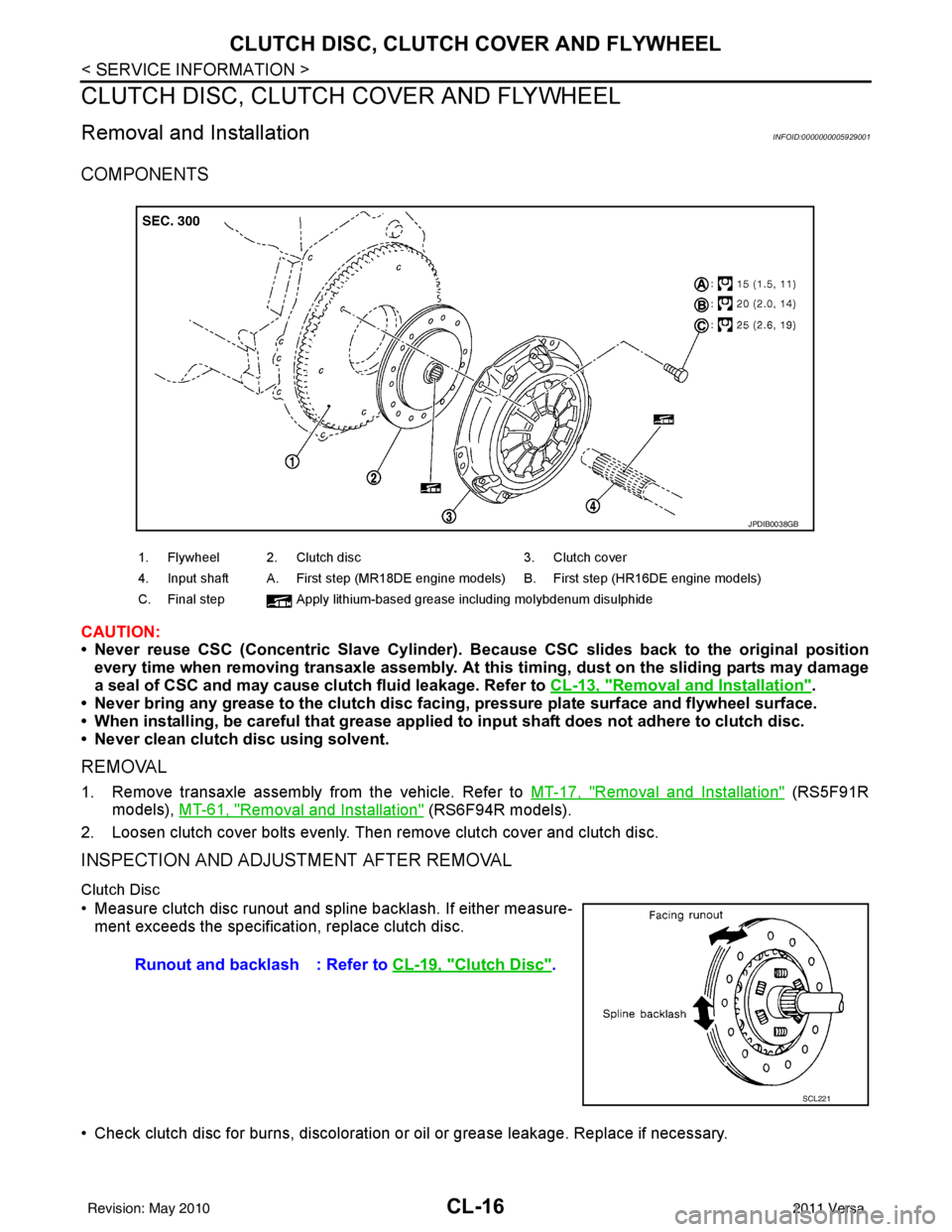
Removal and InstallationINFOID:0000000005929001
COMPONENTS
CAUTION:
• Never reuse CSC (Concentric Slave Cylinder). Because CSC slides back to the original position
every time when removing transaxle assembly. At this timing, dust on the sliding parts may damage
a seal of CSC and may cause clutch fluid leakage. Refer to CL-13, "
Removal and Installation".
• Never bring any grease to the clutch disc faci ng, pressure plate surface and flywheel surface.
• When installing, be careful that grease applied to input shaft does not adhere to clutch disc.
• Never clean clutch disc using solvent.
REMOVAL
1. Remove transaxle assembly from the vehicle. Refer to MT-17, "Removal and Installation" (RS5F91R
models), MT-61, "
Removal and Installation" (RS6F94R models).
2. Loosen clutch cover bolts evenly. Then remove clutch cover and clutch disc.
INSPECTION AND ADJUSTMENT AFTER REMOVAL
Clutch Disc
• Measure clutch disc runout and spline backlash. If either measure- ment exceeds the specificat ion, replace clutch disc.
• Check clutch disc for burns, discoloration or oil or grease leakage. Replace if necessary.
1. Flywheel 2. Clutch disc 3. Clutch cover
4. Input shaft A. First step (MR18DE engine models) B. First step (HR16DE engine models)
C. Final step Apply lithium-based grease including molybdenum disulphide
JPDIB0038GB
Runout and backlash : Refer to CL-19, "Clutch Disc".
SCL221
Revision: May 2010 2011 Versa