Page 154 of 3787
P0745 PRESSURE CONTROL SOLENOID AAT-137
< SERVICE INFORMATION >
DE
F
G H
I
J
K L
M A
B
AT
N
O P
NG >> GO TO 6.
6.CHECK TCM
1. Check TCM input/output signal. Refer to AT-75, "
TCM Terminal and Reference Value" .
2. If NG, recheck TCM pin terminals for dam age or loose connection with harness connector.
OK or NG
OK >> INSPECTION END
NG >> Repair or replace damaged parts.
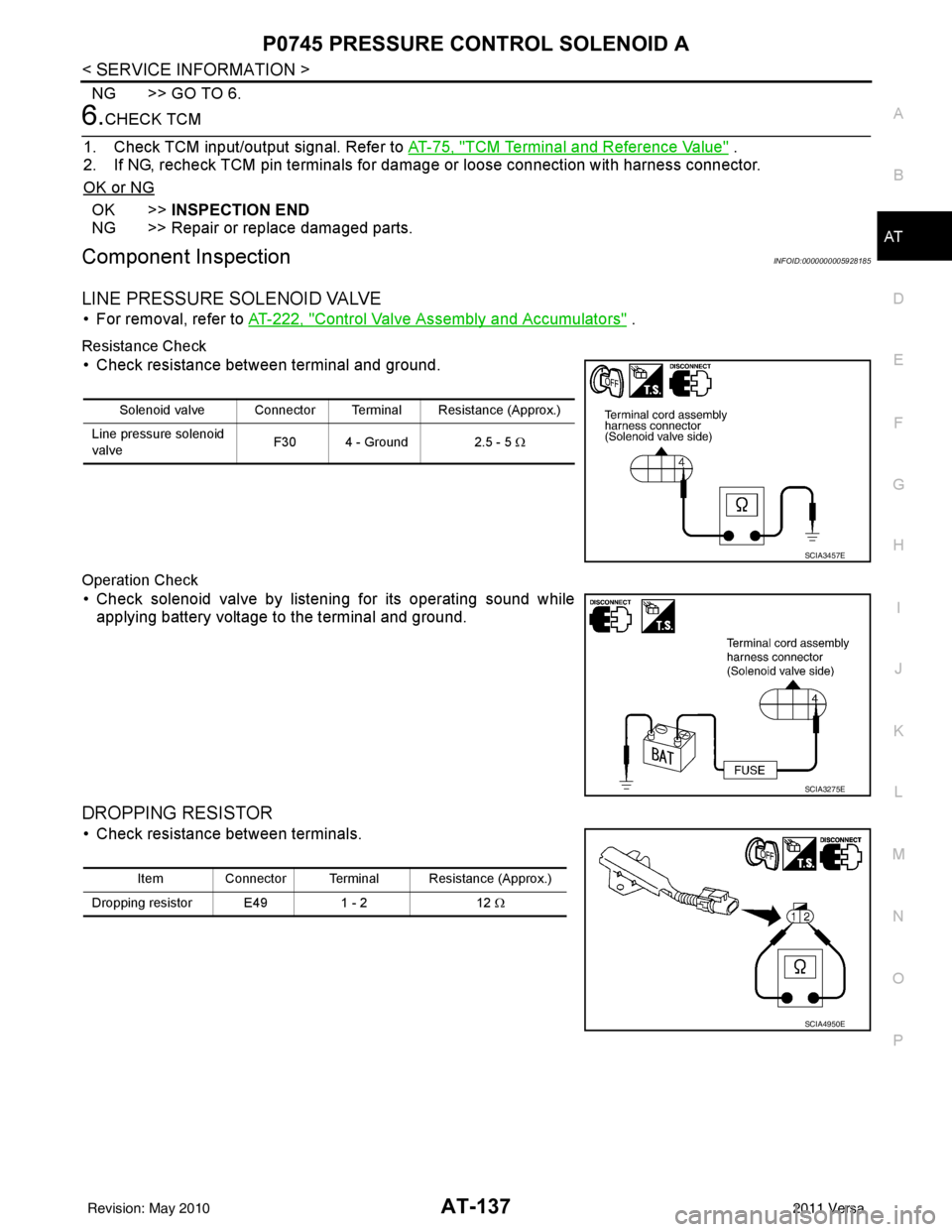
Component InspectionINFOID:0000000005928185
LINE PRESSURE SOLENOID VALVE
• For removal, refer to AT-222, "Control Valve Assembly and Accumulators" .
Resistance Check
• Check resistance between terminal and ground.
Operation Check
• Check solenoid valve by listening for its operating sound while applying battery voltage to the terminal and ground.
DROPPING RESISTOR
• Check resistance between terminals.
Solenoid valve Connector Terminal Resistance (Approx.)
Line pressure solenoid
valve F30 4 - Ground
2.5 - 5 Ω
SCIA3457E
SCIA3275E
Item Connector Terminal Resistance (Approx.)
Dropping resistor E49 1 - 212 Ω
SCIA4950E
Revision: May 2010 2011 Versa
Page 157 of 3787
AT-140
< SERVICE INFORMATION >
P0750 SHIFT SOLENOID A
Diagnosis Procedure
INFOID:0000000005928192
1.CHECK INPUT SIGNAL
With CONSULT-III
1. Start engine.
2. Select “MAIN SIGNALS” in “DATA MONITO R” mode for “TRANSMISSION” with CONSULT-III.
3. Read out the value of “SHIFT S/V A” while driving. Check the value changes according to driving speed.
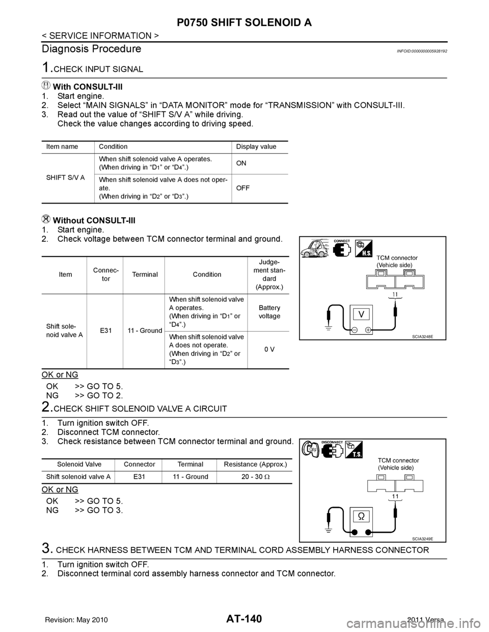
Without CONSULT-III
1. Start engine.
2. Check voltage between TCM connector terminal and ground.
OK or NG
OK >> GO TO 5.
NG >> GO TO 2.
2.CHECK SHIFT SOLENOID VALVE A CIRCUIT
1. Turn ignition switch OFF.
2. Disconnect TCM connector.
3. Check resistance between TCM connector terminal and ground.
OK or NG
OK >> GO TO 5.
NG >> GO TO 3.
3. CHECK HARNESS BETWEEN TCM AND TERM INAL CORD ASSEMBLY HARNESS CONNECTOR
1. Turn ignition switch OFF.
2. Disconnect terminal cord assembly harness connector and TCM connector.
Item name Condition Display value
SHIFT S/V A When shift solenoid valve A operates.
(When driving in “D
1” or “D4”.)
ON
When shift solenoid valve A does not oper-
ate.
(When driving in “D
2” or “D3”.) OFF
Item
Connec-
tor Terminal
Condition Judge-
ment stan-
dard
(Approx.)
Shift sole-
noid valve A E31 11 - Ground When shift solenoid valve
A operates.
(When driving in “D
1” or
“D
4”.) Battery
voltage
When shift solenoid valve
A does not operate.
(When driving in “D
2” or
“D
3”.) 0 V
SCIA3248E
Solenoid Valve Connector Terminal Resistance (Approx.)
Shift solenoid valve A E31 11 - Ground 20 - 30 Ω
SCIA3249E
Revision: May 2010 2011 Versa
Page 159 of 3787
AT-142
< SERVICE INFORMATION >
P0750 SHIFT SOLENOID A
• Check resistance between terminal and ground.
Operation Check
• Check solenoid valve by listening for its operating sound whileapplying battery voltage to the terminal and ground.
Solenoid valve Connector Terminal Resistance (Approx.)
Shift solenoid valve A F30 2 - Ground 20 - 30 Ω
SCIA2049E
SCIA2052E
Revision: May 2010 2011 Versa
Page 162 of 3787
P0755 SHIFT SOLENOID BAT-145
< SERVICE INFORMATION >
DE
F
G H
I
J
K L
M A
B
AT
N
O P
Diagnosis ProcedureINFOID:0000000005928200
1.CHECK INPUT SIGNALWith CONSULT-III
1. Start engine.
2. Select “MAIN SIGNALS” in “DATA MONITOR” mode for “TRANSMISSION” with CONSULT-III.
3. Read out the value of “SHIFT S/V B” while driving. Check the value changes according to driving speed.
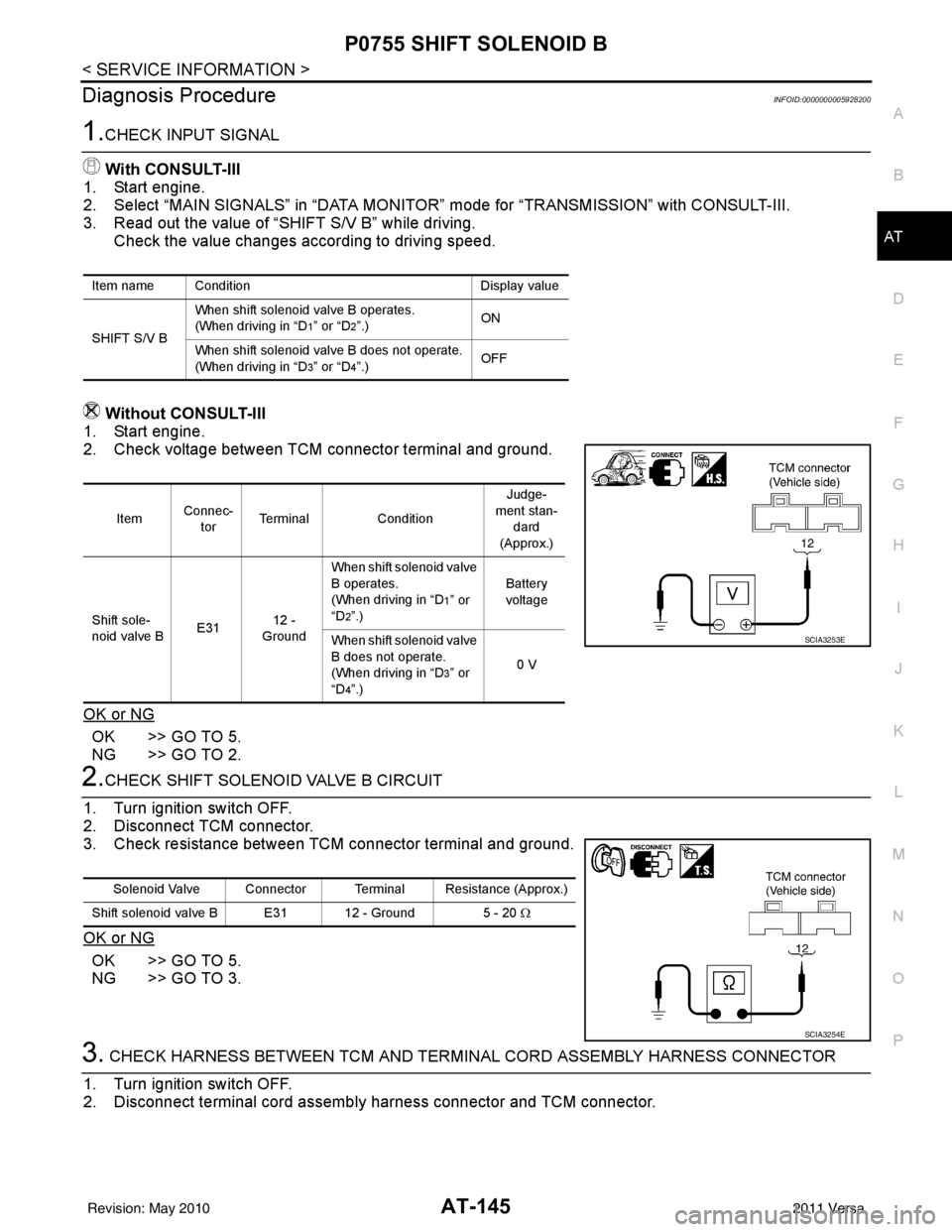
Without CONSULT-III
1. Start engine.
2. Check voltage between TCM connector terminal and ground.
OK or NG
OK >> GO TO 5.
NG >> GO TO 2.
2.CHECK SHIFT SOLENOID VALVE B CIRCUIT
1. Turn ignition switch OFF.
2. Disconnect TCM connector.
3. Check resistance between TCM connector terminal and ground.
OK or NG
OK >> GO TO 5.
NG >> GO TO 3.
3. CHECK HARNESS BETWEEN TCM AND TERMINAL CORD ASSEMBLY HARNESS CONNECTOR
1. Turn ignition switch OFF.
2. Disconnect terminal cord assemb ly harness connector and TCM connector.
Item name Condition Display value
SHIFT S/V B When shift solenoid valve B operates.
(When driving in “D
1” or “D2”.)
ON
When shift solenoid valve B does not operate.
(When driving in “D
3” or “D4”.) OFF
Item
Connec-
tor Terminal
Condition Judge-
ment stan- dard
(Approx.)
Shift sole-
noid valve B E3112 -
Ground When shift solenoid valve
B operates.
(When driving in “D
1” or
“D
2”.) Battery
voltage
When shift solenoid valve
B does not operate.
(When driving in “D
3” or
“D
4”.) 0 V
SCIA3253E
Solenoid Valve Connector Terminal Resistance (Approx.)
Shift solenoid valve B E31 12 - Ground 5 - 20 Ω
SCIA3254E
Revision: May 2010 2011 Versa
Page 164 of 3787
P0755 SHIFT SOLENOID BAT-147
< SERVICE INFORMATION >
DE
F
G H
I
J
K L
M A
B
AT
N
O P
• Check resistance between terminal and ground.
Operation Check
• Check solenoid valve by listening for its operating sound while applying battery voltage to the terminal and ground.
Solenoid valve Connector Terminal Resistance (Approx.)
Shift solenoid valve B F30 1 - Ground 5 - 20 Ω
SCIA2055E
SCIA2058E
Revision: May 2010 2011 Versa
Page 167 of 3787
AT-150
< SERVICE INFORMATION >
P1760 OVERRUN CLUTCH SOLENOID
Diagnosis Procedure
INFOID:0000000005928208
1.CHECK INPUT SIGNAL
With CONSULT-III
1. Start engine.
2. Select “MAIN SIGNALS” in “DATA MONITO R” mode for “TRANSMISSION” with CONSULT-III.
3. Read out the value of “OVERRUN/C S/V” while driving. Check the value changes according to driving speed.
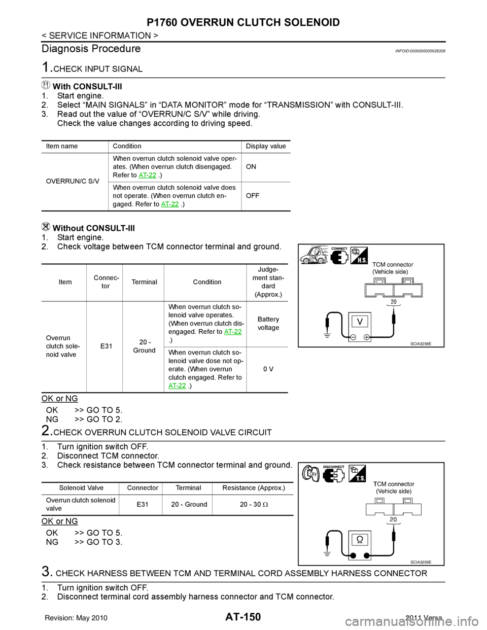
Without CONSULT-III
1. Start engine.
2. Check voltage between TCM connector terminal and ground.
OK or NG
OK >> GO TO 5.
NG >> GO TO 2.
2.CHECK OVERRUN CLUTCH SOLENOID VALVE CIRCUIT
1. Turn ignition switch OFF.
2. Disconnect TCM connector.
3. Check resistance between TCM connector terminal and ground.
OK or NG
OK >> GO TO 5.
NG >> GO TO 3.
3. CHECK HARNESS BETWEEN TCM AND TERM INAL CORD ASSEMBLY HARNESS CONNECTOR
1. Turn ignition switch OFF.
2. Disconnect terminal cord assembly harness connector and TCM connector.
Item name Condition Display value
OVERRUN/C S/V When overrun clutch solenoid valve oper-
ates. (When overrun clutch disengaged.
Refer to
AT- 2 2
.) ON
When overrun clutch solenoid valve does
not operate. (When overrun clutch en-
gaged. Refer to AT- 2 2
.) OFF
Item
Connec-
tor Terminal
Condition Judge-
ment stan- dard
(Approx.)
Overrun
clutch sole-
noid valve E31
20 -
Ground When overrun clutch so-
lenoid valve operates.
(When overrun clutch dis-
engaged. Refer to AT- 2 2
.) Battery
voltage
When overrun clutch so-
lenoid valve dose not op-
erate. (When overrun
clutch engaged. Refer to
AT- 2 2
.) 0 V
SCIA3258E
Solenoid Valve Connector Terminal Resistance (Approx.)
Overrun clutch solenoid
valve E31 20 - Ground 20 - 30 Ω
SCIA3259E
Revision: May 2010
2011 Versa
Page 169 of 3787
AT-152
< SERVICE INFORMATION >
P1760 OVERRUN CLUTCH SOLENOID
• Check resistance between terminal and ground.
Operation Check
• Check solenoid valve by listening for its operating sound whileapplying battery voltage to the terminal and ground.
Solenoid valve Connector Terminal Resistance (Approx.)
Overrun clutch solenoid
valve F30 3 - Ground 20 - 30
Ω
SCIA2059E
SCIA2062E
Revision: May 2010 2011 Versa
Page 175 of 3787
AT-158
< SERVICE INFORMATION >
BATT/FLUID TEMP SEN
Diagnosis Procedure
INFOID:0000000005928223
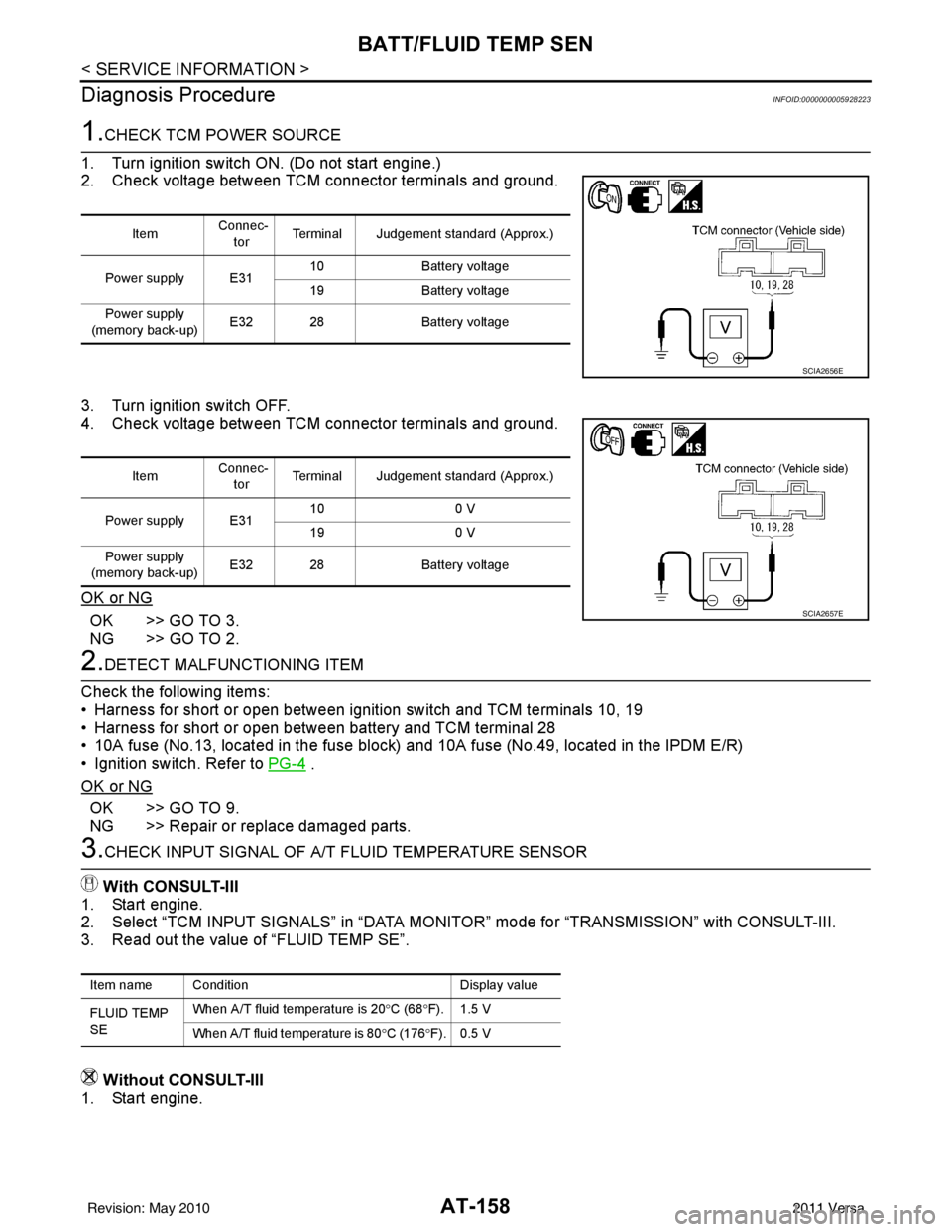
1.CHECK TCM POWER SOURCE
1. Turn ignition switch ON. (Do not start engine.)
2. Check voltage between TCM connector terminals and ground.
3. Turn ignition switch OFF.
4. Check voltage between TCM connector terminals and ground.
OK or NG
OK >> GO TO 3.
NG >> GO TO 2.
2.DETECT MALFUNCTIONING ITEM
Check the following items:
• Harness for short or open between ignition switch and TCM terminals 10, 19
• Harness for short or open between battery and TCM terminal 28
• 10A fuse (No.13, located in the fuse block) and 10A fuse (No.49, located in the IPDM E/R)
• Ignition switch. Refer to PG-4
.
OK or NG
OK >> GO TO 9.
NG >> Repair or replace damaged parts.
3.CHECK INPUT SIGNAL OF A/ T FLUID TEMPERATURE SENSOR
With CONSULT-III
1. Start engine.
2. Select “TCM INPUT SIGNALS” in “DATA MONITOR” mode for “TRANSMISSION” with CONSULT-III.
3. Read out the value of “FLUID TEMP SE”.
Without CONSULT-III
1. Start engine.
Item Connec-
tor Terminal Judgement standard (Approx.)
Power supply E31 10
Battery voltage
19 Battery voltage
Power supply
(memory back-up) E32 28
Battery voltage
SCIA2656E
Item Connec-
tor Terminal Judgement standard (Approx.)
Power supply E31 10
0 V
19 0 V
Power supply
(memory back-up) E32 28
Battery voltage
SCIA2657E
Item name Condition Display value
FLUID TEMP
SE When A/T fluid temperature is 20
°C (68 °F). 1.5 V
When A/T fluid temperature is 80 °C (176 °F). 0.5 V
Revision: May 2010 2011 Versa