2011 NISSAN TIIDA battery
[x] Cancel search: batteryPage 57 of 3787
AT-40
< SERVICE INFORMATION >
ON BOARD DIAGNOSTIC (OBD) SYSTEM
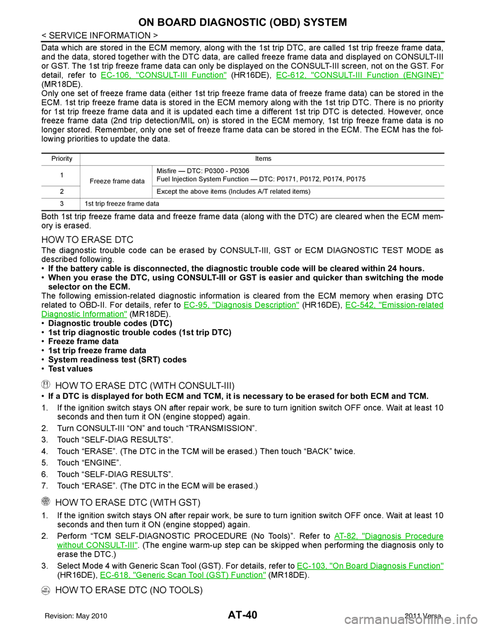
Data which are stored in the ECM memory, along with the 1st trip DTC, are called 1st trip freeze frame data,
and the data, stored together with the DTC data, are called freeze frame data and displayed on CONSULT-III
or GST. The 1st trip freeze frame data can only be disp layed on the CONSULT-III screen, not on the GST. For
detail, refer to EC-106, "
CONSULT-III Function" (HR16DE), EC-612, "CONSULT-III Function (ENGINE)"
(MR18DE).
Only one set of freeze frame data (either 1st trip freeze frame data of freeze frame data) can be stored in the
ECM. 1st trip freeze frame data is stored in the ECM memory along with the 1st trip DTC. There is no priority
for 1st trip freeze frame data and it is updated each time a different 1st trip DTC is detected. However, once
freeze frame data (2nd trip detection/MIL on) is stored in the ECM memory, 1st trip freeze frame data is no
longer stored. Remember, only one set of freeze frame data can be stored in the ECM. The ECM has the fol-
lowing priorities to update the data.
Both 1st trip freeze frame data and freeze frame dat a (along with the DTC) are cleared when the ECM mem-
ory is erased.
HOW TO ERASE DTC
The diagnostic trouble code can be erased by CONSULT- III, GST or ECM DIAGNOSTIC TEST MODE as
described following.
• If the battery cable is disconnected, the diagnosti c trouble code will be cleared within 24 hours.
• When you erase the DTC, using CONSULT-III or GS T is easier and quicker than switching the mode
selector on the ECM.
The following emission-related diagnostic information is cleared from the ECM memory when erasing DTC
related to OBD-II. For details, refer to EC-95, "
Diagnosis Description" (HR16DE), EC-542, "Emission-related
Diagnostic Information" (MR18DE).
• Diagnostic trouble codes (DTC)
• 1st trip diagnostic trou ble codes (1st trip DTC)
• Freeze frame data
• 1st trip freeze frame data
• System readiness test (SRT) codes
• Test values
HOW TO ERASE DTC (WITH CONSULT-III)
•If a DTC is displayed for both ECM and TCM, it is necessary to be erased for both ECM and TCM.
1. If the ignition switch stays ON after repair work, be sure to turn ignition switch OFF once. Wait at least 10 seconds and then turn it ON (engine stopped) again.
2. Turn CONSULT-III “ON” and touch “TRANSMISSION”.
3. Touch “SELF-DIAG RESULTS”.
4. Touch “ERASE”. (The DTC in the TCM will be erased.) Then touch “BACK” twice.
5. Touch “ENGINE”.
6. Touch “SELF-DIAG RESULTS”.
7. Touch “ERASE”. (The DTC in the ECM will be erased.)
HOW TO ERASE DTC (WITH GST)
1. If the ignition switch stays ON after repair work, be sure to turn ignition switch OFF once. Wait at least 10 seconds and then turn it ON (engine stopped) again.
2. Perform “TCM SELF-DIAGNOSTIC PROCEDURE (No Tools)”. Refer to AT-82, "
Diagnosis Procedure
without CONSULT-III". (The engine warm-up step can be skipped when performing the diagnosis only\
to
erase the DTC.)
3. Select Mode 4 with Generic Scan Tool (GST). For details, refer to EC-103, "
On Board Diagnosis Function"
(HR16DE), EC-618, "Generic Scan Tool (GST) Function" (MR18DE).
HOW TO ERASE DTC (NO TOOLS)
Priority Items
1 Freeze frame data Misfire — DTC: P0300 - P0306
Fuel Injection System Function — DTC: P0171, P0172, P0174, P0175
2 Except the above items (Includes A/T related items)
3 1st trip freeze frame data
Revision: May 2010 2011 Versa
Page 93 of 3787
AT-76
< SERVICE INFORMATION >
TROUBLE DIAGNOSIS
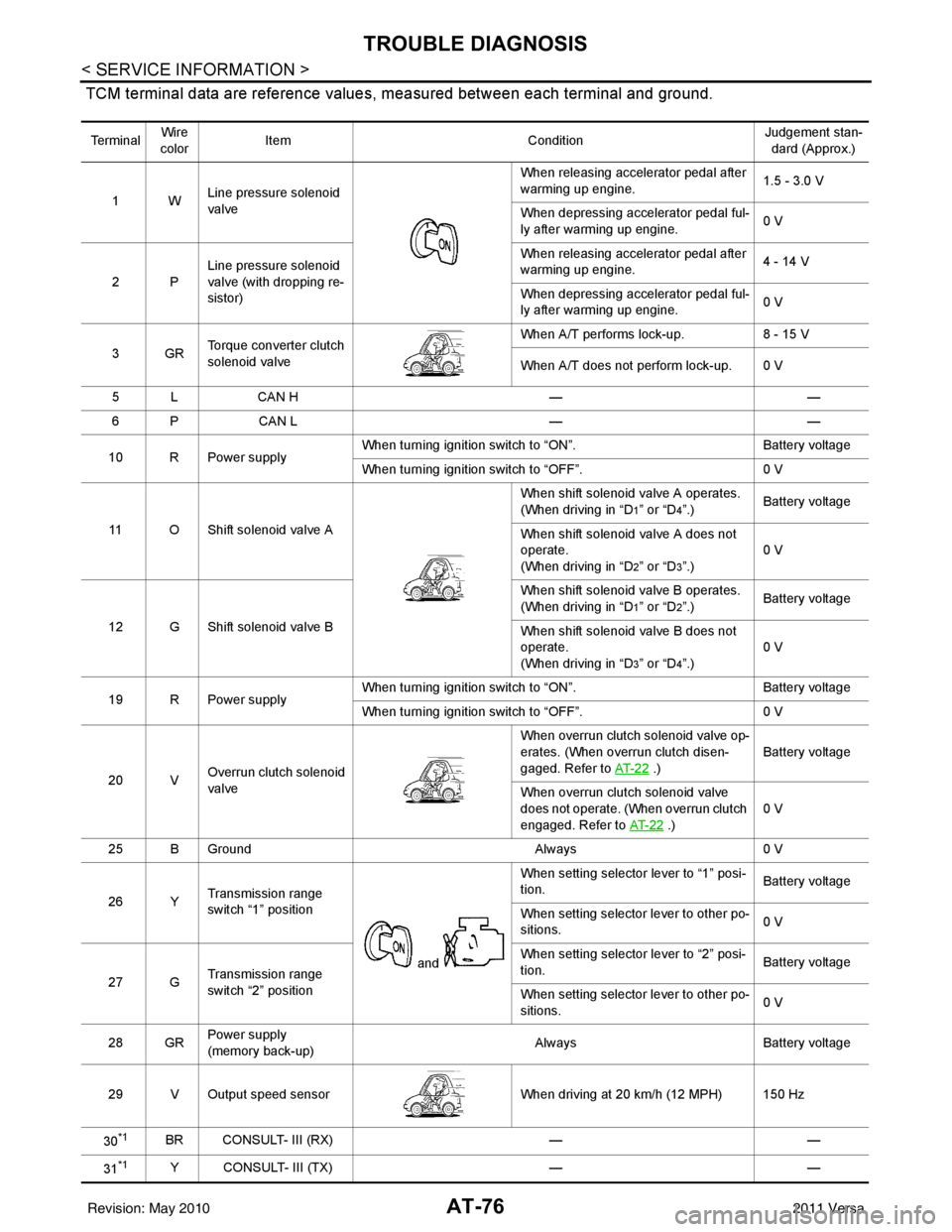
TCM terminal data are reference values, measured between each terminal and ground.
Te r m i n a lWire
color Item
ConditionJudgement stan-
dard (Approx.)
1W Line pressure solenoid
valve When releasing accelerator pedal after
warming up engine.
1.5 - 3.0 V
When depressing accelerator pedal ful-
ly after warming up engine. 0 V
2P Line pressure solenoid
valve (with dropping re-
sistor) When releasing accelerator pedal after
warming up engine.
4 - 14 V
When depressing accelerator pedal ful-
ly after warming up engine. 0 V
3GR Torque converter clutch
solenoid valve When A/T performs lock-up.
8 - 15 V
When A/T does not perform lock-up. 0 V
5 L CAN H ——
6 P CAN L ——
10 R Power supply When turning ignition switch to “ON”.
Battery voltage
When turning ignition switch to “OFF”. 0 V
11 O Shift solenoid valve A When shift solenoid valve A operates.
(When driving in “D
1” or “D4”.)
Battery voltage
When shift solenoid valve A does not
operate.
(When driving in “D
2” or “D3”.) 0 V
12 G Shift solenoid valve B When shift solenoid valve B operates.
(When driving in “D
1” or “D2”.)
Battery voltage
When shift solenoid valve B does not
operate.
(When driving in “D
3” or “D4”.) 0 V
19 R Power supply When turning ignition switch to “ON”.
Battery voltage
When turning ignition switch to “OFF”. 0 V
20 V Overrun clutch solenoid
valve When overrun clutch solenoid valve op-
erates. (When overrun clutch disen-
gaged. Refer to
AT- 2 2
.) Battery voltage
When overrun clutch solenoid valve
does not operate. (When overrun clutch
engaged. Refer to AT- 2 2
.)0 V
25 B Ground Always0 V
26 Y Transmission range
switch “1” position
and When setting selector lever to “1” posi-
tion.
Battery voltage
When setting selector lever to other po-
sitions. 0 V
27 G Transmission range
switch “2” position When setting selector lever to “2” posi-
tion.
Battery voltage
When setting selector lever to other po-
sitions. 0 V
28 GR Power supply
(memory back-up) Always
Battery voltage
29 V Output speed sensor When driving at 20 km/h (12 MPH) 150 Hz
30
*1BR CONSULT- III (RX) ——
31
*1Y CONSULT- III (TX) ——
Revision: May 2010 2011 Versa
Page 94 of 3787
TROUBLE DIAGNOSISAT-77
< SERVICE INFORMATION >
DE
F
G H
I
J
K L
M A
B
AT
N
O P
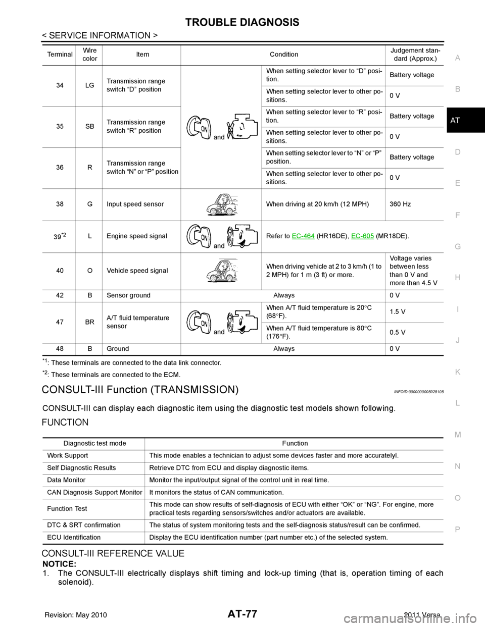
*1: These terminals are connected to the data link connector.
*2: These terminals are connected to the ECM.
CONSULT-III Function (TRANSMISSION)INFOID:0000000005928105
CONSULT-III can display each diagnostic item using the diagnostic test models shown following.
FUNCTION
CONSULT-III REFERENCE VALUE
NOTICE:
1. The CONSULT-III electrically displays shift timi ng and lock-up timing (that is, operation timing of each
solenoid).
34 LG Transmission range
switch “D” position
and When setting selector lever to “D” posi-
tion.
Battery voltage
When setting selector lever to other po-
sitions. 0 V
35 SB Transmission range
switch “R” position When setting selector lever to “R” posi-
tion.
Battery voltage
When setting selector lever to other po-
sitions. 0 V
36 R Transmission range
switch “N” or “P” position When setting selector
lever to “N” or “P”
position. Battery voltage
When setting selector lever to other po-
sitions. 0 V
38 G Input speed sensor When driving at 20 km/h (12 MPH) 360 Hz
39
*2L Engine speed signal and Refer to EC-464 (HR16DE),
EC-605 (MR18DE).
40 O Vehicle speed signal When driving vehicle at 2 to 3 km/h (1 to
2 MPH) for 1 m (3 ft) or more.Voltage varies
between less
than 0 V and
more than 4.5 V
42 B Sensor ground Always0 V
47 BR A/T fluid temperature
sensor
and When A/T fluid temperature is 20°
C
(68 °F). 1.5 V
When A/T fluid temperature is 80° C
(176 °F). 0.5 V
48 B Ground Always0 V
Te r m i n a l
Wire
color Item
ConditionJudgement stan-
dard (Approx.)
Diagnostic test mode Function
Work Support This mode enables a technician to adjust some devices faster and more accuratelyI.
Self Diagnostic Results Retrieve DTC from ECU and display diagnostic items.
Data Monitor Monitor the input/output signal of the control unit in real time.
CAN Diagnosis Support Monitor It monitors the status of CAN communication.
Function Test This mode can show results of self-diagnosis of ECU with either “OK” or “NG”. For engine, more
practical tests regarding sensors/switches and/or actuators are available.
DTC & SRT confirmation The status of system monitoring tests and the self-diagnosis status/result can be confirmed.
ECU Identification Display the ECU identification number (part number etc.) of the selected system.
Revision: May 2010 2011 Versa
Page 95 of 3787

AT-78
< SERVICE INFORMATION >
TROUBLE DIAGNOSIS
Check for time difference between actual shift timing and the CONSULT-III display. If the difference is
noticeable, mechanical parts (except solenoids, sens ors, etc.) may be malfunctioning. Check mechanical
parts using applicable diagnostic procedures.
2. Shift schedule (which implies gear position) display ed on CONSULT-III and that indicated in Service Man-
ual may differ slightly. This occurs because of the following reasons:
- Actual shift schedule has more or less tolerance or allowance,
- Shift schedule indicated in Service Manual refers to the point where shifts start, and
- Gear position displayed on CONSULT-III indicates the point where shifts are completed.
3. Shift solenoid valve “A” or “B” is displayed on CONSUL T-III at the start of shifting. Gear position is dis-
played upon completion of shifting (which is computed by TCM).
Item name Condition Display value (Approx.)
VHCL/S SE-A/T During driving Approximately matches the speedometer
reading.
VHCL/S SE-MTR
THROTTLE POSI Released accelerator pedal.
0.0/8
Fully depressed accelerator pedal. 8.0/8
FLUID TEMP SE When A/T fluid temperature is 20
°C (68 °F). 1.5 V
When A/T fluid temperature is 80 °C (176 °F). 0.5 V
BATTERY VOLT When turning ignition switch to “ON”. Battery voltage
ENGINE SPEED Engine running Approximately matches the tachometer
reading.
INPUT SPEED During driving (lock-up ON) Approximately matche s the engine speed.
OVERDRIVE SW When overdrive control switch is depressed. ON
When overdrive control switch is released. OFF
PN POSI SW When setting selector lever
to “N” or “P” position. ON
When setting selector lever to other positions. OFF
R POSITION SW When setting selector lever to “R” position. ON
When setting selector lever to other positions. OFF
D POSITION SW When setting selector lever to “D” position. ON
When setting selector lever to other positions. OFF
2 POSITION SW When setting selector lever to “2” position. ON
When setting selector lever to other positions. OFF
1 POSITION SW When setting selector lever to “1” position. ON
When setting selector lever to other positions. OFF
CLOSED THL/SW Released accelerator pedal.
ON
Depressed accelerator pedal. OFF
W/O THRL/P-SW Fully depressed accelerator pedal.
ON
Released accelerator pedal. OFF
SHIFT S/V A When shift solenoid valve A operates.
(When driving in “D
1” or “D4”.)
ON
When shift solenoid valve A does not operate.
(When driving in “D
2” or “D3”.) OFF
SHIFT S/V B When shift solenoid valve B operates.
(When driving in “D
1” or “D2”.)
ON
When shift solenoid valve B does not operate.
(When driving in “D
3” or “D4”.) OFF
Revision: May 2010
2011 Versa
Page 97 of 3787
AT-80
< SERVICE INFORMATION >
TROUBLE DIAGNOSIS
*1: Refer to AT- 4 1 , "Malfunction Indicator Lamp (MIL)" .
*2: These malfunctions cannot be displayed MIL if another malfunction is assigned to MIL.
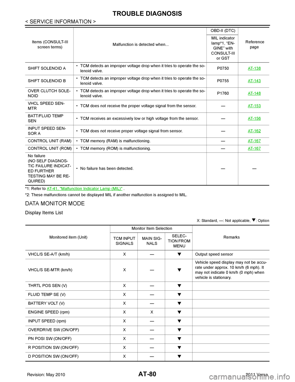
DATA MONITOR MODE
Display Items List
X: Standard, —: Not applicable, : Option
SHIFT SOLENOID A • TCM detects an improper voltage drop when it tries to operate the so-
lenoid valve. P0750
AT- 1 3 8
SHIFT SOLENOID B • TCM detects an improper voltage drop when it tries to operate the so-
lenoid valve. P0755
AT- 1 4 3
OVER CLUTCH SOLE-
NOID • TCM detects an improper voltage drop when it tries to operate the so-
lenoid valve. P1760
AT- 1 4 8
VHCL SPEED SEN-
MTR • TCM does not receive the proper voltage signal from the sensor.
—AT- 1 5 3
BATT/FLUID TEMP
SEN • TCM receives an excessively low or high voltage from the sensor.
—AT- 1 5 6
INPUT SPEED SEN-
SOR A • TCM does not receive proper voltage signal from sensor.
—AT- 1 6 2
CONTROL UNIT (RAM) • TCM memory (RAM) is malfunctioning. —AT- 1 6 7
CONTROL UNIT (ROM) • TCM memory (ROM) is malfunctioning. —AT- 1 6 7
No failure
(NO SELF DIAGNOS-
TIC FAILURE INDICAT-
ED FURTHER
TESTING MAY BE RE-
QUIRED) • No failure has been detected.
——
Items (CONSULT-III
screen terms) Malfunction is detected when... OBD-II (DTC)
Reference page
MIL indicator
lamp*1, “EN-
GINE” with
CONSULT-III or GST
Monitored item (Unit) Monitor Item Selection
Remarks
TCM INPUT
SIGNALS MAIN SIG-
NALS SELEC-
TION FROM MENU
VHCL/S SE-A/T (km/h) X— Output speed sensor
VHCL/S SE-MTR (km/h) X— Vehicle speed display may not be accu-
rate under approx. 10 km/h (6 mph). It
may not indicate 0 km/h (0 mph) when
vehicle is stationary.
THRTL POS SEN (V) X—
FLUID TEMP SE (V) X—
BATTERY VOLT (V) X—
ENGINE SPEED (rpm) XX
INPUT SPEED (rpm) X—
OVERDRIVE SW (ON/OFF) X—
PN POSI SW (ON/OFF) X—
R POSITION SW (ON/OFF) X—
D POSITION SW (ON/OFF) X—
Revision: May 2010 2011 Versa
Page 109 of 3787
AT-92
< SERVICE INFORMATION >
P0705 TRANSMISSION RANGE SWITCH A
Diagnosis Procedure
INFOID:0000000005928119
1.CHECK INPUT SIGNAL
With CONSULT-III
1. Turn ignition switch ON. (Do not start engine.)
2. Select “TCM INPUT SIGNALS” in “DATA MONITOR” mode for “TRANSMISSION” with CONSULT-III.
3. Read out “P·N”, “R”, “D”, “2” and “1” position switches moving selector lever to each position.
OK or NG
OK >> GO TO 6.
NG >> GO TO 3.
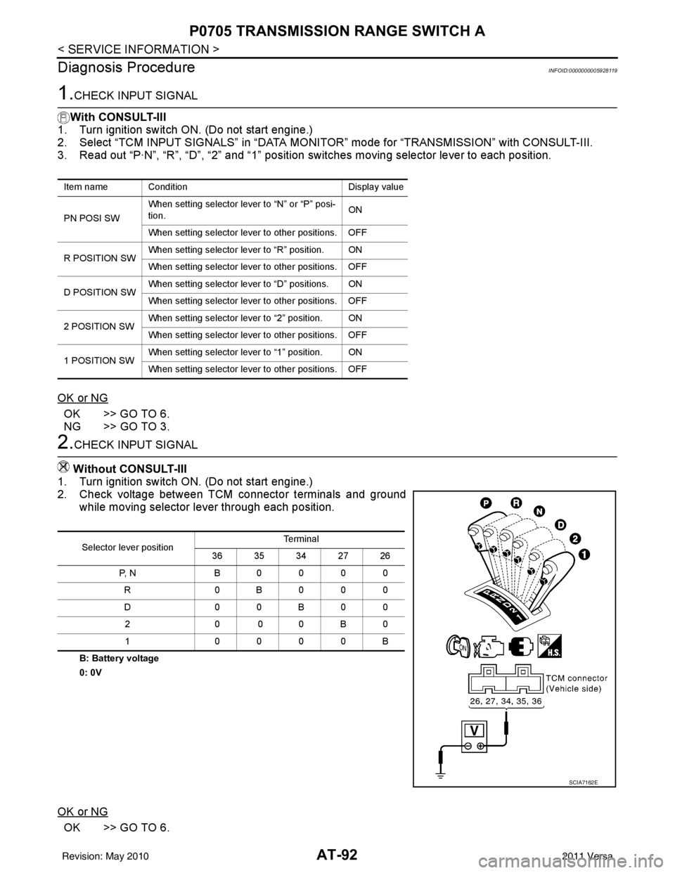
2.CHECK INPUT SIGNAL
Without CONSULT-III
1. Turn ignition switch ON. (Do not start engine.)
2. Check voltage between TCM connector terminals and ground while moving selector lever through each position.
B: Battery voltage
0: 0V
OK or NG
OK >> GO TO 6.
Item name Condition Display value
PN POSI SW When setting selector le
ver to “N” or “P” posi-
tion. ON
When setting selector lever to other positions. OFF
R POSITION SW When setting selector lever to “R” position. ON
When setting selector lever to other positions. OFF
D POSITION SW When setting selector lever to “D” positions. ON
When setting selector lever to other positions. OFF
2 POSITION SW When setting selector lever to “2” position. ON
When setting selector lever to other positions. OFF
1 POSITION SW When setting selector lever to “1” position. ON
When setting selector lever to other positions. OFF
Selector lever position Te r m i n a l
36 35 34 27 26
P, N B0000 R 0B000
D0 0B 00
20 00B 0
1 0000B
SCIA7162E
Revision: May 2010 2011 Versa
Page 119 of 3787
AT-102
< SERVICE INFORMATION >
P0720 OUTPUT SPEED SENSOR
TCM TERMINALS AND REFERENCE VALUES
Refer to AT-75, "TCM Terminal and Reference Value".
Diagnosis ProcedureINFOID:0000000005928135
1.CHECK INPUT SIGNAL
With CONSULT-III
1. Start engine.
2. Select “TCM INPUT SIGNALS” in “DATA MONITOR” mode for “TRANSMISSION” with CONSULT-III.
3. Read out the value of “VHCL/S SE-A/T” while driving. Check the value changes according to driving speed.
OK or NG
OK >> GO TO 8.
NG >> GO TO 2.
2. CHECK OUTPUT SPEED SENSOR
With CONSULT-III
1. Start engine.
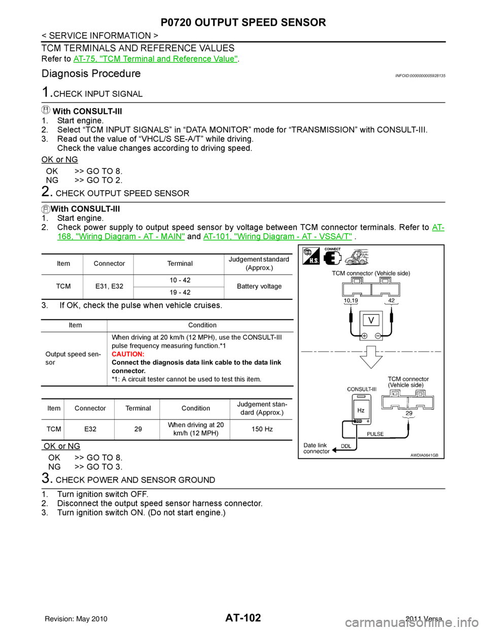
2. Check power supply to output speed sensor by voltage between TCM connector terminals. Refer to AT-
168, "Wiring Diagram - AT - MAIN" and AT-101, "Wiring Diagram - AT - VSSA/T" .
3. If OK, check the pulse when vehicle cruises.
OK or NG
OK >> GO TO 8.
NG >> GO TO 3.
3. CHECK POWER AND SENSOR GROUND
1. Turn ignition switch OFF.
2. Disconnect the output speed sensor harness connector.
3. Turn ignition switch ON. (Do not start engine.)
Item Connector TerminalJudgement standard
(Approx.)
TCM E31, E32 10 - 42
Battery voltage
19 - 42
Item Condition
Output speed sen-
sor When driving at 20 km/h (12 MPH), use the CONSULT-III
pulse frequency measuring function.*1
CAUTION:
Connect the diagnosis
data link cable to the data link
connector.
*1: A circuit tester cannot be used to test this item.
Item Connector Terminal Condition Judgement stan-
dard (Approx.)
TCM E32 29When driving at 20
km/h (12 MPH) 150 Hz
AWDIA0641GB
Revision: May 2010
2011 Versa
Page 120 of 3787
P0720 OUTPUT SPEED SENSORAT-103
< SERVICE INFORMATION >
DE
F
G H
I
J
K L
M A
B
AT
N
O P
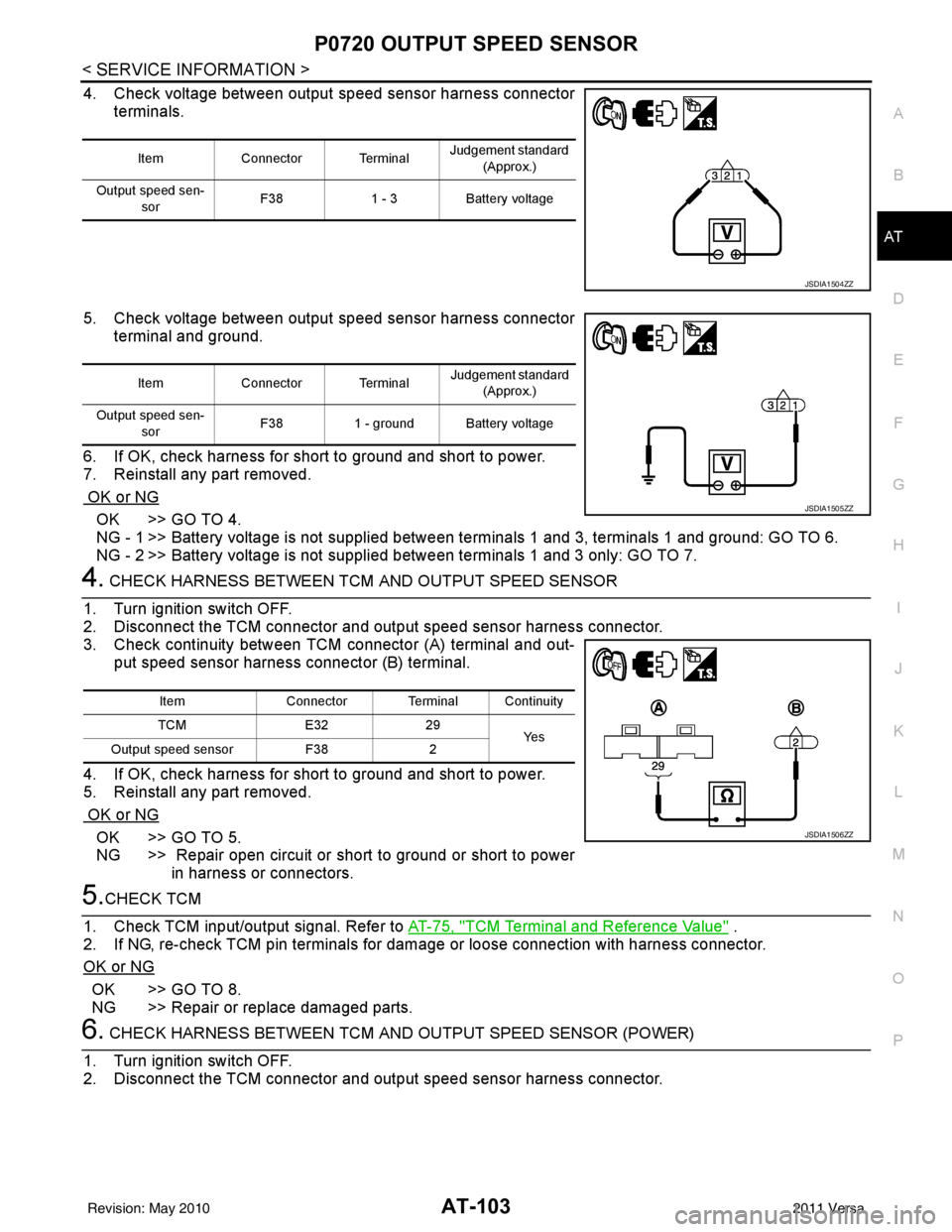
4. Check voltage between output speed sensor harness connector terminals.
5. Check voltage between output speed sensor harness connector terminal and ground.
6. If OK, check harness for short to ground and short to power.
7. Reinstall any part removed.
OK or NG
OK >> GO TO 4.
NG - 1 >> Battery voltage is not supplied between terminals 1 and 3, terminals 1 and ground: GO TO 6.
NG - 2 >> Battery voltage is not supplied between terminals 1 and 3 only: GO TO 7.
4. CHECK HARNESS BETWEEN TCM AND OUTPUT SPEED SENSOR
1. Turn ignition switch OFF.
2. Disconnect the TCM connector and output speed sensor harness connector.
3. Check continuity between TCM connector (A) terminal and out- put speed sensor harness connector (B) terminal.
4. If OK, check harness for short to ground and short to power.
5. Reinstall any part removed.
OK or NG
OK >> GO TO 5.
NG >> Repair open circuit or short to ground or short to power in harness or connectors.
5.CHECK TCM
1. Check TCM input/output signal. Refer to AT-75, "
TCM Terminal and Reference Value" .
2. If NG, re-check TCM pin terminals for dam age or loose connection with harness connector.
OK or NG
OK >> GO TO 8.
NG >> Repair or replace damaged parts.
6. CHECK HARNESS BETWEEN TCM AND OUTPUT SPEED SENSOR (POWER)
1. Turn ignition switch OFF.
2. Disconnect the TCM connector and output speed sensor harness connector.
Item Connector Terminal Judgement standard
(Approx.)
Output speed sen- sor F38
1 - 3Battery voltage
JSDIA1504ZZ
Item Connector Terminal Judgement standard
(Approx.)
Output speed sen- sor F38
1 - ground Battery voltage
JSDIA1505ZZ
Item Connector Terminal Continuity
TCM E3229
Ye s
Output speed sensor F382
JSDIA1506ZZ
Revision: May 2010 2011 Versa