2011 NISSAN TIIDA Torque rod
[x] Cancel search: Torque rodPage 2616 of 3787
![NISSAN TIIDA 2011 Service Repair Manual EM-226
< SERVICE INFORMATION >[MR18DE]
CYLINDER BLOCK
• Install connecting rod bearings (2) to connecting rod (3) and con-
necting rod bearing cap (1), and tighten connecting rod bolts to the
specif NISSAN TIIDA 2011 Service Repair Manual EM-226
< SERVICE INFORMATION >[MR18DE]
CYLINDER BLOCK
• Install connecting rod bearings (2) to connecting rod (3) and con-
necting rod bearing cap (1), and tighten connecting rod bolts to the
specif](/manual-img/5/57396/w960_57396-2615.png)
EM-226
< SERVICE INFORMATION >[MR18DE]
CYLINDER BLOCK
• Install connecting rod bearings (2) to connecting rod (3) and con-
necting rod bearing cap (1), and tighten connecting rod bolts to the
specified torque. Refer to EM-203, "
Disassembly and Assembly"
for tightening procedure.
• Measure the inner diameter of connecting rod bearing with an inside micrometer.
(Bearing oil clearance) = (Connecting rod bearing inner diameter)
– (Crankshaft pin journal diameter)
• If clearance exceeds the limit, select proper connecting rod bearing according to connecting rod big end diameter and crankshaft pin journal diameter to obtain specified bearing oil clearance. Refer to EM-212,
"How to Select Piston and Bearing".
Method of Using Plastigage
• Remove engine oil and dust on crankshaft pin and the surfaces of each bearing completely.
• Cut a plastigage slightly shorter than the bearing width, and place it in crankshaft axial direction, avoiding oil
holes.
• Install connecting rod bearings to connecting rod and cap, and tighten connecting rod bolts to the specified torque. Refer to EM-203, "
Disassembly and Assembly" for the tightening procedure.
CAUTION:
Never rotate crankshaft.
• Remove connecting rod cap and bearing, and using the scale (A) on the plastigage bag, measure the plastigage width.
NOTE:
The procedure when the measured value exceeds the limit is
same as that described in the “Method by Calculation”.
MAIN BEARING OIL CLEARANCE
Method by Calculation
• Install main bearings (3) to cylinder block (1) and main bearing cap(2), and tighten main bearing cap bolts to the specified torque.
Refer to EM-203, "
Disassembly and Assembly" for the tightening
procedure.
• Measure the inner diameter of main bearing with a bore gauge.
(Bearing oil clearance) = (Main bearing inner diameter) – (Crank-
shaft main journal diameter)
A : Example
B : Inner diameter measuring direction
Standard : 0.037 - 0.047 mm (0.0015 - 0.0019 in)
Limit : 0.07 mm (0.0028 in)
PBIC3275J
PBIC3276J
A : Example
B : Inner diameter measuring direction
Standard: No. 1, 4 and 5 journals : 0.024 - 0.034 mm (0.0009 - 0.0013 in)
No. 2 and 3 journals : 0.012 - 0.022 mm (0.0005 - 0.0009 in)
Limit : 0.065 mm (0.0026 in)
PBIC3277J
Revision: May 2010 2011 Versa
Page 2617 of 3787
![NISSAN TIIDA 2011 Service Repair Manual CYLINDER BLOCKEM-227
< SERVICE INFORMATION > [MR18DE]
C
D
E
F
G H
I
J
K L
M A
EM
NP
O
• If clearance exceeds the limit, select proper main bearing according to main bearing inner diameter and
cranks NISSAN TIIDA 2011 Service Repair Manual CYLINDER BLOCKEM-227
< SERVICE INFORMATION > [MR18DE]
C
D
E
F
G H
I
J
K L
M A
EM
NP
O
• If clearance exceeds the limit, select proper main bearing according to main bearing inner diameter and
cranks](/manual-img/5/57396/w960_57396-2616.png)
CYLINDER BLOCKEM-227
< SERVICE INFORMATION > [MR18DE]
C
D
E
F
G H
I
J
K L
M A
EM
NP
O
• If clearance exceeds the limit, select proper main bearing according to main bearing inner diameter and
crankshaft main journal diameter to obtain specified bearing oil clearance. Refer to EM-212, "
How to Select
Piston and Bearing".
Method of Using Plastigage
• Remove engine oil and dust on crankshaft main journal and the surfaces of each bearing completely.
• Cut a plastigage slightly shorter than the bearing width, and place it in crankshaft axial direction, avoiding oil
holes.
• Install main bearings to cylinder block and main bearing cap, and tighten main bearing cap bolts to the spec- ified torque. Refer to EM-203, "
Disassembly and Assembly" for the tightening procedure.
CAUTION:
Never rotate crankshaft.
• Remove main bearing cap and bearings, and using the scale (A) on the plastigage bag, measure the plastigage width.
NOTE:
The procedure when the measured value exceeds the limit is
same as that described in the “Method by Calculation”.
MAIN BEARING CRUSH HEIGHT
• When main bearing cap is removed after being tightened to thespecified torque with main bearings (1) installed, the tip end of
bearing must protrude (B). Refer to EM-203, "
Disassembly and
Assembly" for the tightening procedure.
• If the standard is not met, replace main bearings.
CONNECTING ROD BEARING CRUSH HEIGHT
• When connecting rod bearing cap is removed after being tightened to the specified torque with connecting rod bearings (1) installed,
the tip end of bearing must protrude. Refer to EM-203, "
Disassem-
bly and Assembly" for the tightening procedure (B).
• If the standard is not met, replace connecting rod bearings.
MAIN BEARING CAP BOLT OUTER DIAMETER
PBIC3278J
A : Example
Standard : There must be crush height.
PBIC3279J
A : Example
Standard : There must be crush height.
PBIC3279J
Revision: May 2010 2011 Versa
Page 2696 of 3787
FRONT SUSPENSION ASSEMBLYFSU-11
< SERVICE INFORMATION >
C
DF
G H
I
J
K L
M A
B
FSU
N
O P
Removal and InstallationINFOID:0000000005930901
REMOVAL
1. Separate intermediate shaft from steering gear pinion shaft. Refer to PS-13, "Removal and Installation".
2. Remove front tires from vehicle using a power tool.
3. Remove wheel sensor from steering knuckle. Refer to BRC-33
.
CAUTION:
Do not pull on wheel sensor harness.
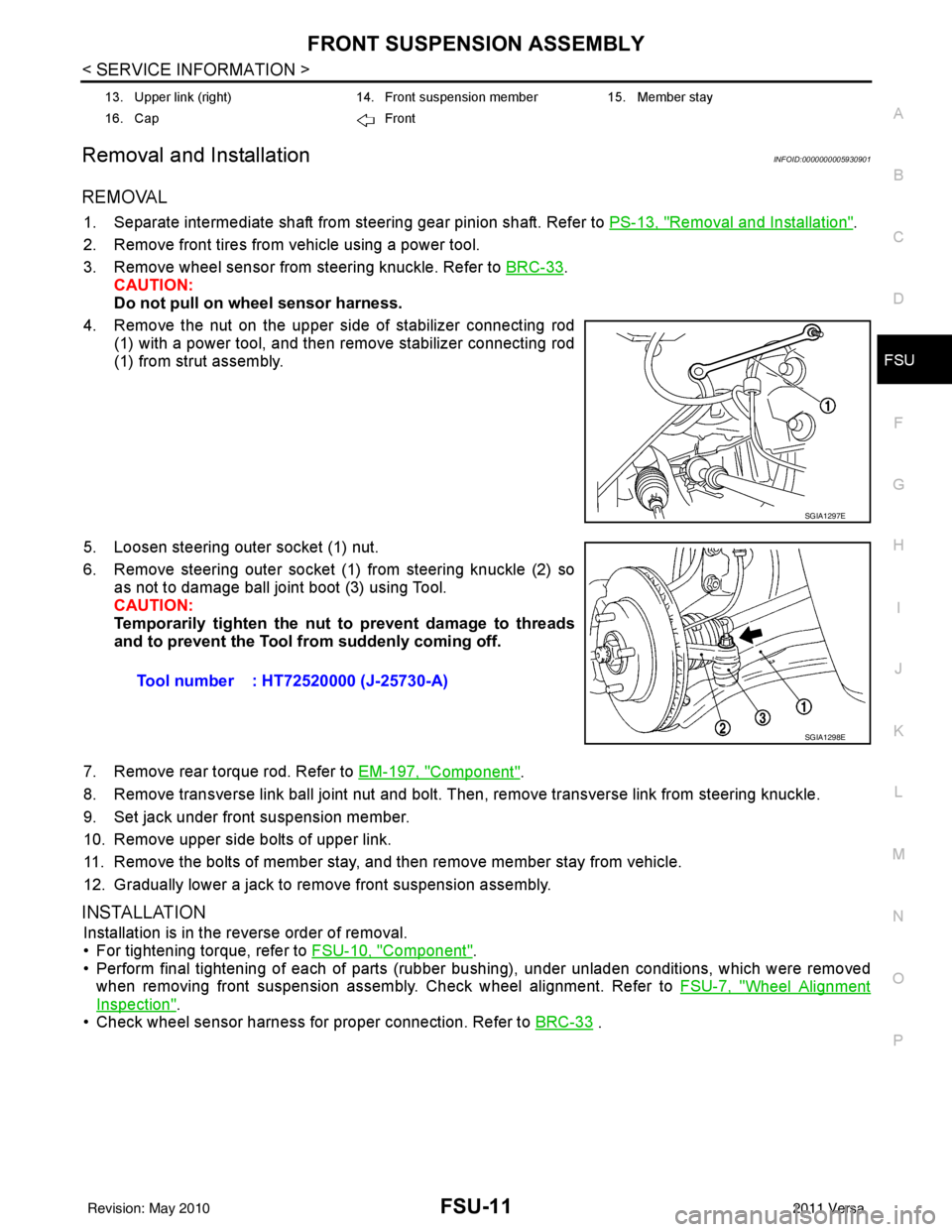
4. Remove the nut on the upper side of stabilizer connecting rod (1) with a power tool, and then remove stabilizer connecting rod
(1) from strut assembly.
5. Loosen steering outer socket (1) nut.
6. Remove steering outer socket (1) from steering knuckle (2) so as not to damage ball joint boot (3) using Tool.
CAUTION:
Temporarily tighten the nut to prevent damage to threads
and to prevent the Tool fr om suddenly coming off.
7. Remove rear torque rod. Refer to EM-197, "
Component".
8. Remove transverse link ball joint nut and bolt. Then, remove transverse link from steering knuckle.
9. Set jack under front suspension member.
10. Remove upper side bolts of upper link.
11. Remove the bolts of member stay, and then remove member stay from vehicle.
12. Gradually lower a jack to remove front suspension assembly.
INSTALLATION
Installation is in the reverse order of removal.
• For tightening torque, refer to FSU-10, "
Component".
• Perform final tightening of each of parts (rubber bushing), under unladen conditions, which were removed when removing front suspension assembly. Check wheel alignment. Refer to FSU-7, "
Wheel Alignment
Inspection".
• Check wheel sensor harness for proper connection. Refer to BRC-33
.
13. Upper link (right)14. Front suspension member15. Member stay
16. Cap Front
SGIA1297E
Tool number : HT72520000 (J-25730-A)
SGIA1298E
Revision: May 2010 2011 Versa
Page 2697 of 3787
FSU-12
< SERVICE INFORMATION >
COIL SPRING AND STRUT
COIL SPRING AND STRUT
Removal and InstallationINFOID:0000000005930902
REMOVAL
1. Remove cowl top panel. Refer to EI-24, "Removal and Installation".
2. Remove front tires using power tool.
3. Remove harness of wheel sensor from strut assembly. Refer to BRC-33, "
Removal and Installation".
CAUTION:
Do not pull on wheel sensor harness.
4. Remove brake hose lock plate. Refer to BR-12, "
Rear Brake Tube and Hose".
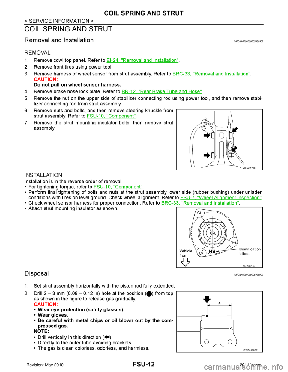
5. Remove the nut on the upper side of stabilizer connecting rod using power tool, and then remove stabi- lizer connecting rod from strut assembly.
6. Remove nuts and bolts, and then remove steering knuckle from strut assembly. Refer to FSU-10, "
Component".
7. Remove the strut mounting insulator bolts, then remove strut assembly.
INSTALLATION
Installation is in the reverse order of removal.
• For tightening torque, refer to FSU-10, "
Component".
• Perform final tightening of bolts and nuts at the strut assembly lower side (rubber bushing) under unladen
conditions with tires on level ground. Check wheel alignment. Refer to FSU-7, "
Wheel Alignment Inspection".
• Check wheel sensor harness for proper connection. Refer to BRC-33, "
Removal and Installation".
• Attach strut mounting insulator as shown.
DisposalINFOID:0000000005930903
1. Set strut assembly horizontally with the piston rod fully extended.
2. Drill 2 – 3 mm (0.08 – 0.12 in) hole at the position ( ) from top
as shown in the figure to release gas gradually.
CAUTION:
• Wear eye protection (safety glasses).
• Wear gloves.
• Be careful with metal chips or oil blown out by the com-pressed gas.
NOTE:
• Drill vertically in this direction ( ).
• Directly to the outer tube avoiding brackets.
• The gas is clear, colorless, odorless, and harmless.
WEIA0179E
MEIA0014E
JPEIA0160ZZ
Revision: May 2010 2011 Versa
Page 2699 of 3787
FSU-14
< SERVICE INFORMATION >
COIL SPRING AND STRUT
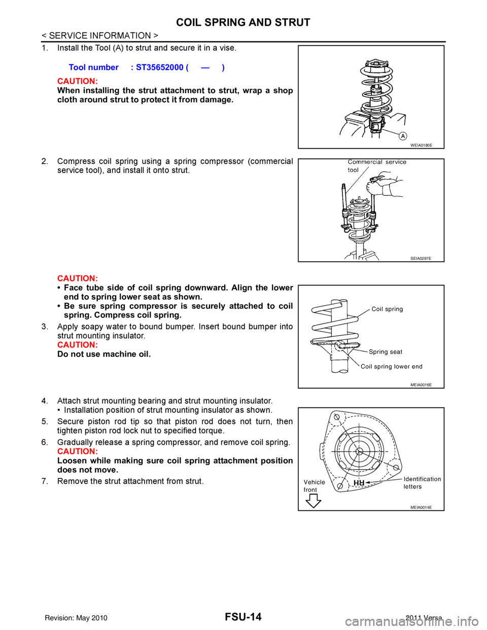
1. Install the Tool (A) to strut and secure it in a vise.CAUTION:
When installing the strut att achment to strut, wrap a shop
cloth around strut to protect it from damage.
2. Compress coil spring using a spring compressor (commercial service tool), and install it onto strut.
CAUTION:
• Face tube side of coil spri ng downward. Align the lower
end to spring lower seat as shown.
• Be sure spring compressor is securely attached to coil
spring. Compress coil spring.
3. Apply soapy water to bound bumper. Insert bound bumper into strut mounting insulator.
CAUTION:
Do not use machine oil.
4. Attach strut mounting bearing and strut mounting insulator. • Installation position of strut mounting insulator as shown.
5. Secure piston rod tip so that piston rod does not turn, then tighten piston rod lock nut to specified torque.
6. Gradually release a spring compressor, and remove coil spring. CAUTION:
Loosen while making sure co il spring attachment position
does not move.
7. Remove the strut attachment from strut. Tool number : ST35652000 ( — )
WEIA0180E
SEIA0297E
MEIA0016E
MEIA0014E
Revision: May 2010
2011 Versa
Page 2701 of 3787
FSU-16
< SERVICE INFORMATION >
STABILIZER BAR
STABILIZER BAR
Removal and InstallationINFOID:0000000005930906
REMOVAL
1. Separate intermediate shaft from steering gear pinion shaft. Refer to PS-13, "Removal and Installation".
2. Remove front tires using power tool.
3. Remove the nut on the lower side of stabilizer connecting rod using power tool, and then remove stabilizer connecting rod from stabilizer bar.
4. If necessary remove stabilize connecting rod upper nut using power tool. Separate stabilizer connecting rod and strut.
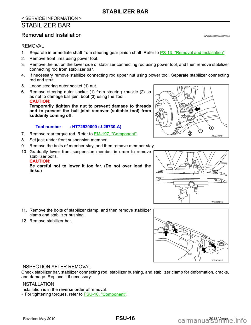
5. Loose steering outer socket (1) nut.
6. Remove steering outer socket (1) from steering knuckle (2) so as not to damage ball joint boot (3) using the Tool.
CAUTION:
Temporarily tighten the nut to prevent damage to threads
and to prevent the ball joint remover (suitable tool) from
suddenly coming off.
7. Remove rear torque rod. Refer to EM-197, "
Component".
8. Set jack under front suspension member.
9. Remove the bolts of member stay, and then remove member stay.
10. Gradually lower front suspension member in order to remove stabilizer bolts.
CAUTION:
Be careful not to lower it too far. (Do not over load the
links.)
11. Remove the bolts of stabilizer clamp, and then remove stabilizer clamp and stabilizer bushing.
12. Remove stabilizer bar.
INSPECTION AFTER REMOVAL
Check stabilizer bar, stabilizer connecting rod, stabilizer bushing, and stabilizer clamp for deformation, cracks,
and damage. Replace it if necessary.
INSTALLATION
Installation is in the reverse order of removal.
• For tightening torques, refer to FSU-10, "
Component".
Tool number : HT72520000 (J-25730-A)
SGIA1298E
WEIA0181E
WEIA0182E
Revision: May 2010
2011 Versa
Page 2705 of 3787
GI-1
GENERAL INFORMATION
C
DE
F
G H
I
J
K L
M B
GI
SECTION GI
N
O P
CONTENTS
GENERAL INFORMATION
SERVICE INFORMATION .. ..........................2
PRECAUTIONS .............................................. .....2
Description .......................................................... ......2
Precaution for Supplemental Restraint System
(SRS) "AIR BAG" and "SEAT BELT PRE-TEN-
SIONER" ...................................................................
2
Precaution Necessary for Steering Wheel Rota-
tion After Battery Disconnect ............................... ......
2
General Precaution ...................................................3
Precaution for Three Way Catalyst ...........................4
Precaution for Fuel (Unleaded Regular Gasoline
Recommended) .........................................................
4
Precaution for Multiport Fuel Injection System or
Engine Control System .............................................
5
Precaution for Hoses .................................................5
Precaution for Engine Oils ........................................6
Precaution for Air Conditioning .................................6
HOW TO USE THIS MANUAL ............................7
Description .......................................................... ......7
Terms ........................................................................7
Units ..........................................................................7
Contents ....................................................................7
Relation between Illustrations and Descriptions .......8
Component ................................................................8
How to Follow Trouble Diagnosis ..............................9
How to Read Wiring Diagram ..................................13
Abbreviations ...................................................... ....20
SERVICE INFORMATION FOR ELECTRICAL
INCIDENT ...........................................................
22
How to Check Terminal ...........................................22
How to Perform Efficient Diagnosis for an Electri-
cal Incident .......................................................... ....
25
Control Units and Electrical Parts ............................32
CONSULT-III CHECKING SYSTEM .................35
Description ...............................................................35
Function and System Application ............................35
CONSULT-III Data Link Connector (DLC) Circuit ....36
LIFTING POINT .................................................38
Special Service Tool ................................................38
Garage Jack and Safety Stand and 2-Pole Lift .......38
Board-On Lift ...........................................................39
TOW TRUCK TOWING .....................................40
Tow Truck Towing ...................................................40
Vehicle Recovery (Freeing a Stuck Vehicle) ...........40
TIGHTENING TORQUE OF STANDARD
BOLTS ...............................................................
41
Tightening Torque Table .........................................41
RECOMMENDED CHEMICAL PRODUCTS
AND SEALANTS ...............................................
42
Recommended Chemical Product and Sealant .......42
IDENTIFICATION INFORMATION ....................43
Model Variation ........................................................43
Dimensions ..............................................................46
Wheels & Tires ........................................................46
TERMINOLOGY ................................................47
SAE J1930 Terminology List ...................................47
Revision: May 2010 2011 Versa
Page 3238 of 3787
![NISSAN TIIDA 2011 Service Repair Manual TRANSAXLE ASSEMBLYMT-17
< SERVICE INFORMATION > [RS5F91R]
D
E
F
G H
I
J
K L
M A
B
MT
N
O P
TRANSAXLE ASSEMBLY
Exploded ViewINFOID:0000000005929672
Removal and InstallationINFOID:0000000005929673
CAUTI NISSAN TIIDA 2011 Service Repair Manual TRANSAXLE ASSEMBLYMT-17
< SERVICE INFORMATION > [RS5F91R]
D
E
F
G H
I
J
K L
M A
B
MT
N
O P
TRANSAXLE ASSEMBLY
Exploded ViewINFOID:0000000005929672
Removal and InstallationINFOID:0000000005929673
CAUTI](/manual-img/5/57396/w960_57396-3237.png)
TRANSAXLE ASSEMBLYMT-17
< SERVICE INFORMATION > [RS5F91R]
D
E
F
G H
I
J
K L
M A
B
MT
N
O P
TRANSAXLE ASSEMBLY
Exploded ViewINFOID:0000000005929672
Removal and InstallationINFOID:0000000005929673
CAUTION:
If transaxle assembly is removed from the vehicle , always replace CSC (Concentric Slave Cylinder).
Return CSC insert to original pos ition to remove transaxle assembly. Du st on clutch disc sliding parts
may damage seal of CSC and may cau se clutch fluid leakage. Refer to CL-13, "
Removal and Installa-
tion".
REMOVAL
1. Drain clutch fluid and remove clutch tube from CSC. Refer to CL-13, "Removal and Installation".
CAUTION:
Do not depress clutch pedal during removal procedure.
2. Remove the engine and transaxle as an assembly from the vehicle. Refer t\
o EM-82, "
Removal and Instal-
lation".
3. Remove the transaxle to engine and engine to transaxle bolts.
4. Separate the transaxle assembly from the engine.
INSTALLATION
Installation is in the reverse order of removal.
1. LH engine mount bracket (transaxle side) 2. Transaxle assembly 3. Rear engine mount bracket
4. Washer 5. Rear torque rod Front
: Refer to installation.
PCIB1514E
Revision: May 2010
2011 Versa