2011 NISSAN TIIDA Co-4
[x] Cancel search: Co-4Page 2521 of 3787
![NISSAN TIIDA 2011 Service Repair Manual NOISE, VIBRATION AND HARSHNESS (NVH) TROUBLESHOOTINGEM-131
< SERVICE INFORMATION > [MR18DE]
C
D
E
F
G H
I
J
K L
M A
EM
NP
OUse the Chart Below to Help You
Find the Cause of the SymptomINFOID:00000000 NISSAN TIIDA 2011 Service Repair Manual NOISE, VIBRATION AND HARSHNESS (NVH) TROUBLESHOOTINGEM-131
< SERVICE INFORMATION > [MR18DE]
C
D
E
F
G H
I
J
K L
M A
EM
NP
OUse the Chart Below to Help You
Find the Cause of the SymptomINFOID:00000000](/manual-img/5/57396/w960_57396-2520.png)
NOISE, VIBRATION AND HARSHNESS (NVH) TROUBLESHOOTINGEM-131
< SERVICE INFORMATION > [MR18DE]
C
D
E
F
G H
I
J
K L
M A
EM
NP
OUse the Chart Below to Help You
Find the Cause of the SymptomINFOID:0000000005930996
1. Locate the area where noise occurs.
2. Confirm the type of noise.
3. Specify the operating condition of engine.
4. Check specified noise source.
If necessary, repair or replace these parts.
A: Closely related B: Related C: Sometimes related —: Not relatedD. Drive belt
E. Crankshaft pulleyF. A/C compressor
G. Water pump H. GeneratorI. Tension pulley
J. Valve mechanism K. Valves
Location of noise Type of
noise Operating condition of engine
Source of noise Check item
Refer-
ence page
Before
warm-
up After
warm-
up When
start-
ing When
idling When
racing While
driving
Top of en-
gine
Rocker
cover
Cylinder
head Ticking or
clicking
CA—AB—
Tappet
noiseValve clearance
EM-230
Rattle C A — A B C Camshaft
bearing
noiseCamshaft journal oil
clearance
Camshaft runout
EM-170EM-170
Crank-
shaft pul-
ley
Cylinder
block
(Side of
engine)
Oil panSlap or
knock
—A—BB—
Piston pin
noisePiston to piston pin oil
clearance
Connecting rod bushing
oil clearance
EM-219
EM-219
Slap or
rap
A——BBA
Piston
slap noisePiston to cylinder bore
clearance
Piston ring side clear-
ance
Piston ring end gap
Connecting rod bend
and torsion EM-219EM-219
EM-219
EM-219
Knock A B C B B B
Connect-
ing rod
bearing
noiseConnecting rod bushing
oil clearance
Connecting rod bearing
oil clearance
EM-219EM-219
Knock A B — A B C
Main bear-
ing noiseMain bearing oil clear-
ance
Crankshaft runout EM-219EM-219
Front of
engine
Front cov-
erTapping or
ticking
AA—BBB Timing
chain and
chain ten-
sioner
noiseTiming chain cracks
and wear
Timing chain tensioner
operation
EM-160
Front of
engineSqueak-
ing or fizz-
ing
AB—B—C Drive belt
(Sticking
or slip-
ping)Drive belt deflection
EM-132
CreakingA B ABAB Drive belt
(Slipping)Idler pulley bearing op-
eration
Squall
Creak AB—BAB Water
pump
noiseWater pump operation
CO-45
Revision: May 2010 2011 Versa
Page 2550 of 3787
![NISSAN TIIDA 2011 Service Repair Manual EM-160
< SERVICE INFORMATION >[MR18DE]
TIMING CHAIN
Removal and Installation
INFOID:0000000005931017
CAUTION:
The rotating direction in dicated in the text indicates all directions seen from the engin NISSAN TIIDA 2011 Service Repair Manual EM-160
< SERVICE INFORMATION >[MR18DE]
TIMING CHAIN
Removal and Installation
INFOID:0000000005931017
CAUTION:
The rotating direction in dicated in the text indicates all directions seen from the engin](/manual-img/5/57396/w960_57396-2549.png)
EM-160
< SERVICE INFORMATION >[MR18DE]
TIMING CHAIN
Removal and Installation
INFOID:0000000005931017
CAUTION:
The rotating direction in dicated in the text indicates all directions seen from the engine front.
REMOVAL
1. Disconnect the battery negative terminal. Refer to SC-7, "Removal and Installation".
2. Drain engine oil. Refer to LU-18, "
Changing Engine Oil".
CAUTION:
Perform this step when engine is cold.
3. Partially drain engine coolant from the radiator. Refer to CO-36, "
Changing Engine Coolant".
4. Remove front RH wheel. Refer to WT-7, "
Adjustment".
5. Remove front fender protector (RH). Refer to EI-26, "
Removal and Installation".
6. Remove the following parts. • Rocker cover: Refer to EM-151, "
Component".
• Drive belt: Refer to EM-132, "
Removal and Installation".
• Water pump pulley: Refer to CO-45, "
Component".
• Ground cable (between engine bracket (RH) and radiator core support)
7. Support the bottom surface of engine using a trans mission jack, and then remove the engine bracket and
insulator (RH). Refer to EM-197, "
Component".
8. Set No. 1 cylinder at TDC on its compression stroke with the following procedure:
a. Rotate crankshaft pulley (1) clockwise and align TDC mark (no paint) (B) to timing indicator (A) on front cover.
b. At the same time, make sure that the cam noses of the No.1 cyl- inder are located ( ) as shown.
• If not, rotate crankshaft pulley one revolution (360 degrees)and align as shown.
16. Oil pump drive chain 17. Camshaft sprocket (INT) 18. Timing chain tension guide
19. O-ring 20. Chain tensioner (for oil pump)
A. Refer to EM-160
B. Refer to EM-170
C : White paint mark (Not use for service)
PBIC3960E
1 : Camshaft (INT)
2 : Camshaft (EXH)
: Engine front
PBIC3359J
Revision: May 2010 2011 Versa
Page 2588 of 3787
![NISSAN TIIDA 2011 Service Repair Manual EM-198
< SERVICE INFORMATION >[MR18DE]
ENGINE ASSEMBLY
• Use either 2-pole lift type or separate type lift as
best you can. If board-on type is used for unavoid-
able reasons, support at the rear a NISSAN TIIDA 2011 Service Repair Manual EM-198
< SERVICE INFORMATION >[MR18DE]
ENGINE ASSEMBLY
• Use either 2-pole lift type or separate type lift as
best you can. If board-on type is used for unavoid-
able reasons, support at the rear a](/manual-img/5/57396/w960_57396-2587.png)
EM-198
< SERVICE INFORMATION >[MR18DE]
ENGINE ASSEMBLY
• Use either 2-pole lift type or separate type lift as
best you can. If board-on type is used for unavoid-
able reasons, support at the rear axle jacking point with a transmission jack or similar tool before
starting work, in preparation for the backward shift of center of gravity.
• For supporting points for lifting and jacking point at rear axle, refer to GI-38, "
Garage Jack and
Safety Stand and 2-Pole Lift".
REMOVAL
Remove the engine and the transaxle assembly from t he vehicle downward. Separate the engine and the tran-
saxle.
1. Remove engine under cover. Refer to EI-15, "
Removal and Installation".
2. Drain engine coolant from radiator. Refer to CO-36, "
Changing Engine Coolant".
CAUTION:
• Perform this step when the engine is cold.
• Do not spill engine coolant on drive belt.
3. Drain clutch fluid (M/T models). Refer to CL-9, "
Air Bleeding Procedure".
4. Remove front fender protector (RH and LH). Refer to EI-26
.
5. Remove exhaust front tube. Refer to EX-10
.
6. Remove drive shafts (LH and RH) from steering knuckle. Refer to FA X - 9
.
7. Remove transaxle joint bolts which pierce at oil pan (upper) lower rear side. Refer to AT-233
(A/T models),
CVT-180, "
Removal and Installation" (CVT models) or MT-61, "Removal and Installation" (M/T models).
8. Remove rear torque rod (1). NOTE:
A/T model shown CVT and M/T models similar.
9. Remove hood assembly. Refer to BL-13
.
10. Remove cowl top cover and cowl top extension assembly. Refer to EI-24
.
11. Release fuel pressure. Refer to EC-582, "
Fuel Pressure Check".
12. Remove battery and battery tray. Refer to SC-5
.
13. Remove drive belt; Refer to EM-132, "
Component".
14. Remove engine room cover.
15. Remove air duct and air cleaner case assembly. Refer to EM-135
.
16. Remove cooling fan assembly. Refer to CO-44, "
Removal and Installation".
17. Remove radiator hose (upper and lower). Refer to CO-40
.
18. Disconnect A/T fluid cooler hoses or CVT water hoses. Refer to CO-40, "
Component" (A/T) or CVT-175,
"WATER HOSE : Exploded View" (CVT).
NOTE:
Cap or plug opening(s) to prevent fluid from spilling.
19. Disconnect all connections of engine harness around the engine mounting insulator (LH), and then tem- porarily secure the engine harness into the engine side.
CAUTION:
Protect connectors using a resin bag to protect against foreign materials during the operation.
20. Disconnect fuel feed hose at engine side. Refer to EM-154, "
Component".
NOTE:
Cap or plug opening(s) to revent fluid from spilling.
21. Disconnect heater hoses. Refer to CO-50, "
Component".
NOTE:
Cap or plug opening(s) to revent fluid from spilling.
LBIA0460E
Revision: May 2010 2011 Versa
Page 2593 of 3787
![NISSAN TIIDA 2011 Service Repair Manual CYLINDER BLOCKEM-203
< SERVICE INFORMATION > [MR18DE]
C
D
E
F
G H
I
J
K L
M A
EM
NP
O
Disassembly and AssemblyINFOID:0000000005931033
DISASSEMBLY
1. Remove engine and transaxle assembly from vehicle, NISSAN TIIDA 2011 Service Repair Manual CYLINDER BLOCKEM-203
< SERVICE INFORMATION > [MR18DE]
C
D
E
F
G H
I
J
K L
M A
EM
NP
O
Disassembly and AssemblyINFOID:0000000005931033
DISASSEMBLY
1. Remove engine and transaxle assembly from vehicle,](/manual-img/5/57396/w960_57396-2592.png)
CYLINDER BLOCKEM-203
< SERVICE INFORMATION > [MR18DE]
C
D
E
F
G H
I
J
K L
M A
EM
NP
O
Disassembly and AssemblyINFOID:0000000005931033
DISASSEMBLY
1. Remove engine and transaxle assembly from vehicle, separate transaxle from engine. Refer to
EM-197.
2. Install engine to engine stand as follows;
a. Remove flywheel (M/T models) or drive plate (1) (A/T or CVT models).
• Secure flywheel (M/T models) or drive plate (A/T or CVT mod-els) using Tool (A), and remove bolts.
CAUTION:
Be careful not to damage or scratch drive plate (A/T or CVT
models) and contact surface for clutch disc of flywheel (M/T
models).
NOTE:
Figure shows drive plate (1) (A/T or CVT models)
b. Lift the engine with a hoist to install it onto widely use engine stand. CAUTION:
• Use the engine stand that has a load capacity [approximately 135 kg (298 lb) or more] large
enough for supporting the engine weight.
• If the load capacity of stand is not adequate, remove the following parts beforehand to reduce the poten-
tial risk of overturning stand.
- Exhaust manifold; Refer to EM-141
.
- Rocker cover; Refer to EM-151
.
NOTE:
The figure shows an example of widely used engine stand (A)
that can support mating surface of transaxle with flywheel (M/T
models) or drive plate (A/T or CVT models) removed.
CAUTION:
Before removing the hanging chains, make sure the engine
stand is stable and there is no risk of overturning.
3. Remove oil pan (upper and lower). Refer to EM-144
.
4. Remove cylinder head. Refer to EM-186
.
5. Remove thermostat housing. Refer to CO-47
.
6. Remove knock sensor. CAUTION:
Carefully handle knock sensor avoiding shocks.
7. Remove crankshaft position sensor (POS) cover and crankshaft position sensor (POS).
7. Oil pressure switch 8. Top ring 9. Second ring
10. Oil ring 11. Snap ring 12. Piston
13. Piston pin 14. Connecting rod 15. Thrust bearing
16. Connecting rod bearing upper 17. Main bearing upper 18. Crankshaft key
19. Main bearing lower 20. Connecting rod bearing lower 21. Connecting rod bearing cap
22. Connecting rod bolt 23. Main bearing cap 24. Main bearing cap bolt
25. Crankshaft 26. Pilot converter (A/T or CVT models) 27. Signal plate
28. Rear oil seal 29. Drive plate (A/T or CVT models) 30. Reinforcement plate (A/T or CVT
models)
31. Flywheel (M/T models) 32. Block heater (Canada only) A. Refer to EM-203
Tool number : KV 11105210 (J-44716)
PBIC3226J
PBIC3227J
Revision: May 2010 2011 Versa
Page 3198 of 3787

ENGINE MAINTENANCE (MR18DE)MA-27
< SERVICE INFORMATION >
C
DE
F
G H
I
J
K
M A
B
MA
N
O P
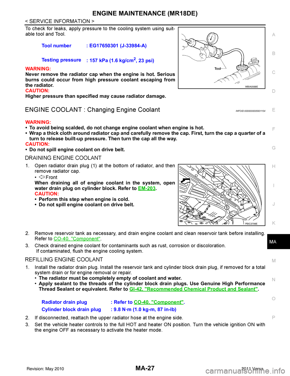
To check for leaks, apply pressure to the cooling system using suit-
able tool and Tool.
WARNING:
Never remove the radiator cap wh en the engine is hot. Serious
burns could occur from high pressure coolant escaping from
the radiator.
CAUTION:
Higher pressure than specified may cause radiator damage.
ENGINE COOLANT : Chang ing Engine CoolantINFOID:0000000005931154
WARNING:
• To avoid being scalded, do not change engine coolant when engine is hot.
• Wrap a thick cloth around radiator cap and carefully remove the cap. First, turn the cap a quarter of a
turn to release built-up pressure. Then turn the cap all the way.
CAUTION:
• Do not spill engine coolant on drive belt.
DRAINING ENGINE COOLANT
1. Open radiator drain plug (1) at the bottom of radiator, and then remove radiator cap.
• Front
When draining all of engine coolant in the system, open
water drain plug on cylinder block. Refer to EM-203
.
CAUTION:
• Perform this step when engine is cold.
• Do not spill engine coolant on drive belt.
2. Remove reservoir tank as necessary, and drain engi ne coolant and clean reservoir tank before installing.
Refer to CO-40, "
Component".
3. Check drained engine coolant for contaminants such as rust, corrosion or discoloration. If contaminated, flush the engine cooling system.
REFILLING ENGINE COOLANT
1. Install the radiator drain plug. Install the reservoir tank and cylinder block drain plug, if removed for a total
system drain or for engine removal or repair.
• The radiator must be completely empty of coolant and water.
• Apply sealant to the threads of the cylinder blo ck drain plugs. Use Genuine High Performance
Thread Sealant or equivalent. Refer to GI-42, "
Recommended Chemical Product and Sealant".
2. If disconnected, reattach the upper radiator hose at the engine side.
3. Set the vehicle heater controls to the full HOT and heat er ON position. Turn the vehicle ignition ON with
the engine OFF as necessary to activate the heater mode. Tool number : EG17650301 (J-33984-A)
Testing pressure
: 157 kPa (1.6 kg/cm
2, 23 psi)
WBIA0568E
PBIC3799E
Radiator drain plug : Refer to CO-40, "Component".
Cylinder block drain plug : 9.8 N·m (1.0 kg-m, 87 in-lb)
Revision: May 2010 2011 Versa
Page 3199 of 3787

MA-28
< SERVICE INFORMATION >
ENGINE MAINTENANCE (MR18DE)
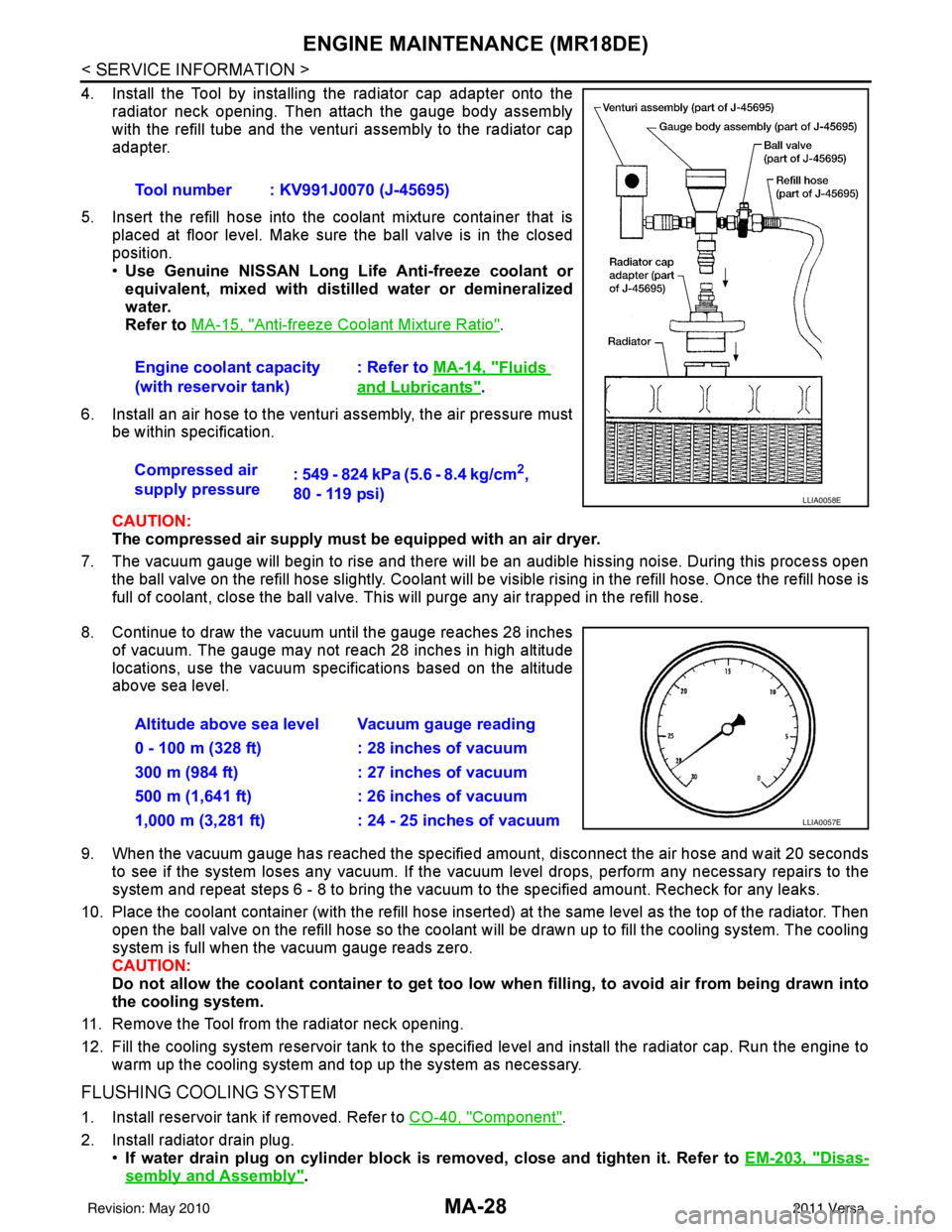
4. Install the Tool by installing the radiator cap adapter onto theradiator neck opening. Then attach the gauge body assembly
with the refill tube and the venturi assembly to the radiator cap
adapter.
5. Insert the refill hose into the coolant mixture container that is placed at floor level. Make sure the ball valve is in the closed
position.
•Use Genuine NISSAN Long Life Anti-freeze coolant or
equivalent, mixed with distil led water or demineralized
water.
Refer to MA-15, "
Anti-freeze Coolant Mixture Ratio".
6. Install an air hose to the venturi assembly, the air pressure must be within specification.
CAUTION:
The compressed air supply must be equipped with an air dryer.
7. The vacuum gauge will begin to rise and there will be an audible hissing noise. During this process open the ball valve on the refill hose slightly. Coolant will be vi sible rising in the refill hose. Once the refill hose is
full of coolant, close the ball valve. This will purge any air trapped in the refill hose.
8. Continue to draw the vacuum until the gauge reaches 28 inches of vacuum. The gauge may not reach 28 inches in high altitude
locations, use the vacuum specifications based on the altitude
above sea level.
9. When the vacuum gauge has reached the specifi ed amount, disconnect the air hose and wait 20 seconds
to see if the system loses any vacuum. If the vacuum level drops, perform any necessary repairs to the
system and repeat steps 6 - 8 to bring the vacuum to the specified amount. Recheck for any leaks.
10. Place the coolant container (with the refill hose insert ed) at the same level as the top of the radiator. Then
open the ball valve on the refill hose so the coolant will be drawn up to fill the cooling system. The cooling
system is full when the vacuum gauge reads zero.
CAUTION:
Do not allow the coolant container to get too low when filling, to avoid air from being drawn into
the cooling system.
11. Remove the Tool from the radiator neck opening.
12. Fill the cooling system reservoir tank to the specified level and install the radiator cap. Run the engine to warm up the cooling system and t op up the system as necessary.
FLUSHING COOLING SYSTEM
1. Install reservoir tank if removed. Refer to CO-40, "Component".
2. Install radiator drain plug. •If water drain plug on cylinder block is removed, close and tighten it. Refer to EM-203, "
Disas-
sembly and Assembly".
Tool number : KV991J0070 (J-45695)
Engine coolant capacity
(with reservoir tank)
: Refer to
MA-14, "
Fluids
and Lubricants".
Compressed air
supply pressure : 549 - 824 kPa (5.6 - 8.4 kg/cm
2,
80 - 119 psi)
LLIA0058E
Altitude above sea level Vacuum gauge reading
0 - 100 m (328 ft) : 28 inches of vacuum
300 m (984 ft) : 27 inches of vacuum
500 m (1,641 ft) : 26 inches of vacuum
1,000 m (3,281 ft) : 24 - 25 inches of vacuum
LLIA0057E
Revision: May 2010 2011 Versa
Page 3200 of 3787

ENGINE MAINTENANCE (MR18DE)MA-29
< SERVICE INFORMATION >
C
DE
F
G H
I
J
K
M A
B
MA
N
O P
CAUTION:
Be sure to clean radiator drain plug and install with new O-ring. Refer to CO-40, "
Component".
3. Fill radiator and reservoir tank with water and reinstall radiator cap.
4. Run engine and warm it up to normal operating temperature.
5. Rev engine two or three times under no-load.
6. Stop engine and wait until it cools down.
7. Drain water from the cooling system.
8. Repeat steps 1 through 7 until clear water begins to drain from radiator.
FUEL LINES
FUEL LINES : Checking Fuel LineINFOID:0000000005931155
Inspect fuel lines, fuel filler cap and fuel tank for improper attach-
ment, leaks, cracks, damage, loos e connections, chafing or deterio-
ration.
If necessary, repair or replace damaged parts.
AIR CLEANER FILTER
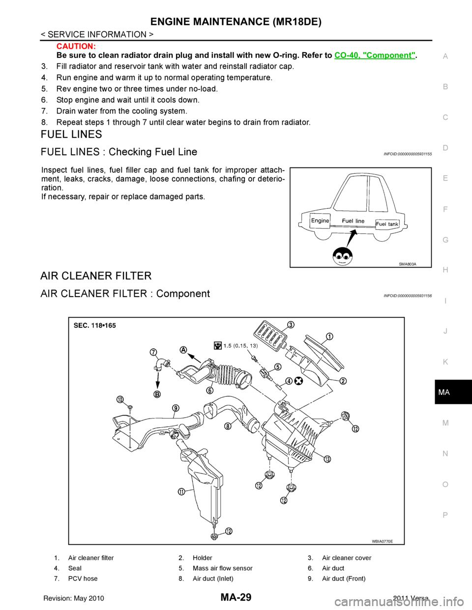
AIR CLEANER FILTER : ComponentINFOID:0000000005931156
SMA803A
1. Air cleaner filter 2. Holder 3. Air cleaner cover
4. Seal 5. Mass air flow sensor 6. Air duct
7. PCV hose 8. Air duct (Inlet) 9. Air duct (Front)
WBIA0770E
Revision: May 2010 2011 Versa
Page 3604 of 3787

SC-26
< SERVICE INFORMATION >
CHARGING SYSTEM
REMOVAL
1. Disconnect the battery negative terminal. Refer to SC-7, "Removal and Installation".
2. Remove drive belt. Refer to EM-14, "
Removal and Installation" (HR16DE), EM-132, "Removal and Instal-
lation" (MR18DE).
3. Remove radiator reservoir tank. Refer to CO-16, "
Removal and Installation" (HR16DE), CO-40, "Removal
and Installation" (MR18DE).
4. Disconnect generator connector.
5. Remove “B” terminal nut.
6. Remove generator bolts.
7. Remove generator assembly from the vehicle.
GENERATOR PULLEY INSPECTION
• Check that the generator pulley does not rattle.
• Check that the generator pulley nut is properly tightened.
INSTALLATION
Installation is in the reverse order of removal.
CAUTION:
Be sure to tighten “B” terminal nut carefully.
1. Generator bracket bolt 2. Generator bracket3. Generator bolt
4. Generator 5. Generator "B" terminal harness 6. "B" terminal nut
7. Generator connector
Generator pulley nut : 118 N·m (12.0 kg-m, 87 ft-lb)
Revision: May 2010 2011 Versa