2011 NISSAN TIIDA light
[x] Cancel search: lightPage 318 of 3787
REPAIR FOR COMPONENT PARTSAT-301
< SERVICE INFORMATION >
DE
F
G H
I
J
K L
M A
B
AT
N
O P
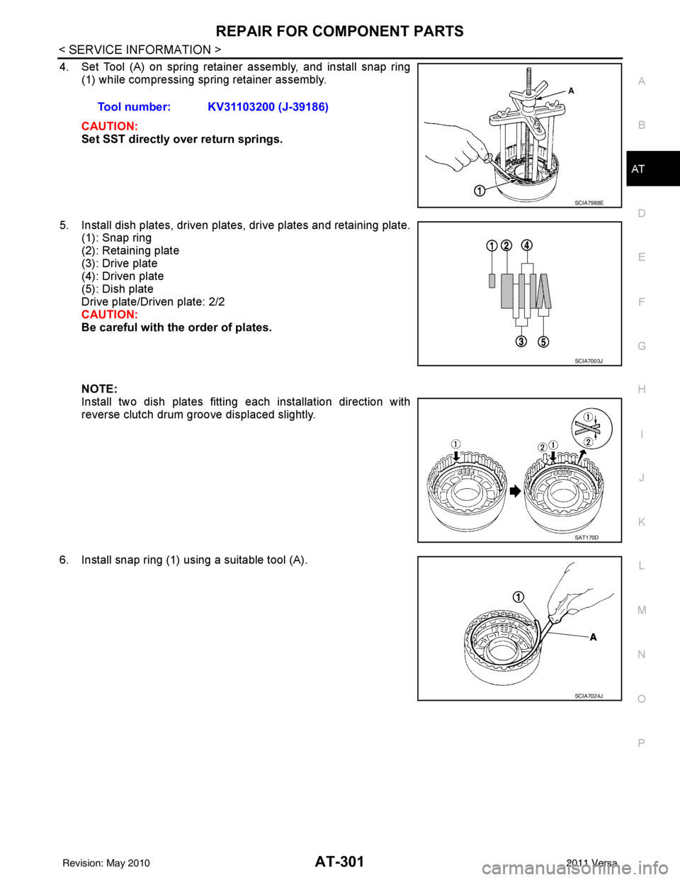
4. Set Tool (A) on spring retainer assembly, and install snap ring (1) while compressing spring retainer assembly.
CAUTION:
Set SST directly over return springs.
5. Install dish plates, driven plates, drive plates and retaining plate. (1): Snap ring
(2): Retaining plate
(3): Drive plate
(4): Driven plate
(5): Dish plate
Drive plate/Driven plate: 2/2
CAUTION:
Be careful with the order of plates.
NOTE:
Install two dish plates fitting each installation direction with
reverse clutch drum groove displaced slightly.
6. Install snap ring (1) using a suitable tool (A). Tool number: KV31103200 (J-39186)
SCIA7988E
SCIA7003J
SAT170D
SCIA7024J
Revision: May 2010
2011 Versa
Page 335 of 3787
AT-318
< SERVICE INFORMATION >
REPAIR FOR COMPONENT PARTS
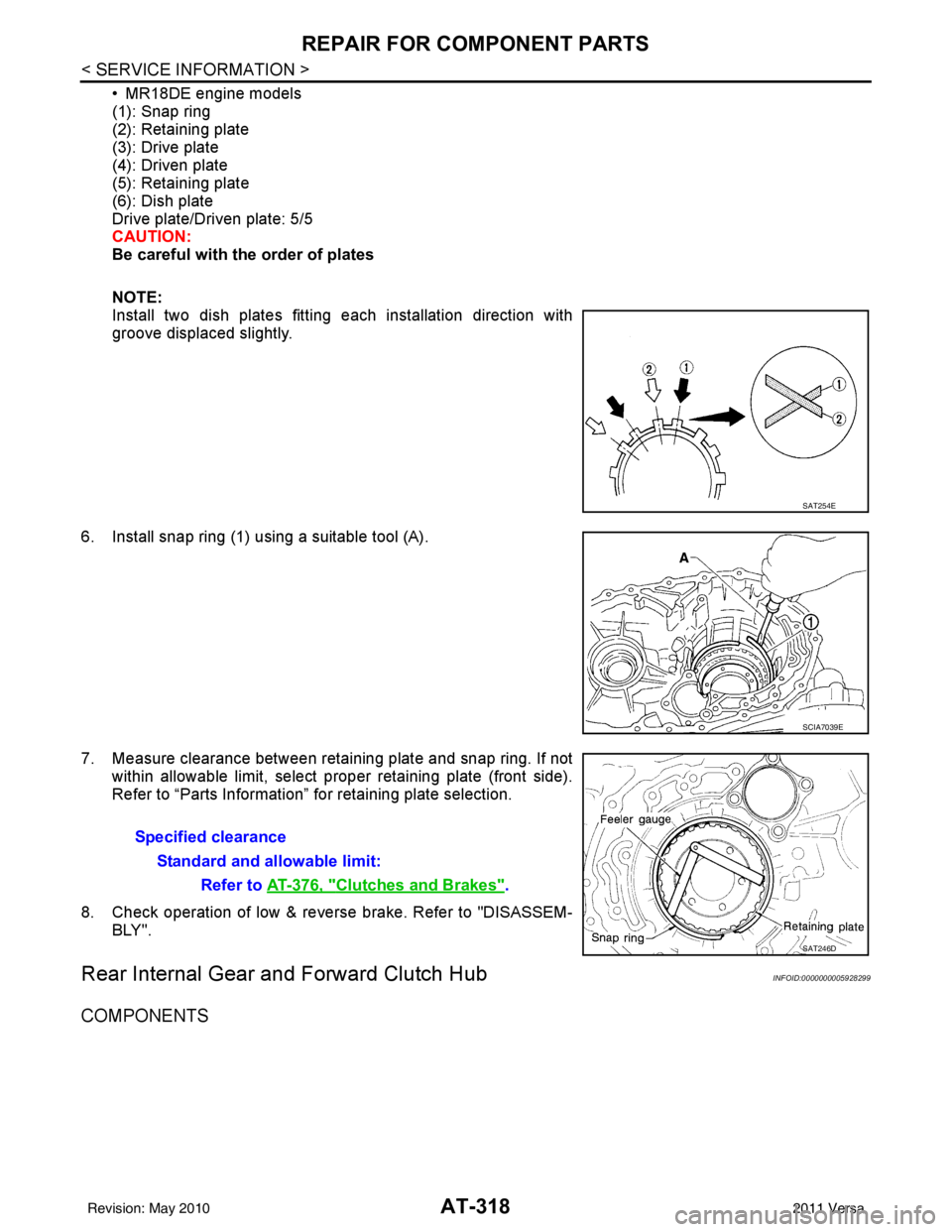
• MR18DE engine models
(1): Snap ring
(2): Retaining plate
(3): Drive plate
(4): Driven plate
(5): Retaining plate
(6): Dish plate
Drive plate/Driven plate: 5/5
CAUTION:
Be careful with the order of plates
NOTE:
Install two dish plates fitting each installation direction with
groove displaced slightly.
6. Install snap ring (1) using a suitable tool (A).
7. Measure clearance between retaining plate and snap ring. If not within allowable limit, select proper retaining plate (front side).
Refer to “Parts Information” for retaining plate selection.
8. Check operation of low & revers e brake. Refer to "DISASSEM-
BLY".
Rear Internal Gear and Forward Clutch HubINFOID:0000000005928299
COMPONENTS
SAT254E
SCIA7039E
Specified clearance
Standard and allowable limit: Refer to AT-376, "
Clutches and Brakes".
SAT246D
Revision: May 2010 2011 Versa
Page 368 of 3787
ASSEMBLYAT-351
< SERVICE INFORMATION >
DE
F
G H
I
J
K L
M A
B
AT
N
O P
m. Reinstall converter housing on transaxle case and ti ghten converter housing bolts to the specified torque.
Refer to AT-237, "
Component".
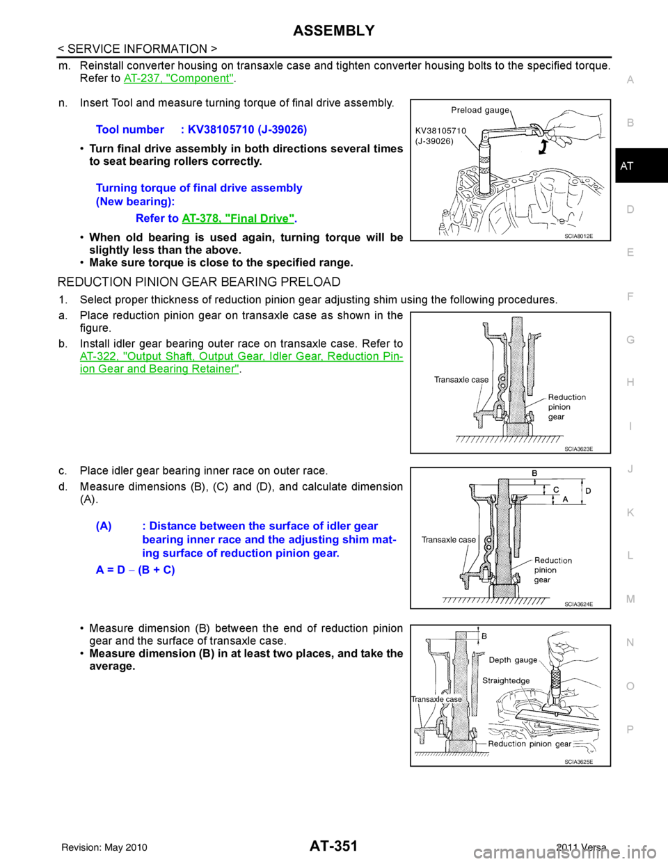
n. Insert Tool and measure turning torque of final drive assembly.
•Turn final drive assembly in both directions several times
to seat bearing rollers correctly.
• When old bearing is used ag ain, turning torque will be
slightly less than the above.
• Make sure torque is close to the specified range.
REDUCTION PINION GEAR BEARING PRELOAD
1. Select proper thickness of reduction pinion gear adjusting shim using the following procedures.
a. Place reduction pinion gear on transaxle case as shown in the figure.
b. Install idler gear bearing outer race on transaxle case. Refer to AT-322, "
Output Shaft, Output Gear, Idler Gear, Reduction Pin-
ion Gear and Bearing Retainer".
c. Place idler gear bearing inner race on outer race.
d. Measure dimensions (B), (C) and (D), and calculate dimension (A).
• Measure dimension (B) between the end of reduction pinion
gear and the surface of transaxle case.
• Measure dimension (B) in at least two places, and take the
average.Tool number : KV38105710 (J-39026)
Turning torque of final drive assembly
(New bearing):
Refer to AT-378, "
Final Drive".
SCIA8012E
SCIA3623E
(A) : Distance between the surface of idler gear
bearing inner race and th e adjusting shim mat-
ing surface of reduction pinion gear.
A = D − (B + C)
SCIA3624E
SCIA3625E
Revision: May 2010 2011 Versa
Page 372 of 3787
ASSEMBLYAT-355
< SERVICE INFORMATION >
DE
F
G H
I
J
K L
M A
B
AT
N
O P
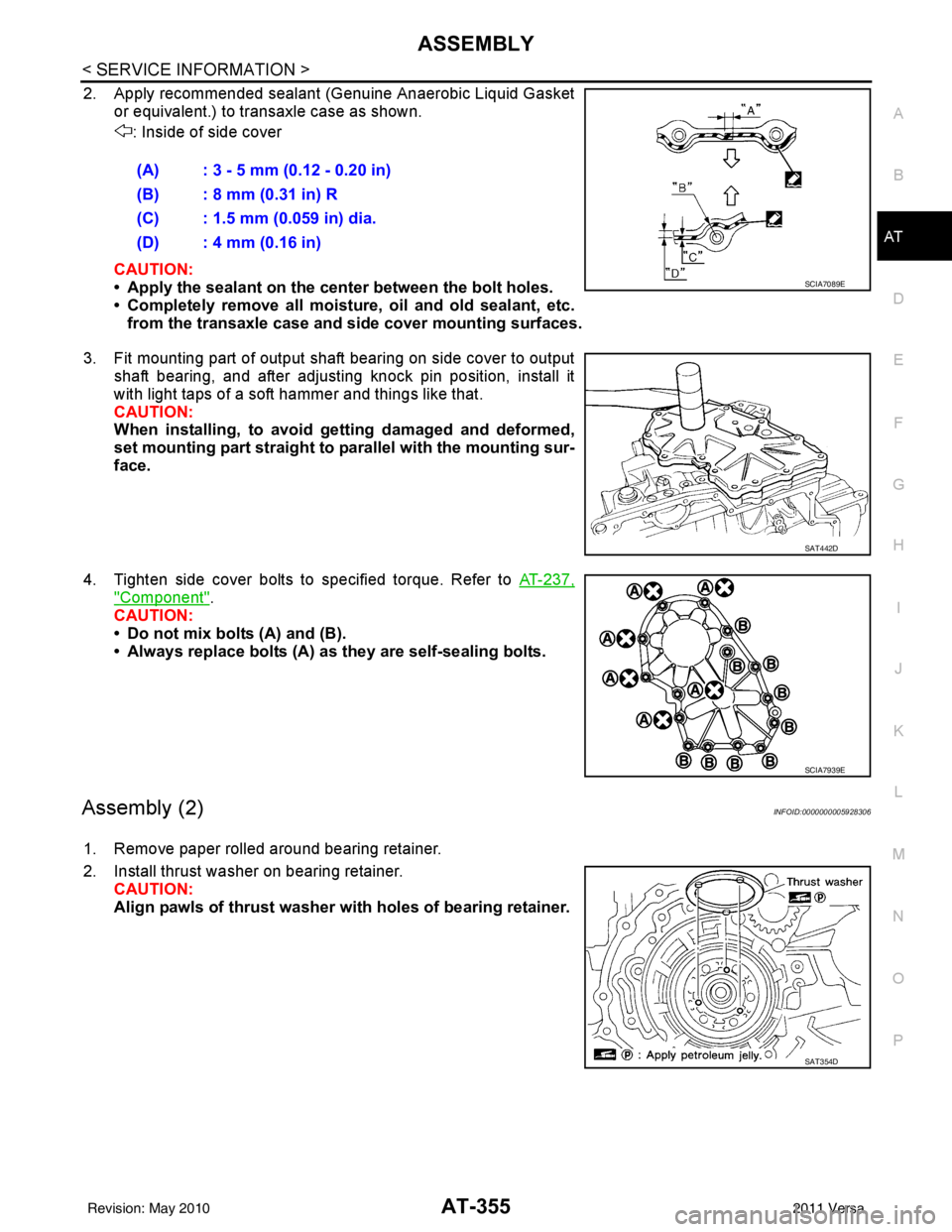
2. Apply recommended sealant (Genuine Anaerobic Liquid Gasket or equivalent.) to transaxle case as shown.
: Inside of side cover
CAUTION:
• Apply the sealant on the center between the bolt holes.
• Completely remove all moisture, oil and old sealant, etc. from the transaxle case and side cover mounting surfaces.
3. Fit mounting part of output shaft bearing on side cover to output shaft bearing, and after adjusting knock pin position, install it
with light taps of a soft hammer and things like that.
CAUTION:
When installing, to avoid getting damaged and deformed,
set mounting part straight to parallel with the mounting sur-
face.
4. Tighten side cover bolts to specified torque. Refer to AT-237,
"Component".
CAUTION:
• Do not mix bolts (A) and (B).
• Always replace bolts (A) as they are self-sealing bolts.
Assembly (2)INFOID:0000000005928306
1. Remove paper rolled around bearing retainer.
2. Install thrust washer on bearing retainer. CAUTION:
Align pawls of thrust washer with holes of bearing retainer.(A) : 3 - 5 mm (0.12 - 0.20 in)
(B) : 8 mm (0.31 in) R
(C) : 1.5 mm (0.059 in) dia.
(D) : 4 mm (0.16 in)
SCIA7089E
SAT442D
SCIA7939E
SAT354D
Revision: May 2010
2011 Versa
Page 418 of 3787
![NISSAN TIIDA 2011 Service Repair Manual AUDIOAV-21
< SERVICE INFORMATION > [AUDIO WITHOUT NAVIGATION]
C
D
E
F
G H
I
J
L
M A
B
AV
N
O P
NOTE:
Noise resulting from variations in field strength, such as fading noise and multi-path noise, or e](/manual-img/5/57396/w960_57396-417.png "NISSAN TIIDA 2011 Service Repair Manual AUDIOAV-21
< SERVICE INFORMATION > [AUDIO WITHOUT NAVIGATION]
C
D
E
F
G H
I
J
L
M A
B
AV
N
O P
NOTE:
Noise resulting from variations in field strength, such as fading noise and multi-path noise, or e")
AUDIOAV-21
< SERVICE INFORMATION > [AUDIO WITHOUT NAVIGATION]
C
D
E
F
G H
I
J
L
M A
B
AV
N
O P
NOTE:
Noise resulting from variations in field strength, such as fading noise and multi-path noise, or external noise
from trains and other sources. It is not a malfunction.
• Fading noise: This noise occurs because of variations in the field strength in a narrow range due to moun-
tains or buildings blocking the signal.
• Multi-path noise: This noise results from the waves sent directly from the broadcast station arriving at the antenna at a different time from the waves t hat reflect off of mountains or buildings.
Noise InspectionINFOID:0000000005931285
The vehicle itself can be a source of noise if noise prevention parts or electrical equipment is malfunctioning.
Check if noise is caused and/or changed by engine speed, ignition switch turned to each position, and opera-
tion of each piece of electrical equipment, and determine the cause.
NOTE:
The source of the noise can be found easily by listening to the noise while removing the fuses of electrical
components, one by one.
TYPE OF NOISE AND POSSIBLE CAUSE
No sound can be heard from one or several speakers. • Open or short in audio signal circuit between audio unit and front
speaker. Refer to AV- 2 4 , "
Sound Is Not Heard from Front Door
Speaker (Base System)" or AV- 2 6 , "Sound Is Not Heard from
Front Door Speaker or Tweeter (Premium System)" .
• Front speaker. Refer to AV- 2 4 , "
Sound Is Not Heard from Front
Door Speaker (Base System)" or AV- 2 6 , "Sound Is Not Heard
from Front Door Speaker or Tweeter (Premium System)" .
• Open or short in audio signal circuit between audio unit and rear
speaker. Refer to AV- 2 5 , "
Sound Is Not Heard from Rear Door
Speaker (Base System)" or AV- 2 7 , "Sound Is Not Heard from
Rear Door Speaker (Premium System)" .
• Rear speaker. Refer to AV- 2 5 , "
Sound Is Not Heard from Rear
Door Speaker (Base System)" or AV- 2 7 , "Sound Is Not Heard
from Rear Door Speaker (Premium System)" .
• Tweeter (mid level and premium system) AV- 2 6 , "
Sound Is Not
Heard from Front Door Speaker or Tweeter (Premium System)"
or AV- 2 7 , "
Sound Is Not Heard from Rear Door Speaker (Premi-
um System)" .
• Audio unit. Refer to AV- 2 9 , "
Removal and Installation" .
No sound can be heard from radio or noise is heard. • Antenna feeder. Refer to
AV- 3 3 , "
Location of Antenna" .
• Antenna. Refer to AV- 3 3 , "
Location of Antenna" .
• Audio unit. Refer to AV- 2 9 , "
Removal and Installation" .
Symptom
Check item
Occurrence condition Possible cause
Occurs only when engine is ON. A continuous growling noise occurs. The speed of
the noise varies with changes in the engine speed.
Ignition components
A whistling noise occurs while the engine speed is
high. A booming noise occurs while the engine is
running and the lighting switch is ON. Generator
Noise only occurs when various
electrical components are oper-
ating. A cracking or snapping sound occurs with the op-
eration of various switches.
Relay malfunction, radio malfunction
The noise occurs when various motors are operat-
ing. • Motor case ground
•Motor
The noise occurs constantly, not just under certain conditions. • Rear defogger coil malfunction
• Open circuit in printed heater
A cracking or snapping sound occurs while the vehicle is being driven, especially when
it is vibrating excessively. • Ground wire of body parts.
• Ground due to improper part installation
• Wiring connections or a short circuit
Revision: May 2010
2011 Versa
Page 463 of 3787
![NISSAN TIIDA 2011 Service Repair Manual AV-66
< SERVICE INFORMATION >[AUDIO WITH NAVIGATION]
AUDIO
END ON-BOARD DIAGNOSIS
Turn OFF ignition switch.
Noise InspectionINFOID:0000000005931317
The vehicle itself can be a source of noise if noise](/manual-img/5/57396/w960_57396-462.png "NISSAN TIIDA 2011 Service Repair Manual AV-66
< SERVICE INFORMATION >[AUDIO WITH NAVIGATION]
AUDIO
END ON-BOARD DIAGNOSIS
Turn OFF ignition switch.
Noise InspectionINFOID:0000000005931317
The vehicle itself can be a source of noise if noise")
AV-66
< SERVICE INFORMATION >[AUDIO WITH NAVIGATION]
AUDIO
END ON-BOARD DIAGNOSIS
Turn OFF ignition switch.
Noise InspectionINFOID:0000000005931317
The vehicle itself can be a source of noise if noise
prevention parts or electrical equipment is malfunctioning.
Check if noise is caused and/or changed by engine speed, ignition switch turned to each position, and opera-
tion of each piece of electrical equipment, and determine the cause.
NOTE:
The source of the noise can be found easily by listening to the noise while removing the fuses of electrical
components, one by one.
TYPE OF NOISE AND POSSIBLE CAUSE
Symptom ChartINFOID:0000000006216708
MALFUNCTION WITH NAVIGATION
System configuration • 8 pulses speed
• Clock ON/OFF
• Equalizer setup X11C
• RF tuning
• Antenna type
• Sound system
• Sub Out: Code
• Steering wheel The device is configured by a connect-
ed hardware circuit.
The parameter is
influenced.
Self test •Bluetooth
® module Access Mal-
function
• SD-card Access Malfunction
• Radio-Antenna Circuit Malfunc-
tion
• GPS Antenna Circuit Malfunc-
tion
• Microphone Circuit Malfunction A system self test is executed: the re-
sult is stored into
the error memory
which is shown afterwards as a list of
codes of the detected malfunctions.
Mode
ItemContent
Occurrence condition Possible cause
Occurs only when engine is ON. A continuous growling noise occurs. The speed of
the noise varies with changes in the engine speed.
Ignition components
A whistling noise occurs while the engine speed is
high. A booming noise occurs while the engine is
running and the lighting switch is ON. Generator
Noise only occurs when various
electrical components are oper-
ating. A cracking or snapping sound occurs with the op-
eration of various switches.
Relay malfunction, radio malfunction
The noise occurs when various motors are operat-
ing. • Motor case ground
• Motor
The noise occurs constantly, not just under certain conditions. • Rear defogger coil malfunction
• Open circuit in printed heater
A cracking or snapping sound occurs while the vehicle is being driven, especially when
it is vibrating excessively. • Ground wire of body parts.
• Ground due to improper part installation
• Wiring connections or a short circuit
Symptoms
Check itemsProbable malfunction location / Action to
take
Display does not turn ON. All switches cannot be operated.
AV control unit power supply and ground
circuit. Refer to
AV- 6 9
.
All switches can be operated. AV control unit. Refer to AV- 6 9
.
Revision: May 2010 2011 Versa
Page 464 of 3787
![NISSAN TIIDA 2011 Service Repair Manual AUDIOAV-67
< SERVICE INFORMATION > [AUDIO WITH NAVIGATION]
C
D
E
F
G H
I
J
L
M A
B
AV
N
O P
MALFUNCTION WITH AUDIO
• The majority of the audio malfunctions are the result of outside causes (Malfunct](/manual-img/5/57396/w960_57396-463.png "NISSAN TIIDA 2011 Service Repair Manual AUDIOAV-67
< SERVICE INFORMATION > [AUDIO WITH NAVIGATION]
C
D
E
F
G H
I
J
L
M A
B
AV
N
O P
MALFUNCTION WITH AUDIO
• The majority of the audio malfunctions are the result of outside causes (Malfunct")
AUDIOAV-67
< SERVICE INFORMATION > [AUDIO WITH NAVIGATION]
C
D
E
F
G H
I
J
L
M A
B
AV
N
O P
MALFUNCTION WITH AUDIO
• The majority of the audio malfunctions are the result of outside causes (Malfunction CD, electromagnetic interference, etc.). Check the sympt oms below to diagnose the malfunction.
• The vehicle itself can be a source of noise if noise prevention parts or electrical equipment is malfunctioning.
Check if noise is caused and/or changed by engine speed, ignition switch turned to each position, and oper-
ation of each piece of electrical equipment, and then determine the cause.
NOTE:
• CD-R is not guaranteed to play because they can contain compressed audio (MP3, WMA) or could be incorrectly mastered by the customer on a computer.
• Check if the CDs have the Compact Disc logo. If not, the disc is not mastered to the “red book” Compact
Disc standard and may not play.
All switches cannot be operated. Display does not turn ON.
AV control unit power supply and ground
circuit. Refer to
AV- 6 9.
Display turn ON. AV control unit. Refer to AV- 6 9
.
Only specified switch cannot be
operated. –
AV control unit. Refer to AV- 6 9
.
Voice guidance is not heard. Audio sound is normal. AV control unit. Refer to AV- 6 9
.
Display does not dim. Check “Illumination
Signal” in “SERVICE
SYSTEM STATUS”,
“SERVICE MENU”. “Illumination Signal” reaches
100% when the lighting
switch is ON.
AV control unit. Refer to
AV- 7 3
.
“Illumination Signal” does not
reach 100% when the lighting
switch is ON. Illumination signal circuit. Refer to
LT-
109.
Vehicle icon does not move. Check “Speed Signal”
in “SERVICE SYSTEM
STATUS”, “SERVICE
MENU”. A value of “Speed Signal”
changes according to vehicle
speeds.
AV control unit. Refer to
AV- 7 3
.
A value of “Speed Signal”
does not change according to
vehicle speeds. Vehicle speed signal circuit. Refer to
DI-
16.
Map matching is not complete
GPS icon is not displayed Check “GPS Antenna”
in “SERVICE SYSTEM
SELF TEST”, “SER-
VICE MENU”. “Connected” is displayed for
“GPS Antenna”.
AV control unit. Refer to
AV- 7 3
.
“Connected” is not displayed
for “GPS Antenna”. GPS antenna. Refer to
AV- 9 3
.
Traffic information (XM Traffic) is
not received. Radio broadcasts are received.
AV control unit. Refer to AV- 7 3
.
Radio broadcasts are not received. • Radio antenna. Refer to
AV- 9 1
.
• Antenna feeder. Refer to AV- 9 1
.
Symptoms
Check itemsProbable malfunction location / Action to
take
Symptom Probable malfunction location
Audio system does not work normally. • AV control unit power supply and ground circuit. Refer to
AV- 6 9
.
• AV control unit. Refer to AV- 7 3
.
Audio steering wheel switch does not operate proper-
ly. • Remote control signal circuit between steering switch and AV control unit.
Refer to AV- 6 9
.
• Steering wheel audio control switch. Refer to AV- 7 3
.
• AV control unit. Refer to AV- 7 3
.
No sound can be heard from any speakers. • Speaker circuit shorted to ground. Refer to
AV- 5 6
.
• AV control unit. Refer to AV- 7 3
.
No sound can be heard from front speakers. • Audio signal circuit between AV control unit and front speakers. Refer to
AV- 7 0
.
• Front speaker. Refer to AV- 7 3
.
• Front tweeter. Refer to AV- 7 3
.
• AV control unit. Refer to AV- 7 3
.
Revision: May 2010 2011 Versa
Page 494 of 3787
BCS-4
< SERVICE INFORMATION >
BCM (BODY CONTROL MODULE)
BCM (BODY CONTROL MODULE)
System DescriptionINFOID:0000000005929255
BCM (body control module) controls the operation of various electrical units installed on the vehicle.
BCM FUNCTION
BCM has a combination switch reading function for reading the operation of combination switches (light, wiper,
washer, turn signal) in addition to the function for cont rolling the operation of various electrical components.
Also, it functions as an interface that receives signal s from the front air control, and sends signals to ECM
using CAN communication.
COMBINATION SWITCH READING FUNCTION
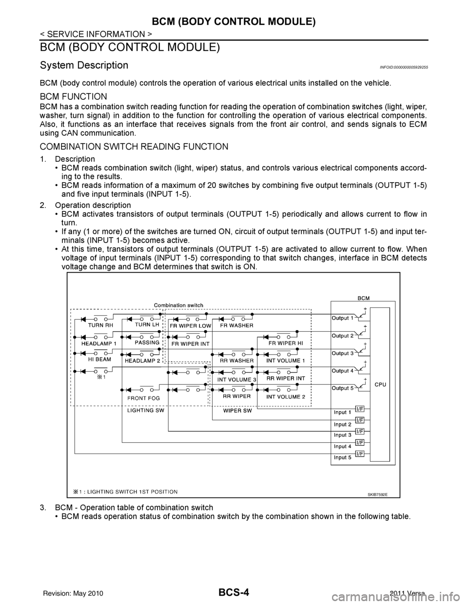
1. Description • BCM reads combination switch (light, wiper) status, and controls various electrical components accord-
ing to the results.
• BCM reads information of a maximum of 20 switches by combining five output terminals (OUTPUT 1-5)
and five input terminals (INPUT 1-5).
2. Operation description • BCM activates transistors of output terminals (OUTPU T 1-5) periodically and allows current to flow in
turn.
• If any (1 or more) of the switches are turned ON, circuit of output terminals (OUTPUT 1-5) and input ter- minals (INPUT 1-5) becomes active.
• At this time, transistors of output terminals (OUTPUT 1-5) are activated to allow current to flow. When
voltage of input terminals (INPUT 1-5) corresponding to that switch changes, interface in BCM detects
voltage change and BCM determines that switch is ON.
3. BCM - Operation table of combination switch • BCM reads operation status of combination switch by the combination shown in the following table.
SKIB7592E
Revision: May 2010 2011 Versa