2011 NISSAN TIIDA fuel system
[x] Cancel search: fuel systemPage 1250 of 3787
COMBINATION METERSDI-11
< SERVICE INFORMATION >
C
DE
F
G H
I
J
L
M A
B
DI
N
O P
Self-Diagnosis Mode of Combination MeterINFOID:0000000005929166
SELF-DIAGNOSIS MODE FUNCTION
• Self-diagnosis can check for continuity between meter control circuit and each meter (speedometer, tachom- eter and fuel gauge).
• Self-diagnosis can check for odo/trip meter and A/T indi cator (with A/T) or CVT indicator (with CVT) seg-
ment, low-fuel level warning lamp, low water temperature indicator lamp, and high water temperature warn-
ing lamp.
OPERATION PROCEDURE
1. Turn the ignition switch ON, and switch the odo/trip meter to “trip A” or “trip B”. NOTE:
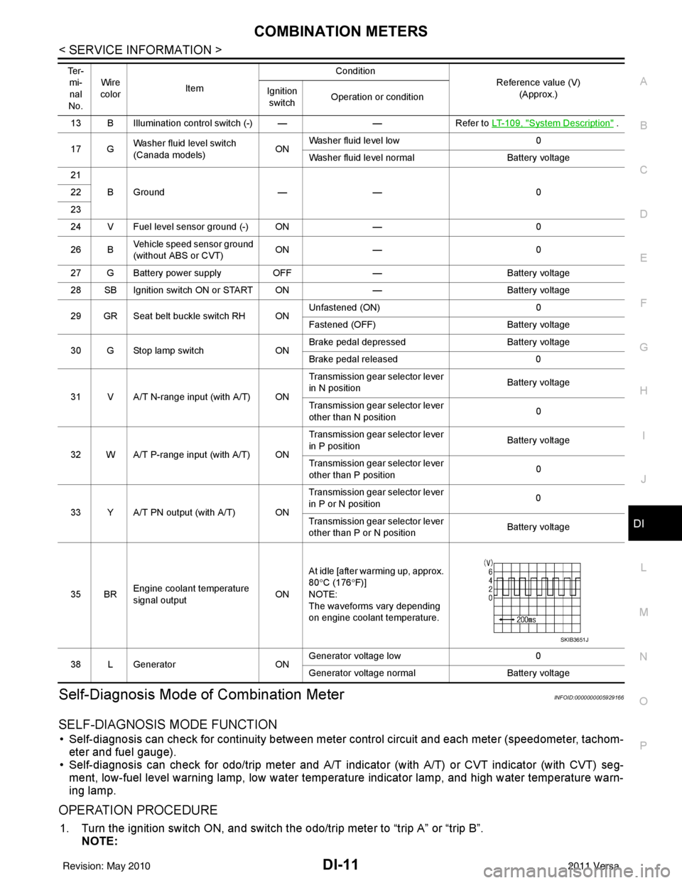
13 B Illumination control switch (-) — —Refer to LT- 1 0 9 , "System Description" .
17 G Washer fluid level switch
(Canada models)
ONWasher fluid level low
0
Washer fluid level normal Battery voltage
21 BGround —— 0
22
23
24 V Fuel level sensor ground (-) ON —0
26 B Vehicle speed sensor ground
(without ABS or CVT) ON
— 0
27 G Battery power supply OFF— Battery voltage
28 SB Ignition switch ON or START ON —Battery voltage
29 GR Seat belt buckle switch RH ON Unfastened (ON)
0
Fastened (OFF) Battery voltage
30 G Stop lamp switch ONBrake pedal depressed
Battery voltage
Brake pedal released 0
31 V A/T N-range input (with A/T) ON Transmission gear selector lever
in N position
Battery voltage
Transmission gear selector lever
other than N position 0
32 W A/T P-range input (with A/T) ON Transmission gear selector lever
in P position
Battery voltage
Transmission gear selector lever
other than P position 0
33 Y A/T PN output (with A/T) ON Transmission gear selector lever
in P or N position
0
Transmission gear selector lever
other than P or N position Battery voltage
35 BR Engine coolant temperature
signal output
ONAt idle [after warming up, approx.
80
°C (176 °F)]
NOTE:
The waveforms vary depending
on engine coolant temperature.
38 L Generator ONGenerator voltage low
0
Generator voltage no rmal Battery voltage
Te r -
mi-
nal
No. Wire
color Item Condition
Reference value (V)
(Approx.)
Ignition
switch Operation or condition
SKIB3651J
Revision: May 2010
2011 Versa
Page 1252 of 3787
COMBINATION METERSDI-13
< SERVICE INFORMATION >
C
DE
F
G H
I
J
L
M A
B
DI
N
O P
CONSULT-III Function (METER/M&A)INFOID:0000000005929167
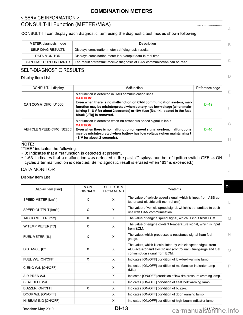
CONSULT-III can display each diagnostic item us ing the diagnostic test modes shown following.
SELF-DIAGNOSTIC RESULTS
Display Item List
NOTE:
“TIME” indicates the following.
• 0: Indicates that a malfunction is detected at present.
• 1-63: Indicates that a malfunction was detected in the past. (Displays number of ignition switch OFF → ON
cycles after malfunction is detected. Self-di agnostic result is erased when “63” is exceeded.)
DATA MONITOR
Display Item List
METER diagnosis mode Description
SELF-DIAG RESULTS Displays combination meter self-diagnosis results. DATA MONITOR Displays combination meter input/output data in real time.
CAN DIAG SUPPORT MNTR The result of transmit/receive diagnosis of CAN communication can be read.
CONSULT-III display MalfunctionReference page
CAN COMM CIRC [U1000] Malfunction is detected in CAN communication lines.
CAUTION:
Even when there is no malfuncti
on on CAN communication system, mal-
function may be misinterpreted when battery has low voltage (when main-
taining 7 - 8 V for about 2 seconds) or 10A fuse [No. 14, located in the fuse
block (J/B)] is removed. DI-19
VEHICLE SPEED CIRC [B2205]
Malfunction is detected when an erroneous speed signal is input.
CAUTION:
Even when there is no malfunction
on speed signal system, malfunctions
may be misinterpreted when battery has low voltage (when maintaining 7
- 8 V for about 2 seconds). DI-16
Display item [Unit]
MAIN
SIGNALS SELECTION
FROM MENU Contents
SPEED METER [km/h] XXThe value of vehicle speed signa
l, which is input from ABS ac-
tuator and electric unit (control unit).
SPEED OUTPUT [km/h] XXThe value of vehicle speed signal, which is transmitted to each
unit with CAN communication.
TACHO METER [rpm] XX The value of engine speed signal, which is input from ECM.
W TEMP METER [ °C] X XThe value of engine coolant temperature signal, which is input
from ECM.
FUEL METER [lit.] XXThe value, which processes a resistance signal from fuel
gauge.
DISTANCE [km] XXThe value, which is calculated by vehicle speed signal from
ABS actuator and electric unit (control unit), fuel gauge and fuel
consumption signal from ECM.
FUEL W/L [ON/OFF] XX Indicates [ON/OFF] condition of low-fuel warning lamp.
C-ENG W/L [ON/OFF] XIndicates [ON/OFF] condition of malfunction indicator lamp
(MIL).
AIR PRES W/L X Indicates [ON/OFF] condition of low tire pressure warning lamp.
SEAT BELT W/L X Indicates [ON/OFF] condition of seat belt warning lamp.
BUZZER [ON/OFF] XX Indicates [ON/OFF] condition of buzzer.
DOOR W/L [ON/OFF] X Indicates [ON/OFF] condition of door warning lamp.
HI-BEAM IND [ON/OFF] X Indicates [ON/OFF] condition of high beam indicator lamp.
Revision: May 2010 2011 Versa
Page 1258 of 3787
COMBINATION METERSDI-19
< SERVICE INFORMATION >
C
DE
F
G H
I
J
L
M A
B
DI
N
O P
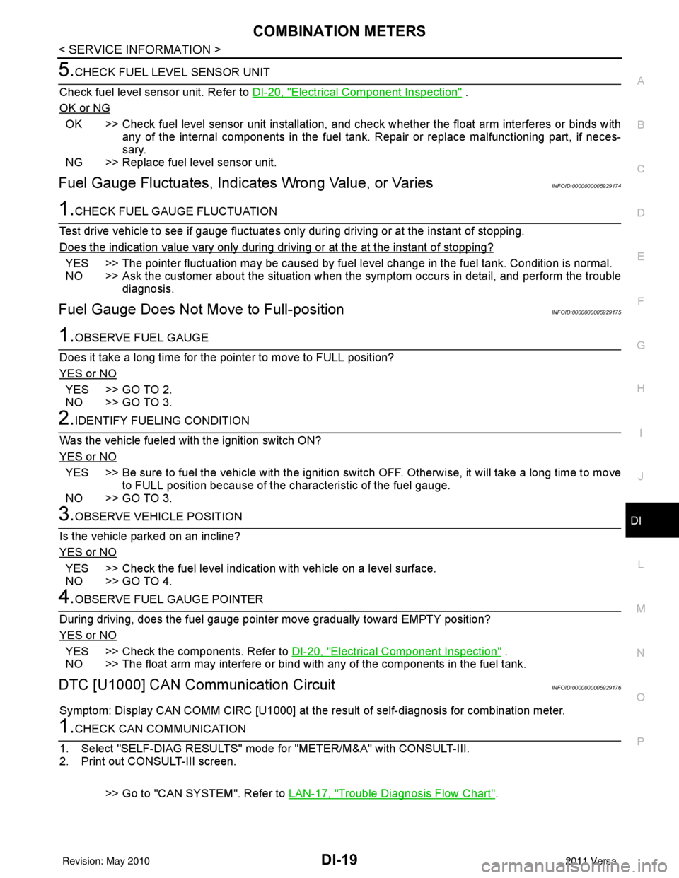
5.CHECK FUEL LEVEL SENSOR UNIT
Check fuel level sensor unit. Refer to DI-20, "
Electrical Component Inspection" .
OK or NG
OK >> Check fuel level sensor unit installation, and c heck whether the float arm interferes or binds with
any of the internal components in the fuel tank. Repair or replace malfunctioning part, if neces-
sary.
NG >> Replace fuel level sensor unit.
Fuel Gauge Fluctuates, Indica tes Wrong Value, or VariesINFOID:0000000005929174
1.CHECK FUEL GAUGE FLUCTUATION
Test drive vehicle to see if gauge fluctuates onl y during driving or at the instant of stopping.
Does the indication value vary only during dr iving or at the at the instant of stopping?
YES >> The pointer fluctuation may be caused by fuel level change in the fuel tank. Condition is normal.
NO >> Ask the customer about the situation when the symptom occurs in detail, and perform the trouble diagnosis.
Fuel Gauge Does Not Move to Full-positionINFOID:0000000005929175
1.OBSERVE FUEL GAUGE
Does it take a long time for the pointer to move to FULL position?
YES or NO
YES >> GO TO 2.
NO >> GO TO 3.
2.IDENTIFY FUELING CONDITION
Was the vehicle fueled with the ignition switch ON?
YES or NO
YES >> Be sure to fuel the vehicle with the ignition swit ch OFF. Otherwise, it will take a long time to move
to FULL position because of the c haracteristic of the fuel gauge.
NO >> GO TO 3.
3.OBSERVE VEHICLE POSITION
Is the vehicle parked on an incline?
YES or NO
YES >> Check the fuel level indicati on with vehicle on a level surface.
NO >> GO TO 4.
4.OBSERVE FUEL GAUGE POINTER
During driving, does the fuel gauge pointer move gradually toward EMPTY position?
YES or NO
YES >> Check the components. Refer to DI-20, "Electrical Component Inspection" .
NO >> The float arm may interfere or bind with any of the components in the fuel tank.
DTC [U1000] CAN Communication CircuitINFOID:0000000005929176
Symptom: Display CAN COMM CIRC [U1000] at the re sult of self-diagnosis for combination meter.
1.CHECK CAN COMMUNICATION
1. Select "SELF-DIAG RESULTS" mode for "METER/M&A" with CONSULT-III.
2. Print out CONSULT-III screen.
>> Go to "CAN SYSTEM". Refer to LAN-17, "
Trouble Diagnosis Flow Chart".
Revision: May 2010 2011 Versa
Page 1295 of 3787
EC-1
ENGINE
C
DE
F
G H
I
J
K L
M
SECTION EC
A
EC
N
O P
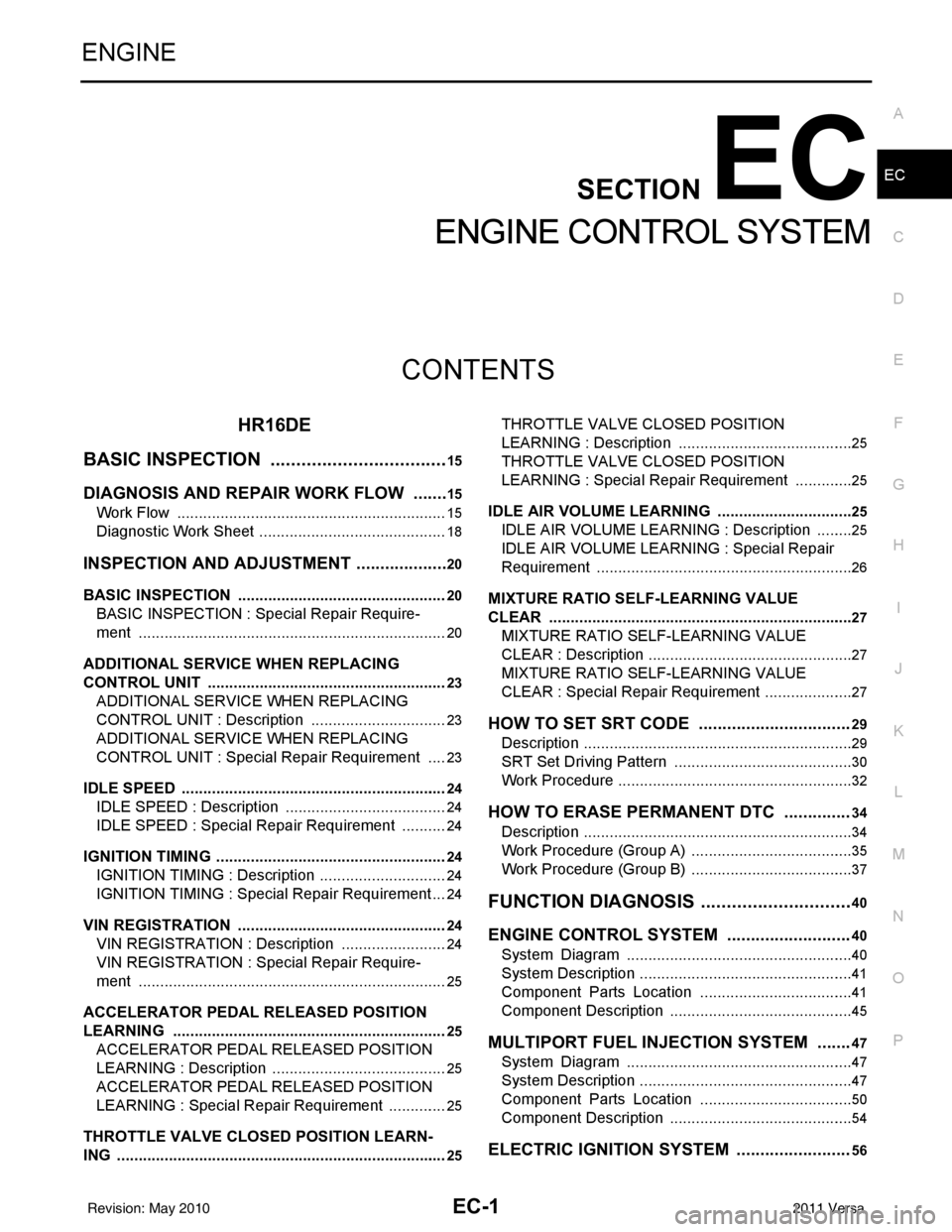
CONTENTS
ENGINE CONTROL SYSTEM
HR16DE
BASIC INSPECTION ....... ............................
15
DIAGNOSIS AND REPAIR WORK FLOW .... ....15
Work Flow ........................................................... ....15
Diagnostic Work Sheet ............................................18
INSPECTION AND ADJUSTMENT ....................20
BASIC INSPECTION .................................................20
BASIC INSPECTION : Spec ial Repair Require-
ment .................................................................... ....
20
ADDITIONAL SERVICE WHEN REPLACING
CONTROL UNIT .................................................... ....
23
ADDITIONAL SERVICE WHEN REPLACING
CONTROL UNIT : Description ................................
23
ADDITIONAL SERVICE WHEN REPLACING
CONTROL UNIT : Special Repair Requirement .....
23
IDLE SPEED .......................................................... ....24
IDLE SPEED : Description ........................ ..............24
IDLE SPEED : Special R epair Requirement ...........24
IGNITION TIMING .................................................. ....24
IGNITION TIMING : Description ..............................24
IGNITION TIMING : Special Repair Requirement ....24
VIN REGISTRATION ............................................. ....24
VIN REGISTRATION : Description .........................24
VIN REGISTRATION : Special Repair Require-
ment ........................................................................
25
ACCELERATOR PEDAL RELEASED POSITION
LEARNING ............................................................ ....
25
ACCELERATOR PEDAL RELEASED POSITION
LEARNING : Description .........................................
25
ACCELERATOR PEDAL RELEASED POSITION
LEARNING : Special Repair Requirement ..............
25
THROTTLE VALVE CLOSED POSITION LEARN-
ING ......................................................................... ....
25
THROTTLE VALVE CLOSED POSITION
LEARNING : Description .........................................
25
THROTTLE VALVE CLOSED POSITION
LEARNING : Special Repair Requirement ..............
25
IDLE AIR VOLUME LEARNING ............................ ....25
IDLE AIR VOLUME LEARNING : Description .........25
IDLE AIR VOLUME LEARNI NG : Special Repair
Requirement ........................................................ ....
26
MIXTURE RATIO SELF-LEARNING VALUE
CLEAR ................................................................... ....
27
MIXTURE RATIO SELF-LEARNING VALUE
CLEAR : Description ................................................
27
MIXTURE RATIO SELF-LEARNING VALUE
CLEAR : Special Repair Requirement .....................
27
HOW TO SET SRT CODE ................................29
Description ...............................................................29
SRT Set Driving Pattern ..........................................30
Work Procedure .......................................................32
HOW TO ERASE PERMANENT DTC ..............34
Description ...............................................................34
Work Procedure (Group A) ......................................35
Work Procedure (Group B) ......................................37
FUNCTION DIAGNOSIS ..............................40
ENGINE CONTRO L SYSTEM ..........................40
System Diagram ................................................. ....40
System Description ..................................................41
Component Parts Location ....................................41
Component Description ...........................................45
MULTIPORT FUEL INJECTION SYSTEM .......47
System Diagram .....................................................47
System Description ..................................................47
Component Parts Location ....................................50
Component Description ...........................................54
ELECTRIC IGNITION SYSTEM ........................56
Revision: May 2010 2011 Versa
Page 1297 of 3787
EC-3
C
DE
F
G H
I
J
K L
M
EC A
N
O P
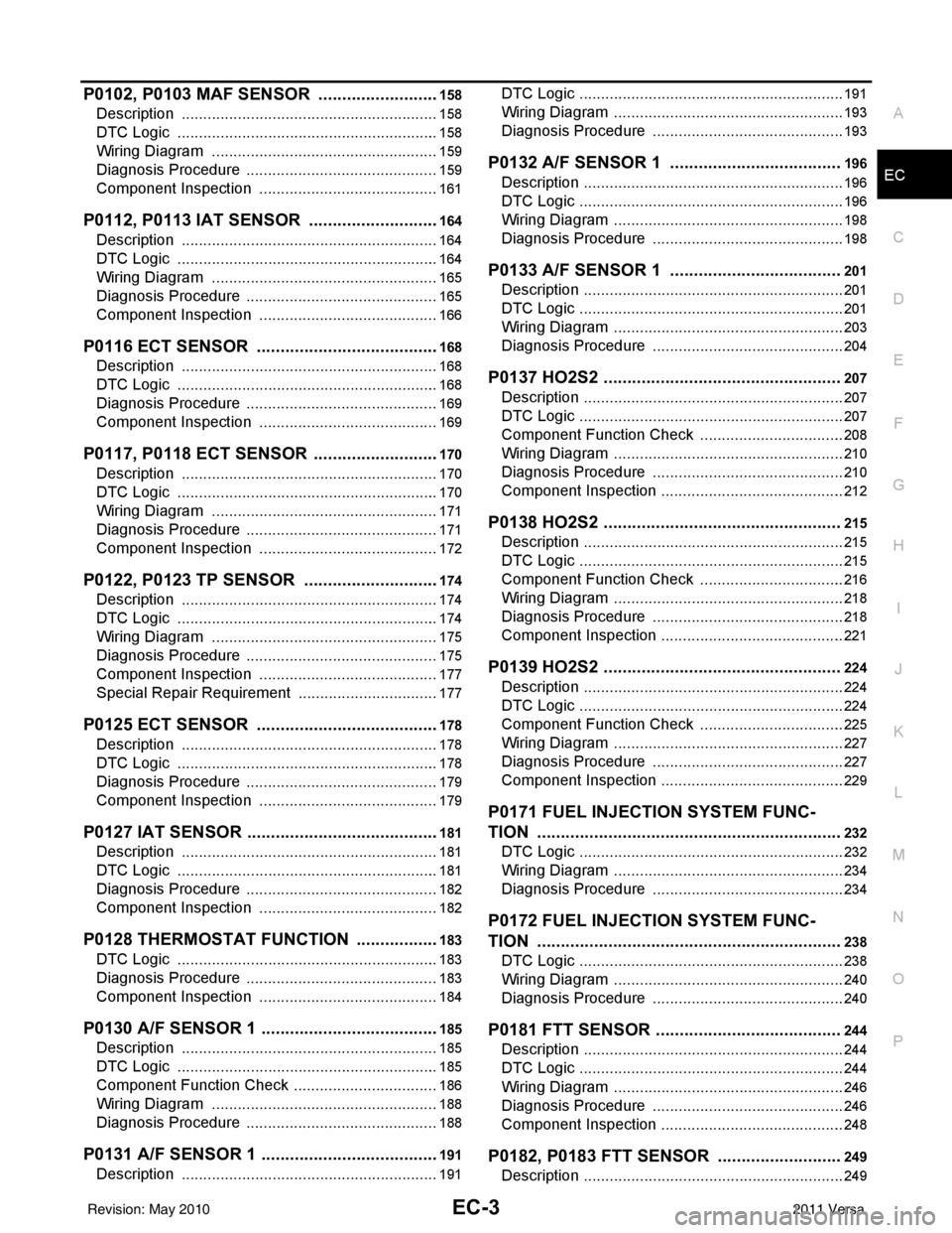
P0102, P0103 MAF SENSOR ........................ ..158
Description .......................................................... ..158
DTC Logic .............................................................158
Wiring Diagram .....................................................159
Diagnosis Procedure .............................................159
Component Inspection ..........................................161
P0112, P0113 IAT SENSOR ............................164
Description .......................................................... ..164
DTC Logic .............................................................164
Wiring Diagram .....................................................165
Diagnosis Procedure .............................................165
Component Inspection ..........................................166
P0116 ECT SENSOR .......................................168
Description .......................................................... ..168
DTC Logic .............................................................168
Diagnosis Procedure .............................................169
Component Inspection ..........................................169
P0117, P0118 ECT SENSOR ...........................170
Description .......................................................... ..170
DTC Logic .............................................................170
Wiring Diagram .....................................................171
Diagnosis Procedure .............................................171
Component Inspection ..........................................172
P0122, P0123 TP SENSOR .............................174
Description .......................................................... ..174
DTC Logic .............................................................174
Wiring Diagram .....................................................175
Diagnosis Procedure .............................................175
Component Inspection ..........................................177
Special Repair Requirement .................................177
P0125 ECT SENSOR ..................................... ..178
Description .......................................................... ..178
DTC Logic .............................................................178
Diagnosis Procedure .............................................179
Component Inspection ..........................................179
P0127 IAT SENSOR .........................................181
Description .......................................................... ..181
DTC Logic .............................................................181
Diagnosis Procedure .............................................182
Component Inspection ..........................................182
P0128 THERMOSTAT FUNCTION ..................183
DTC Logic ........................................................... ..183
Diagnosis Procedure .............................................183
Component Inspection ..........................................184
P0130 A/F SENSOR 1 ......................................185
Description ............................................................185
DTC Logic .............................................................185
Component Function Check ..................................186
Wiring Diagram .....................................................188
Diagnosis Procedure .............................................188
P0131 A/F SENSOR 1 ......................................191
Description ............................................................191
DTC Logic ............................................................ ..191
Wiring Diagram ......................................................193
Diagnosis Procedure .............................................193
P0132 A/F SENSOR 1 ....................................196
Description .............................................................196
DTC Logic ..............................................................196
Wiring Diagram ......................................................198
Diagnosis Procedure .............................................198
P0133 A/F SENSOR 1 ....................................201
Description .............................................................201
DTC Logic ..............................................................201
Wiring Diagram ......................................................203
Diagnosis Procedure .............................................204
P0137 HO2S2 ..................................................207
Description .............................................................207
DTC Logic ..............................................................207
Component Function Check ..................................208
Wiring Diagram ......................................................210
Diagnosis Procedure .............................................210
Component Inspection ...........................................212
P0138 HO2S2 ..................................................215
Description .............................................................215
DTC Logic ..............................................................215
Component Function Check ..................................216
Wiring Diagram ......................................................218
Diagnosis Procedure .............................................218
Component Inspection ...........................................221
P0139 HO2S2 ..................................................224
Description .............................................................224
DTC Logic ..............................................................224
Component Function Check ..................................225
Wiring Diagram ......................................................227
Diagnosis Procedure .............................................227
Component Inspection ...........................................229
P0171 FUEL INJECTION SYSTEM FUNC-
TION ................................................................
232
DTC Logic ..............................................................232
Wiring Diagram ......................................................234
Diagnosis Procedure .............................................234
P0172 FUEL INJECTION SYSTEM FUNC-
TION ................................................................
238
DTC Logic ..............................................................238
Wiring Diagram ......................................................240
Diagnosis Procedure .............................................240
P0181 FTT SENSOR .......................................244
Description .............................................................244
DTC Logic ..............................................................244
Wiring Diagram ......................................................246
Diagnosis Procedure .............................................246
Component Inspection ...........................................248
P0182, P0183 FTT SENSOR ..........................249
Description .............................................................249
Revision: May 2010 2011 Versa
Page 1298 of 3787

EC-4
DTC Logic ..............................................................249
Wiring Diagram ......................................................250
Diagnosis Procedure .............................................250
Component Inspection ...........................................252
P0222, P0223 TP SENSOR .............................253
Description ........................................................... ..253
DTC Logic ..............................................................253
Wiring Diagram ......................................................254
Diagnosis Procedure .............................................254
Component Inspection ...........................................256
Special Repair Requirement ..................................256
P0300, P0301, P0302, P0303, P0304 MIS-
FIRE ................................................................ .
257
DTC Logic ............................................................ ..257
Diagnosis Procedure .............................................258
P0327, P0328 KS .............................................263
Description ........................................................... ..263
DTC Logic ..............................................................263
Wiring Diagram ......................................................264
Diagnosis Procedure .............................................264
Component Inspection ...........................................265
P0335 CKP SENSOR (POS) ...........................267
Description ........................................................... ..267
DTC Logic ..............................................................267
Wiring Diagram ......................................................268
Diagnosis Procedure .............................................269
Component Inspection ...........................................271
P0340 CMP SENSOR (PHASE) ......................272
Description ........................................................... ..272
DTC Logic ..............................................................272
Wiring Diagram ......................................................274
Diagnosis Procedure .............................................274
Component Inspection ...........................................276
P0420 THREE WAY CATALYST FUNCTION .277
DTC Logic ..............................................................277
Component Function Check ..................................278
Diagnosis Procedure .............................................279
P0441 EVAP CONTROL SYSTEM ..................282
DTC Logic ............................................................ ..282
Component Function Check ..................................283
Diagnosis Procedure .............................................284
Component Inspection (Drain filter) .......................287
P0442 EVAP CONTROL SYSTEM ..................288
DTC Logic ............................................................ ..288
Diagnosis Procedure .............................................289
Component Inspection (Fuel filler cap) ..................293
Component Inspection (Drain filter) .......................293
P0443 EVAP CANISTER PURGE VOLUME
CONTROL SOLENOID VALVE .......................
295
Description ........................................................... ..295
DTC Logic ..............................................................295
Wiring Diagram ......................................................297
Diagnosis Procedure ............................................ .297
Component Inspection ..........................................300
P0444, P0445 EVAP CANISTER PURGE
VOLUME CONTROL SOLENOID VALVE .......
301
Description ........................................................... .301
DTC Logic .............................................................301
Wiring Diagram .....................................................302
Diagnosis Procedure .............................................302
Component Inspection ..........................................304
P0447 EVAP CANISTER VENT CONTROL
VALVE ..............................................................
305
Description ........................................................... .305
DTC Logic .............................................................305
Wiring Diagram .....................................................306
Diagnosis Procedure .............................................306
Component Inspection ..........................................308
P0448 EVAP CANISTER VENT CONTROL
VALVE ..............................................................
310
Description ........................................................... .310
DTC Logic .............................................................310
Wiring Diagram .....................................................312
Diagnosis Procedure .............................................312
Component Inspection ..........................................314
P0451 EVAP CONTROL SYSTEM PRES-
SURE SENSOR ................................................
316
Description ........................................................... .316
DTC Logic .............................................................316
Diagnosis Procedure .............................................316
Component Inspection ..........................................318
P0452 EVAP CONTROL SYSTEM PRES-
SURE SENSOR ................................................
319
Description ........................................................... .319
DTC Logic .............................................................319
Wiring Diagram .....................................................321
Diagnosis Procedure .............................................321
Component Inspection ..........................................324
P0453 EVAP CONTROL SYSTEM PRES-
SURE SENSOR ................................................
326
Description ........................................................... .326
DTC Logic .............................................................326
Wiring Diagram .....................................................328
Diagnosis Procedure .............................................328
Component Inspection ..........................................332
P0455 EVAP CONTROL SYSTEM ..................333
DTC Logic .............................................................333
Diagnosis Procedure .............................................334
Component Inspection (Fuel filler cap) .................337
Component Inspection (Drain filter) ......................338
P0456 EVAP CONTROL SYSTEM ..................339
DTC Logic .............................................................339
Component Function Check .................................341
Diagnosis Procedure .............................................341
Revision: May 2010 2011 Versa
Page 1299 of 3787
EC-5
C
DE
F
G H
I
J
K L
M
EC A
N
O P
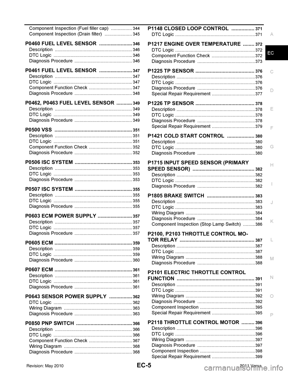
Component Inspection (Fuel filler cap) ...............
..
344
Component Inspection (Drain filter) ......................345
P0460 FUEL LEVEL SENSOR ...................... ..346
Description .......................................................... ..346
DTC Logic .............................................................346
Diagnosis Procedure .............................................346
P0461 FUEL LEVEL SENSOR ........................347
Description .......................................................... ..347
DTC Logic .............................................................347
Component Function Check ..................................347
Diagnosis Procedure .............................................348
P0462, P0463 FUEL LEVEL SENSOR ............349
Description .......................................................... ..349
DTC Logic .............................................................349
Diagnosis Procedure .............................................349
P0500 VSS .......................................................351
Description .......................................................... ..351
DTC Logic .............................................................351
Component Function Check ..................................352
Diagnosis Procedure .............................................352
P0506 ISC SYSTEM .........................................353
Description .......................................................... ..353
DTC Logic .............................................................353
Diagnosis Procedure .............................................353
P0507 ISC SYSTEM .........................................355
Description .......................................................... ..355
DTC Logic .............................................................355
Diagnosis Procedure .............................................355
P0603 ECM POWER SUPPLY .........................357
Description .......................................................... ..357
DTC Logic .............................................................357
Diagnosis Procedure .............................................357
P0605 ECM .......................................................359
Description ............................................................359
DTC Logic .............................................................359
Diagnosis Procedure .............................................360
P0607 ECM .......................................................361
Description ............................................................361
DTC Logic .............................................................361
Diagnosis Procedure .............................................361
P0643 SENSOR POWER SUPPLY .................362
DTC Logic ........................................................... ..362
Wiring Diagram .....................................................363
Diagnosis Procedure .............................................363
P0850 PNP SWITCH ........................................366
Description ............................................................366
DTC Logic .............................................................366
Component Function Check ..................................367
Wiring Diagram .....................................................368
Diagnosis Procedure .............................................368
P1148 CLOSED LOOP CONTROL ................371
DTC Logic ............................................................ ..371
P1217 ENGINE OVER TEMPERATURE ........372
DTC Logic ..............................................................372
Component Function Check ..................................372
Diagnosis Procedure .............................................373
P1225 TP SENSOR .........................................376
Description .............................................................376
DTC Logic ..............................................................376
Diagnosis Procedure .............................................376
Special Repair Requirement ..................................377
P1226 TP SENSOR .........................................378
Description .............................................................378
DTC Logic ..............................................................378
Diagnosis Procedure .............................................378
Special Repair Requirement ..................................379
P1421 COLD START CONTROL ...................380
Description .............................................................380
DTC Logic ..............................................................380
Diagnosis Procedure .............................................380
P1715 INPUT SPEED SENSOR (PRIMARY
SPEED SENSOR) ...........................................
382
Description ........................................................... ..382
DTC Logic ..............................................................382
Diagnosis Procedure .............................................382
P1805 BRAKE SWITCH .................................383
Description .............................................................383
DTC Logic ..............................................................383
Wiring Diagram ......................................................384
Diagnosis Procedure .............................................384
Component Inspection (Stop Lamp Switch) ..........386
P2100, P2103 THROTTLE CONTROL MO-
TOR RELAY ....................................................
387
Description .............................................................387
DTC Logic ..............................................................387
Wiring Diagram ......................................................388
Diagnosis Procedure .............................................388
P2101 ELECTRIC THROTTLE CONTROL
FUNCTION ......................................................
391
Description ........................................................... ..391
DTC Logic ..............................................................391
Wiring Diagram ......................................................392
Diagnosis Procedure .............................................392
Component Inspection ...........................................395
Special Repair Requirement ..................................395
P2118 THROTTLE CONTROL MOTOR .........396
Description .............................................................396
DTC Logic ..............................................................396
Wiring Diagram ......................................................397
Diagnosis Procedure .............................................397
Component Inspection ...........................................398
Special Repair Requirement ..................................399
Revision: May 2010 2011 Versa
Page 1300 of 3787

EC-6
P2119 ELECTRIC THROTTLE CONTROL
ACTUATOR .....................................................
400
Description ........................................................... ..400
DTC Logic ..............................................................400
Diagnosis Procedure .............................................400
Special Repair Requirement ..................................401
P2122, P2123 APP SENSOR ......................... .402
Description ........................................................... ..402
DTC Logic ..............................................................402
Wiring Diagram ......................................................403
Diagnosis Procedure .............................................403
Component Inspection ...........................................405
Special Repair Requirement ..................................405
P2127, P2128 APP SENSOR ......................... .406
Description ........................................................... ..406
DTC Logic ..............................................................406
Wiring Diagram ......................................................407
Diagnosis Procedure .............................................407
Component Inspection ...........................................409
Special Repair Requirement ..................................410
P2135 TP SENSOR ........................................ .411
Description ........................................................... ..411
DTC Logic ..............................................................411
Wiring Diagram ......................................................412
Diagnosis Procedure .............................................412
Component Inspection ...........................................414
Special Repair Requirement ..................................414
P2138 APP SENSOR ..................................... .415
Description ........................................................... ..415
DTC Logic ..............................................................415
Wiring Diagram ......................................................416
Diagnosis Procedure .............................................416
Component Inspection ...........................................419
Special Repair Requirement ..................................419
P2A00 A/F SENSOR 1 ................................... .420
Description ........................................................... ..420
DTC Logic ..............................................................420
Wiring Diagram ......................................................421
Diagnosis Procedure .............................................422
COOLING FAN ................................................425
Description ........................................................... ..425
Component Function Check ..................................425
Wiring Diagram ......................................................426
Diagnosis Procedure .............................................427
Component Inspection ...........................................429
ELECTRICAL LOAD SIGNAL .........................431
Description ........................................................... ..431
Component Function Check ..................................431
Diagnosis Procedure .............................................431
FUEL INJECTOR .............................................433
Description ........................................................... ..433
Component Function Check ..................................433
Wiring Diagram ......................................................434
Diagnosis Procedure ............................................ .434
Component Inspection ..........................................435
FUEL PUMP .....................................................437
Description ........................................................... .437
Component Function Check .................................437
Wiring Diagram .....................................................438
Diagnosis Procedure .............................................438
Component Inspection ..........................................440
IGNITION SIGNAL ............................................442
Description ........................................................... .442
Component Function Check .................................442
Wiring Diagram .....................................................443
Diagnosis Procedure .............................................444
Component Inspection (Ignition Coil with Power
Transistor) ............................................................ .
447
Component Inspection (Condenser-2) ..................448
MALFUNCTION INDICATOR LAMP ................449
Description ........................................................... .449
Component Function Check .................................449
Wiring Diagram .....................................................450
Diagnosis Procedure .............................................451
ON BOARD REFUELING VAPOR RECOV-
ERY (ORVR) .....................................................
453
Description ........................................................... .453
Component Function Check .................................453
Diagnosis Procedure .............................................453
Component Inspection (Refueling EVAP vapor cut
valve) ................................................................... .
456
Component Inspection (Drain filter) ......................458
POSITIVE CRANKCASE VENTILATION .........459
Description ........................................................... .459
Component Inspection ..........................................459
REFRIGERANT PRESSURE SENSOR ...........460
Description ........................................................... .460
Component Function Check .................................460
Wiring Diagram .....................................................461
Diagnosis Procedure .............................................461
ECU DIAGNOSIS ......................................464
ECM ................................................................ ..464
Reference Value .................................................. .464
Wiring Diagram — ENGINE CONTROL SYSTEM
— ..........................................................................
474
Fail Safe ...............................................................475
DTC Inspection Priority Chart .............................477
DTC Index ............................................................478
Test Value and Test Limit .....................................481
SYMPTOM DIAGNOSIS ...........................488
ENGINE CONTROL SYSTEM SYMPTOMS .. ..488
Symptom Table .................................................... .488
NORMAL OPERATING CONDITION ...............492
Revision: May 2010 2011 Versa