Page 1255 of 3787

DI-16
< SERVICE INFORMATION >
COMBINATION METERS
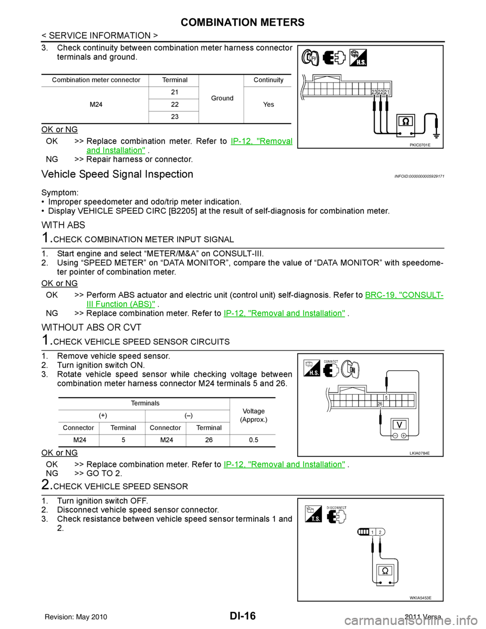
3. Check continuity between combination meter harness connectorterminals and ground.
OK or NG
OK >> Replace combination meter. Refer to IP-12, "Removal
and Installation" .
NG >> Repair harness or connector.
Vehicle Speed Signal InspectionINFOID:0000000005929171
Symptom:
• Improper speedometer and odo/trip meter indication.
• Display VEHICLE SPEED CIRC [B2205] at the result of self-diagnosis for combination meter.
WITH ABS
1.CHECK COMBINATION METER INPUT SIGNAL
1. Start engine and select “METER/M&A” on CONSULT-III.
2. Using “SPEED METER” on “DATA MONITOR”, comp are the value of “DATA MONITOR” with speedome-
ter pointer of combination meter.
OK or NG
OK >> Perform ABS actuator and electric uni t (control unit) self-diagnosis. Refer to BRC-19, "CONSULT-
III Function (ABS)" .
NG >> Replace combination meter. Refer to IP-12, "
Removal and Installation" .
WITHOUT ABS OR CVT
1.CHECK VEHICLE SPEED SENSOR CIRCUITS
1. Remove vehicle speed sensor.
2. Turn ignition switch ON.
3. Rotate vehicle speed sensor while checking voltage between combination meter harness connector M24 terminals 5 and 26.
OK or NG
OK >> Replace combination meter. Refer to IP-12, "Removal and Installation" .
NG >> GO TO 2.
2.CHECK VEHICLE SPEED SENSOR
1. Turn ignition switch OFF.
2. Disconnect vehicle speed sensor connector.
3. Check resistance between vehicle speed sensor terminals 1 and 2.
Combination meter connector Terminal
GroundContinuity
M24 21
Ye s
22
23
PKIC0701E
Te r m i n a l s
Voltag e
(Approx.)
(+)
(–)
Connector Terminal Connector Terminal M24 5M24 26 0.5
LKIA0784E
WKIA5453E
Revision: May 2010 2011 Versa
Page 1256 of 3787

COMBINATION METERSDI-17
< SERVICE INFORMATION >
C
DE
F
G H
I
J
L
M A
B
DI
N
O P
OK or NG
OK >> Check harness or connector between combination meter and vehicle speed sensor.
NG >> Replace vehicle speed sensor.
WITH CVT, WITHOUT ABS
1.CHECK COMBINATION METER INPUT SIGNAL
1. Start engine and select “M ETER/M&A” on CONSULT-III.
2. Using “SPEED METER” on “DATA MONITOR”, comp are the value of “DATA MONITOR” with speedome-
ter pointer of combination meter.
OK or NG
OK >> Perform TCM self-diagnosis. Refer to CVT-48, "CONSULT-III Function (TRANSMISSION)" .
NG >> Replace combination meter. Refer to IP-12, "
Removal and Installation" .
Engine Speed Signal InspectionINFOID:0000000005929172
Symptom: Improper tachometer indication.
1.CHECK COMBINATION METER INPUT SIGNAL
1. Start engine and select “M ETER/M&A” on CONSULT-III.
2. Using “TACHO METER” on “DATA MONITOR”, compare the value of “DATA MONITOR” with tachometer pointer of combination meter.
OK or NG
OK >> Perform ECM self-diagnosis. Refer to EC-612, "CONSULT-III Function (ENGINE)" (MR18DE) or
EC-106, "
CONSULT-III Function" (HR16DE).
NG >> Replace combination meter. Refer to IP-12, "
Removal and Installation" .
Fuel Level Sensor Signal InspectionINFOID:0000000005929173
Symptom:• Improper fuel gauge indication.
• Low-fuel warning lamp indication is irregular.
NOTE:
The following symptoms do not indicate a malfunction.
• Depending on vehicle position or driving circumstance, the fuel level in the tank shifts and the indication may fluctuate.
• If the vehicle is fueled with the ignition switch ON, the indication will update slowly.
• If the vehicle is tilted when the ignition switch is turned ON, fuel in the tank may flow to one direction result-
ing in a change of reading.
1.CHECK COMBINATION METER INPUT SIGNAL
1. Select “METER/M&A” on CONSULT-III.
2. Using “FUEL METER” on “DATA MONITOR”, compare the value of “DATA MONITOR” with fuel gauge pointer of combination meter.
Te r m i n a l s Resistance
value
(Approx.)
(+)
(–)
Component Terminal Component Terminal Ve h i c l e speed
sensor 1Vehicle
speed
sensor 22
50Ω
Fuel gauge pointer Reference value of data monitor [lit.]
Full Approx. 49
3/4 Approx. 34
1/2 Approx. 22
Revision: May 2010 2011 Versa
Page 1277 of 3787
DI-38
< SERVICE INFORMATION >
CVT INDICATOR
CVT INDICATOR
System DescriptionINFOID:0000000005929187
The TCM receives CVT indicator signals from the transmission range switch. The TCM then sends CVT posi-
tion indicator signals to the combination meter via CAN communication lines. The combination meter indicates
the received shift position.
SchematicINFOID:0000000005929188
ABNWA0597GB
Revision: May 2010 2011 Versa
Page 1278 of 3787
CVT INDICATORDI-39
< SERVICE INFORMATION >
C
DE
F
G H
I
J
L
M A
B
DI
N
O P
Wiring Diagram - CVTIND -INFOID:0000000005929189
LKWA0362E
Revision: May 2010 2011 Versa
Page 1279 of 3787
DI-40
< SERVICE INFORMATION >
CVT INDICATOR
ABNWA0846GB
Revision: May 20102011 Versa
Page 1280 of 3787
CVT INDICATORDI-41
< SERVICE INFORMATION >
C
DE
F
G H
I
J
L
M A
B
DI
N
O P
CVT Indicator Does Not IlluminateINFOID:0000000005929190
1.CHECK SEGMENT OF CVT INDICATOR
ABNWA0599GB
Revision: May 2010 2011 Versa
Page 1281 of 3787

DI-42
< SERVICE INFORMATION >
CVT INDICATOR
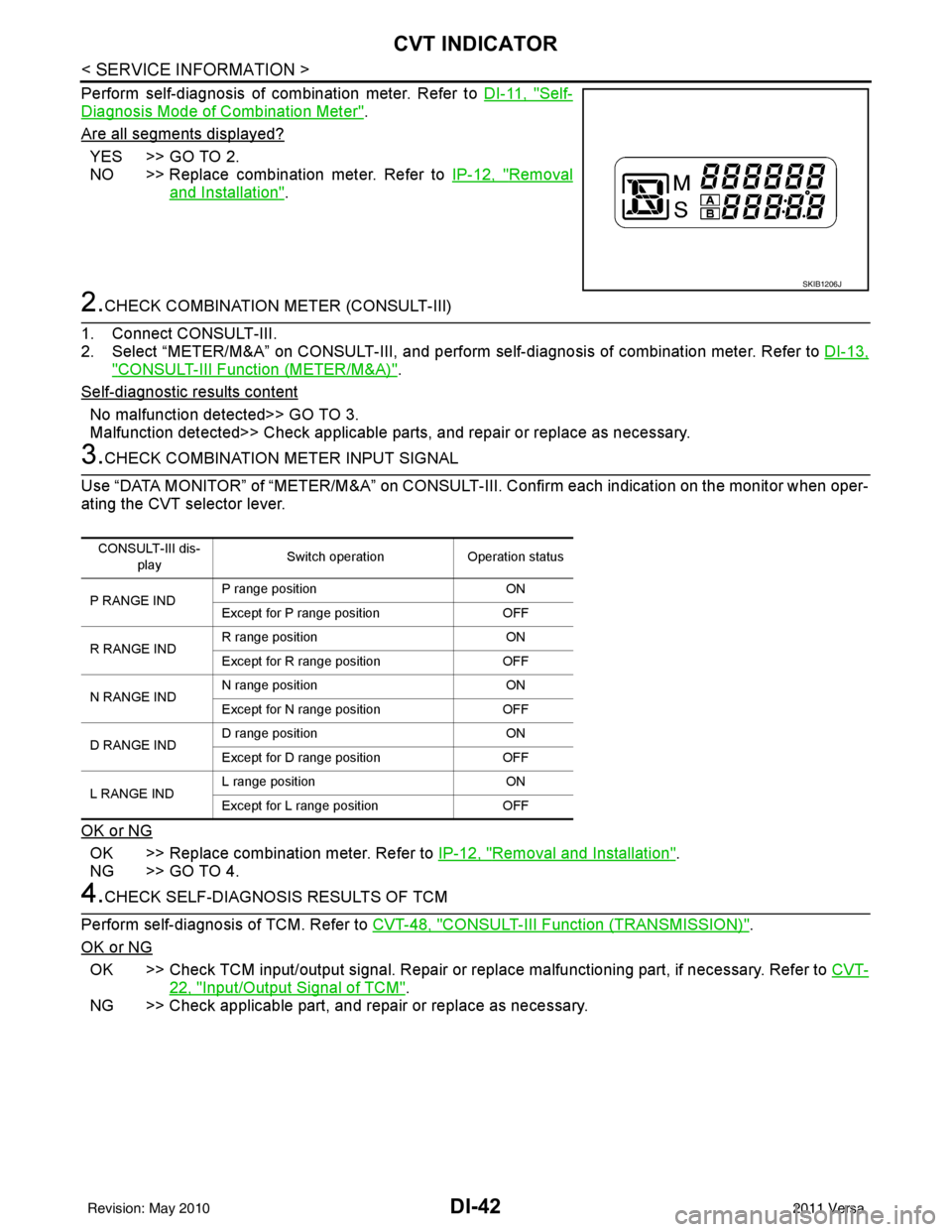
Perform self-diagnosis of combination meter. Refer to DI-11, "Self-
Diagnosis Mode of Combination Meter".
Are all segments displayed?
YES >> GO TO 2.
NO >> Replace combination meter. Refer to IP-12, "
Removal
and Installation".
2.CHECK COMBINATION METER (CONSULT-III)
1. Connect CONSULT-III.
2. Select “METER/M&A” on CONSULT- III, and perform self-diagnosis of combination meter. Refer to DI-13,
"CONSULT-III Function (METER/M&A)".
Self
-diagnostic results content
No malfunction detected>> GO TO 3.
Malfunction detected>> Check applicable parts, and repair or replace as necessary.
3.CHECK COMBINATION METER INPUT SIGNAL
Use “DATA MONITOR” of “METER/M&A” on CONSULT-III. Confirm each indication on the monitor when oper-
ating the CVT selector lever.
OK or NG
OK >> Replace combination meter. Refer to IP-12, "Removal and Installation".
NG >> GO TO 4.
4.CHECK SELF-DIAGNOSIS RESULTS OF TCM
Perform self-diagnosis of TCM. Refer to CVT-48, "
CONSULT-III Function (TRANSMISSION)".
OK or NG
OK >> Check TCM input/output signal. Repair or replace malfunctioning part, if necessary. Refer to CVT-
22, "Input/Output Signal of TCM".
NG >> Check applicable part, and repair or replace as necessary.
SKIB1206J
CONSULT-III dis-
play Switch operation
Operation status
P RANGE IND P range position
ON
Except for P range position OFF
R RANGE IND R range position
ON
Except for R range position OFF
N RANGE IND N range position
ON
Except for N range position OFF
D RANGE IND D range position
ON
Except for D range position OFF
L RANGE IND L range position
ON
Except for L range position OFF
Revision: May 2010 2011 Versa
Page 1284 of 3787
WARNING CHIMEDI-45
< SERVICE INFORMATION >
C
DE
F
G H
I
J
L
M A
B
DI
N
O P
• When the combination meter receives light warning signal, it sounds warning chime.
PARKING BRAKE WARNING CHIME
The parking brake warning chime sounds when the parking brake is applied and vehicle speed reaches
approximately 2 km/h (1 MPH).
• The combination meter receives a parking brake applied signal from the parking brake switch.
• When the combination meter receives a vehicle speed si gnal from the ABS actuator and electric unit (control
unit) (with ABS), vehicle speed sensor (without ABS or CVT) or the TCM (with CVT, without ABS), it sounds
the buzzer.
WKIA5465E
LKIA0906E
Revision: May 2010 2011 Versa